Week 09: OUTPUT DEVICES
A. BOARD DESIGN + FABRICATION
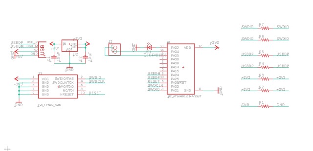


A1. Board Design
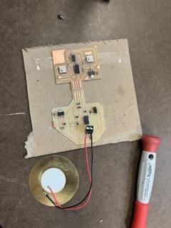
1.1 I used the same board that I used in week 8, so there is an in depth description on that page.
1.2 The important component for this week was the LED, because I wanted to connect my sensor's output to the LED, so that once the sensor reached a certain threshold the LED would turn on.
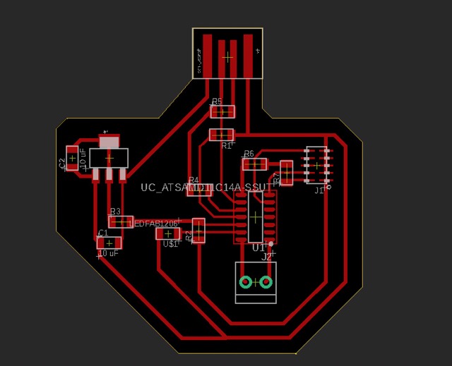
A2. Board Fabrication
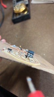
2.1 Again, I used the same board, so the more detailed description of the fabrication is in week 8.
2.2 However, one important thing to remember when soldering on your LED is that "green connects to ground." There is a little green line on one side of the LED which indicates the side of the LED component that should connect to your ground charge. If you solder it the wrong way around the LED won't turn on.
B. BOARD PROGRAMMING
B1. Programming my board
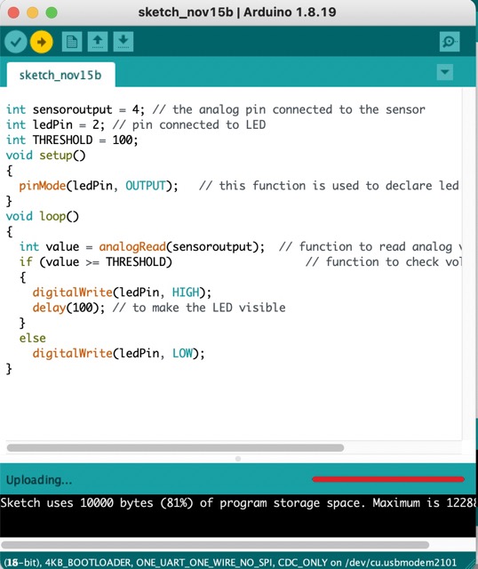
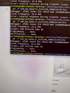
1.1 My board was already flashed from input devices week, so I just had to write a new code that would trigger the LED to turn on once the values from the piezo sensor reached above a certain threshold.
1.2 I first made sure to set the different variable to the correct pins that the components were connected to on my board. I checked my microcontroller datasheet to get the pin numbers.
1.3 Next I altered my previous code from week 8 by somewhat combining it with my week 6 LED + button code.
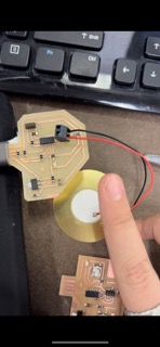
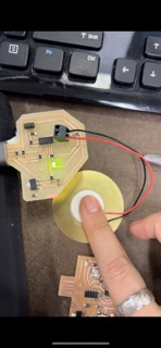
1.4 Photos of the working sensor and LED are below!