Week 02: ELECTRONICS PRODUCTION
A. MILLING
A1. Connecting your machine
1.1 To set up the machine I had to make sure the terminal, mods, and machine were all connected and working. I ran into many connection issues and it took me some time to figure out terminal and mods since all of this is very new to my non course 6 brain.
1.2 After lots of trouble shooting I found that in order to re-establish a connection you should shut off the milling machine, and ex out of any and all mods windows open on the computer, don't ex out of terminal!
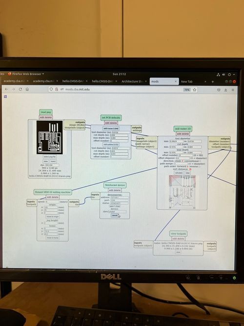
1.3 Then to establish the connection, turn on the milling machine and make sure the green light is steady and not blinking, then open terminal (if you accidentally closed out of it like I did you can find it again by clicking on the terminal icon on the desktop). Then open mods and navigate to the milling machine (programs > server programs > Roland Mill > SRM 20 > pcb png). Now you are ready to set up your machine!
A2. Setting up your machine
2.1 First you need to attach your mill bit (1/64 for traces, and 1/32 for interiors). To do this you carefully take a bit out of the drawer, do not drop or loose it! They are expensive! Then insert the mill bit into the machine, and use the tightening tool in the drawer under the machine to tighten the mill bit into place.
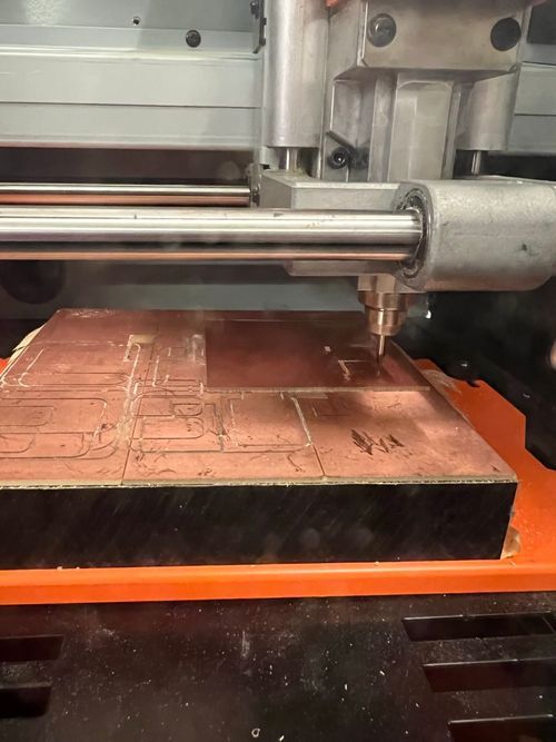
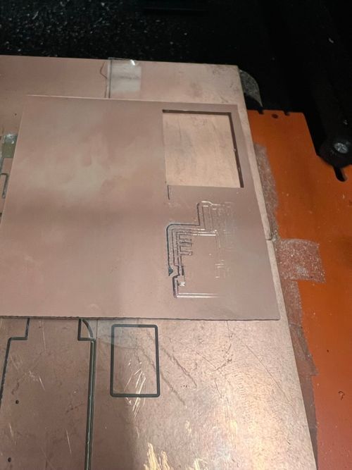
2.3 Then you need to attach your board by taping it to the existing copper plate. Try to find a place on the base board that isn't too worn out, because you need your copper piece to be completely flat in order for the mill to cut evenly. The first time I tried to mill only half of my board was cut, because my copper was uneven so the mill bit could only reach one half of it to cut. Don't make my mistake and make sure its taped down evenly!
2.4 Next you will set the x and y coordinates of the machine so that they are at the bottom left corner of where you want to cut. To do this you use the mods tab to change the x y origin points, and if your connection is working (go to part 1) the machine will move according to the coordinates you put in mods! This takes a little fiddling around and guesstimating to get your mill bit to the right space on your board.
2.5 Lastly you need to set your z coordinate to make sure the mill bit is far enough down on the copper. Set your z to 0 in mods and let the machine move to its z=0 position. Then, using the tightening tool for the mill bit, loosen the clamp on the bit and pull the mill bit down onto the copper. While you are still pulling the mill bit to the copper, tighten the mill bit clamp on the machine. This will ensure your bit will cut through the copper. This step is very important so that your mill will cut all the way through the copper, the first board I cut didn't cut through all the way on one side because I didn't pull my bit down into the copper as I was tightening it. Don't make my mistake and make sure you pull on the bit as you tighten! Now you are ready to cut.
A3. Cutting your file
3.1 First upload your jpg file of the traces of your board.
3.2 Then I selected 1/64 mill bit (which is standard for traces) and set my offset to 0 so that I wouldn't have to remove and excess copper from the board.
3.3 Once your machine is connected, mill bit installed, origin coordinates selected, and file uploaded you are ready to calculate the cut path! To do this just press calculate in mods and the machine will do its thing.
3.4 Now that the cut path is created you can send it to the machine and it will start milling!
3.5 Once the machine is done cutting your file, open the glass cover and use the vacuum to vacuum out all the excess copper bits. Leave your board on the plate because we still have to cut the interior!
3.6 Now you can upload your jpg file of the interior of your board.
3.7 You will have to change the mill bit to a 1/32 for cutting the interior. To do this follow the same steps as in part 2 but with the 1/32 bit instead of the 1/64.
3.8 Once your new bit is installed, set your x y z coordinates to the same ones from the first cut, and select 1/32 mill bit (which is standard for interior).
3.9 Now you can press calculate again and send it to the machine to cut!
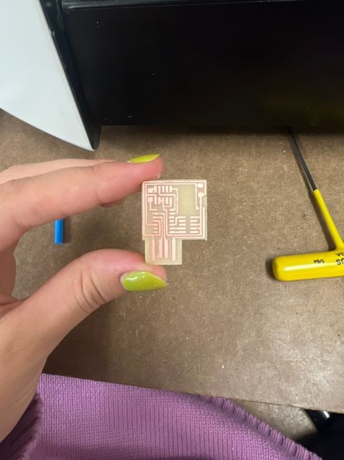
3.10 Once your board is cut, remove your entire copper piece from the board and make sure to quickly remove the tape so that it doesn't stick and make a mess for the next person.
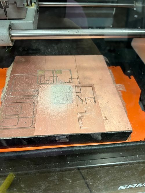
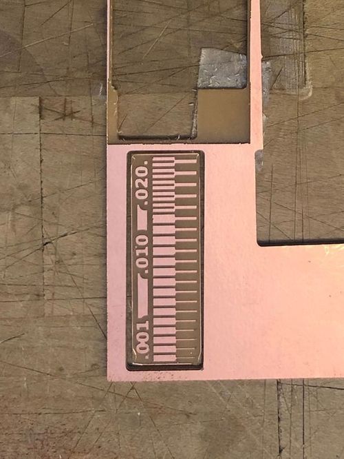
3.11 For the group assignment we printed the test board on the right to test the capabilities of the milling machine before we started.
B. SOLDERING
B1. Preparing your board
1.1 When I first tried soldering my board I had trouble with getting the solder to stop beading, if this happens do not turn up the temp!!
1.2 Instead first try sanding your board to get rid of excess copper. My board was a little jagged, because the mill bit was probably worn, so I sanded it down with sandpaper.
1.3 Then you'll want to clean your board with pumice soap (in the casting room for arch section). First apply the soap to the board dry and then rinse it off with water and pat down with paper towel.
1.4 Lastly you want to make sure your soldering iron is clean. Use the gold scrubby things next to the soldering station to clean off the tip of your iron.
B2. Finding the pieces
2.1 I was very clueless for this as I have never even seen a circuit board up close before so needed to get help from a fellow classmate. There are lots and lots of drawers with tiny little pieces.
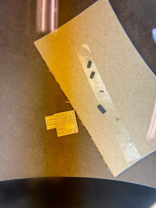
2.2 Once you find your pieces make sure to stick them onto a piece of tape attached to spare cardboard, this is so that you don’t loose all the teeny tiny pieces you are working with.
B3. Using the soldering iron
3.1 First you want to tin the tip of your soldering iron. I had a lot of trouble with this at first which is why I had to really scrub the tip of my iron clean in order for the solder to take to it. To do this just touch the tip of your iron to your solder and it should flow onto the tip easily.
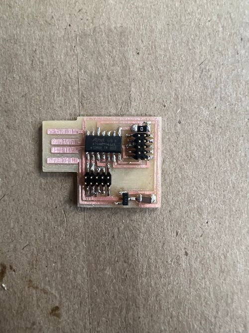
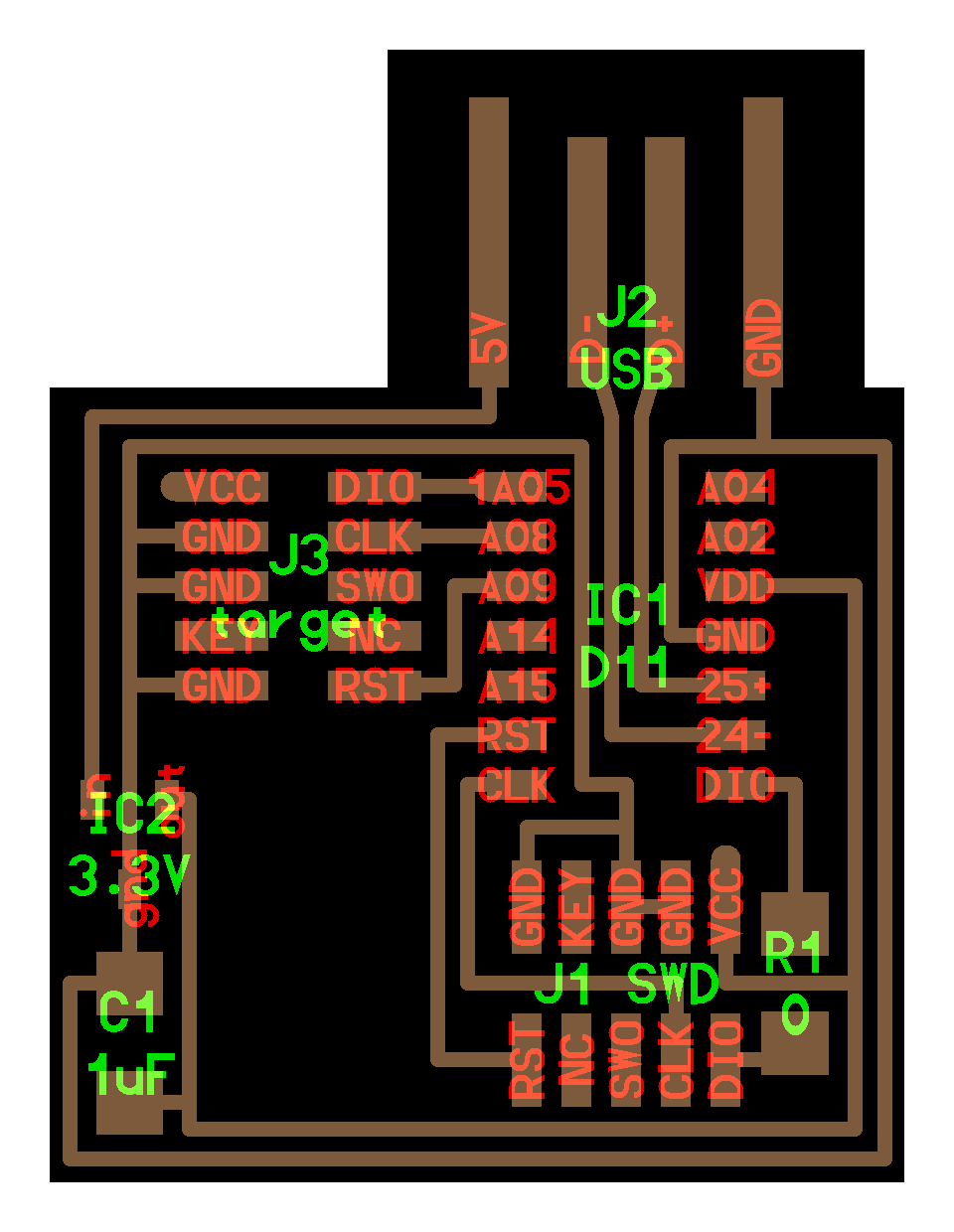
3.2 Next you want to place a small bit of solder onto the copper piece that you are planning to attach your electronic piece to. (Follow the images provided on the class website to know which piece goes where).
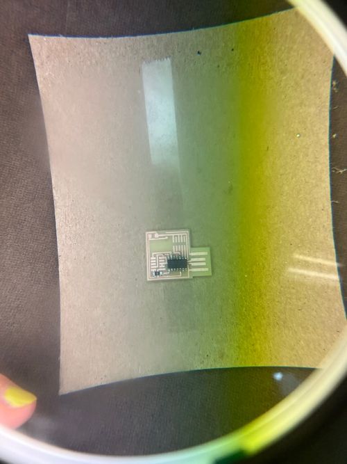
3.3 Then using your tweezers place the piece where you want to connect it, and touch the iron and solder to the electronic piece you want to connect. The solder should flow onto the electronic pieces foot and onto the copper below it. Then you go about attaching the rest of the feet by touching the iron and solder to them at the same time.
C. DEBUGGING
C1. Continuity Test
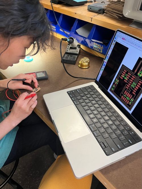
1.1 In order to debug the board you have to use the multimeter device to check for connections and bridging.
1.2 First check that all the ground pieces are connected. Touch one of the multimeter prongs to the foot you are testing and one to the ground piece. If the device beeps they are connected!
1.3 Second check that pieces that shouldn't be connected aren't. If you see any globby solder or a solder bridge, touch the multimeter prongs to the two parts you are testing and if it beeps that means they are connected and you have to remove the solder.
1.4 My board had a LOT of bugs and after a few hours of debugging I wasn't able to get it to work :( An entire electronic piece was bridged because there was solder underneath it, so I would have had to remake the whole board. I didn't want to waste parts on a board we wouldn't end up using so instead tried to document the debugging process for the board I made that didn't work. In order to create a working board I would go through the same steps, but this time with my improved soldering skills would make sure to use less solder when attaching my pieces so that they don't bridge.
C2. Removing unwanted solder
2.1 When I first started I used way too much solder and a lot of my pieces bridged together, to remove solder you need to take the copper wire and place it over the part you want to remove, and then touch your iron to the part on top of the copper wire.
2.2 I still haven't mastered this and had to use a combination or copper wire and scraping with an exacto knife to remove unwanted solder.