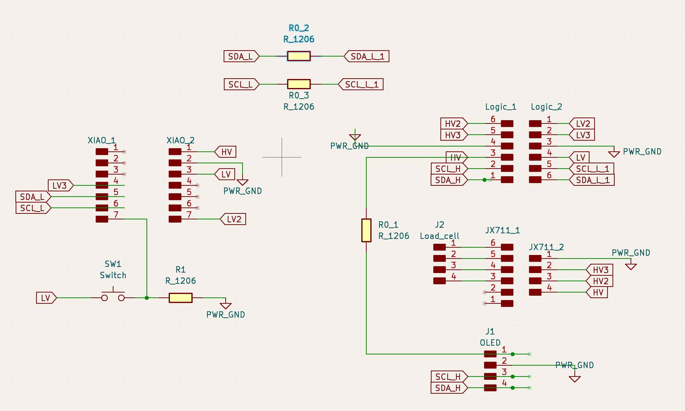
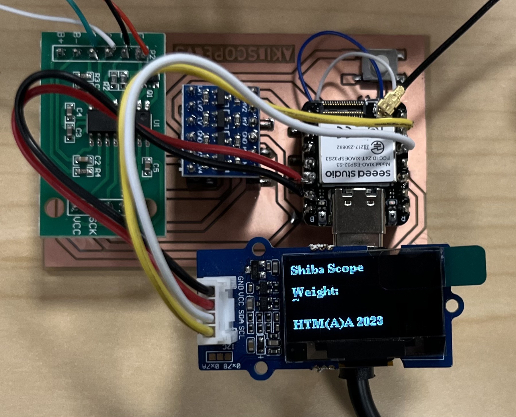
This week’s theme revolves around output devices, building upon the foundation of our previous project. In the previous week, I designed a PCB featuring the XIAO ESP32S3, a logic level converter, and a load cell module for weighing a dog bowl. For this week’s project, I took things a step further by incorporating a 0.96” OLED display as an output device, allowing for the visualization of data.
Show and Tell
To achieve the desired functionality, I wrote code to retrieve local time using WiFi and update the OLED display every second. This allowed for real-time display of important information, making the project both practical and user-friendly.
Hardware
- XIAO ESP32S3
- 0.96” OLED Display
- Bi-Directional Logic Level Converter Module (3.3V-5V)
- Load Cell Weight Sensor
Code (OLED display amd NTP time update)
  //---- OLED
  #include <U8g2lib.h>
  #ifdef U8X8_HAVE_HW_SPI
  #include <SPI.h>
  #endif
  #ifdef U8X8_HAVE_HW_I2C
  #include <Wire.h>
  #endif
  U8G2_SSD1306_128X64_NONAME_F_SW_I2C u8g2(U8G2_R0, /* clock=*/ SCL, /* data=*/ SDA, /* reset=*/ U8X8_PIN_NONE);

  //---- Wifi
  #include <WiFi.h>
  const char* ssid = "wifi_name";
  const char* password = "wifi_password";

  //---- Time
  #include "time.h"
  #include "sntp.h"
  const char* ntpServer1 = "pool.ntp.org";
  const char* ntpServer2 = "time.nist.gov";
  const long  gmtOffset_sec = -18000;    //For EST(winter) = UTC -5.00 : -5 * 60 * 60 : -18000
  const int   daylightOffset_sec = 3600; //Set it to 3600 if your country observes Daylight saving time; otherwise, set it to 0.
  const char* time_zone = "EST0EST,M3.2.0/2,M11.1.0/2";  // TimeZone rule for EST including daylight adjustment rules (optional)


  void setup() {
    Serial.begin(115200);                               // init serial port for debugging

    // OLED
    u8g2.begin();

    // Time, set notification call-back function
    sntp_set_time_sync_notification_cb( timeavailable );
    sntp_servermode_dhcp(1);    // (optional)
    configTime(gmtOffset_sec, daylightOffset_sec, ntpServer1, ntpServer2);

    // Send some msg
    Serial.printf("Connecting to %s ", ssid);
    u8g2.clearBuffer();                   // clear the internal memory
    u8g2.setFont(u8g2_font_ncenB08_tr);   // choose a suitable font
    u8g2.setCursor(0, 40);
    u8g2.print("Connecting to WiFi ");
    u8g2.sendBuffer();                    //  transfer internal memory to the display

    //connect to WiFi
    WiFi.begin(ssid, password);
    while (WiFi.status() != WL_CONNECTED) {
        delay(500);
        Serial.print(".");
    }
    Serial.println(" CONNECTED");
    u8g2.clearBuffer();                   // clear the internal memory
    u8g2.setFont(u8g2_font_ncenB08_tr);   // choose a suitable font
    u8g2.setCursor(0, 40);
    u8g2.print(" CONNECTED!");
    u8g2.sendBuffer();                    //  transfer internal memory to the display
    delay(500);
  }

  void loop() {
    u8g2.clearBuffer();                   // clear the internal memory
    u8g2.setFont(u8g2_font_ncenB08_tr);   // choose a suitable font
    u8g2.drawStr(0,10,"OLED Display Test");

    printLocalTime();

    delay(500);
  }

  void printLocalTime()
  {
    struct tm timeinfo;
    if(!getLocalTime(&timeinfo)){
      Serial.println("No time available (yet)");
      u8g2.setCursor(0, 30);
      u8g2.print("No time available (yet)");
      u8g2.sendBuffer();
      return;
    }
    Serial.println(&timeinfo, "%A, %B %d %Y %H:%M:%S");

    u8g2.drawStr(0,30,"Day: ");
    u8g2.setCursor(40, 30);
    u8g2.print(&timeinfo, "%A");

    u8g2.drawStr(0,40,"Date: ");
    u8g2.setCursor(40, 40);
    u8g2.print(&timeinfo, "%B %d");

    u8g2.drawStr(0,50,"Year: ");
    u8g2.setCursor(40, 50);
    u8g2.print(&timeinfo, "%Y");

    u8g2.drawStr(0,60,"Time: ");
    u8g2.setCursor(40, 60);
    u8g2.print(&timeinfo, "%H:%M:%S");

    u8g2.sendBuffer();                    // transfer internal memory to the display
  }

  // Callback function (get's called when time adjusts via NTP)
  void timeavailable(struct timeval *t)
  {
    Serial.println("Got time adjustment from NTP!");
    printLocalTime();
  }
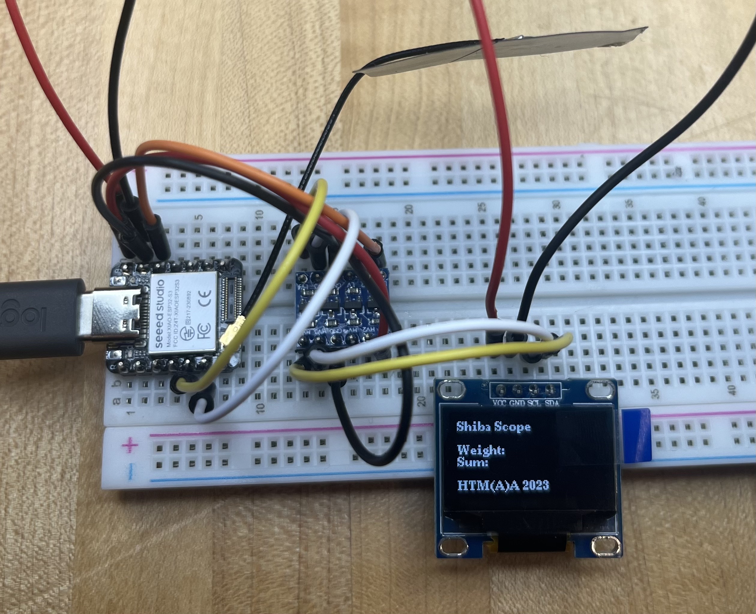
Challenge:
The main challenge I encountered during this project was the difference in logic levels between the XIAO ESP32S3 (3.3V) and the OLED module (5V). To overcome this hurdle, I employed a Logic Level Converter to adapt the signal pins (SDA and SCL) on a breadboard, effectively bridging the logic level gap. This solution proved effective, ensuring seamless communication between the XIAO and the OLED display.
Code (OLED test)
  //---- OLED
  #include <U8g2lib.h>
  #ifdef U8X8_HAVE_HW_SPI
  #include <SPI.h>
  #endif
  #ifdef U8X8_HAVE_HW_I2C
  #include <Wire.h>
  #endif
  U8G2_SSD1306_128X64_NONAME_F_SW_I2C u8g2(U8G2_R0, /* clock=*/ SCL, /* data=*/ SDA, /* reset=*/ U8X8_PIN_NONE);


  void setup() {
    Serial.begin(115200);                               // init serial port for debugging

    // OLED
    u8g2.begin();
  }

  void loop() {
    u8g2.clearBuffer();                   // clear the internal memory
    u8g2.setFont(u8g2_font_ncenB08_tr);   // choose a suitable font
    u8g2.drawStr(0,10,"Shiba Scope");    // write something to the internal memory

    u8g2.drawStr(0,30,"Weight: ");
    // u8g2.setCursor(60, 30);
    // u8g2.print(w1);

    u8g2.drawStr(0,40,"Sum: ");
    // u8g2.setCursor(60, 40);
    // u8g2.print(sum);

    u8g2.drawStr(0,60,"HTM(A)A 2023");
    // u8g2.setCursor(40, 60);
    // u8g2.print(WiFi.localIP());

    u8g2.sendBuffer();                    // transfer internal memory to the display

  }
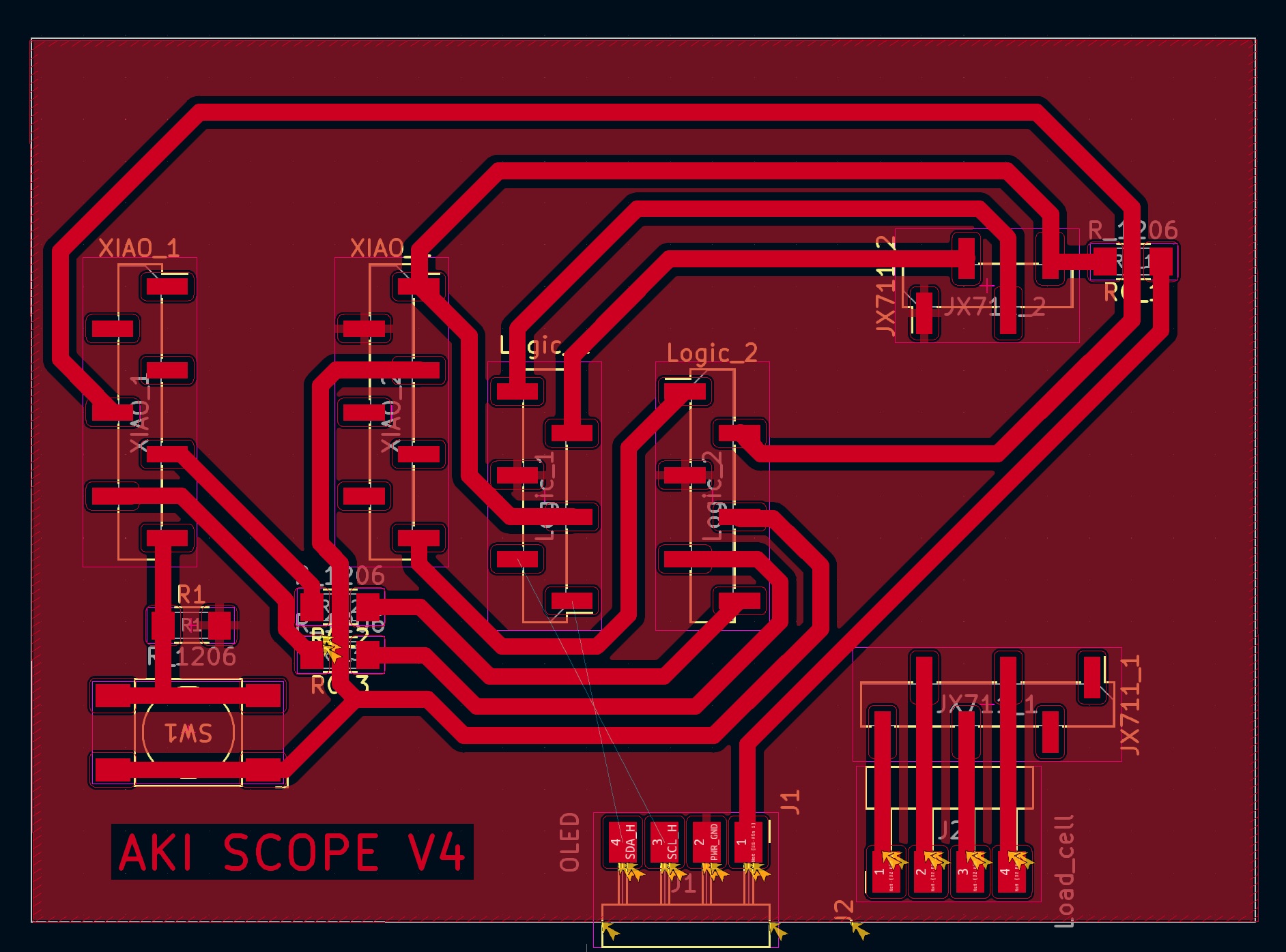
Updated PCB design
I made some updates to the PCB design to accommodate the integration of the OLED display and enhance the connectivity of the load cell.