This week, we learned how to turn electronics desgin into real pcb. First, we can export the board as a Gerber file or svg file for further fabrication.
Workflow
- gerber2img (gervber to image)
- I choose gerber2img cuz gerber file is standardized format for pcb design.
- Both Kicad and Fusion can easily export gerber file in default.
- mods project - G-Code Mill 2D PCB (Program -> Open a progeram -> G-Code -> Mill 2D PCB)
- For trace cutting
- Import “copper gerber file” png
- Choose “isolate traces (1/64)”
- Press “Calculate” under “mill raster 2D”
- Automatically download its .nc file - For edge cutting
- Import “edge file”
- Choose “mill outline (1/32)”
- Press “Calculate” under “mill raster 2D”
- Automatically download its .nc file
- Milling Machine (ugsplatform)
- How to run: https://winder.github.io/ugs_website/guide/platform/
- Ctrl + Alt + T
- In the terminal
cd Desktop/ugsplatform-linux/bin/ ./ugsplatform- import Gcode (Load .nc file from the last step)
- Check if the drill is the right one (1/64” for traces, 1/32” for edge cutting)
- Do “macro” -> “lift z axis”
- Do “macro” -> “position z position”
- Position the drill to the right potision and set X0 and Y0
- Press “send” and start milling.
- Post process
- Filing the edges with hand tool
- Alchahol wipe for removing oil and germ on top of the pcb
- Probing
- Using “beeping” mode on a digital multimeter to make sure the connection
- If there is mis-connection, use knife to cut off the trace
- Soldering
- Start to position the components (from the lowest height)
- Soldering it
- Probing again to make sure the connection
- Firmware upload and testing
- Upload the example code and test the basic blinking funtions
- Upload the main firmware for the boardm test the working funtions
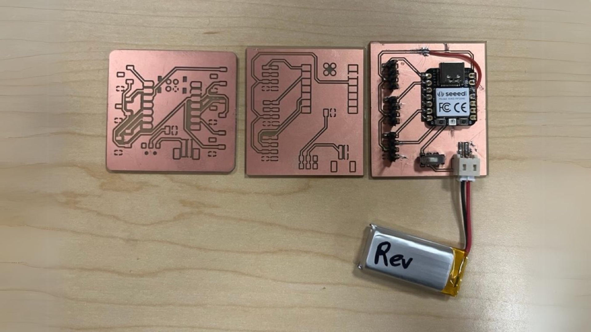
Fabrication Progress
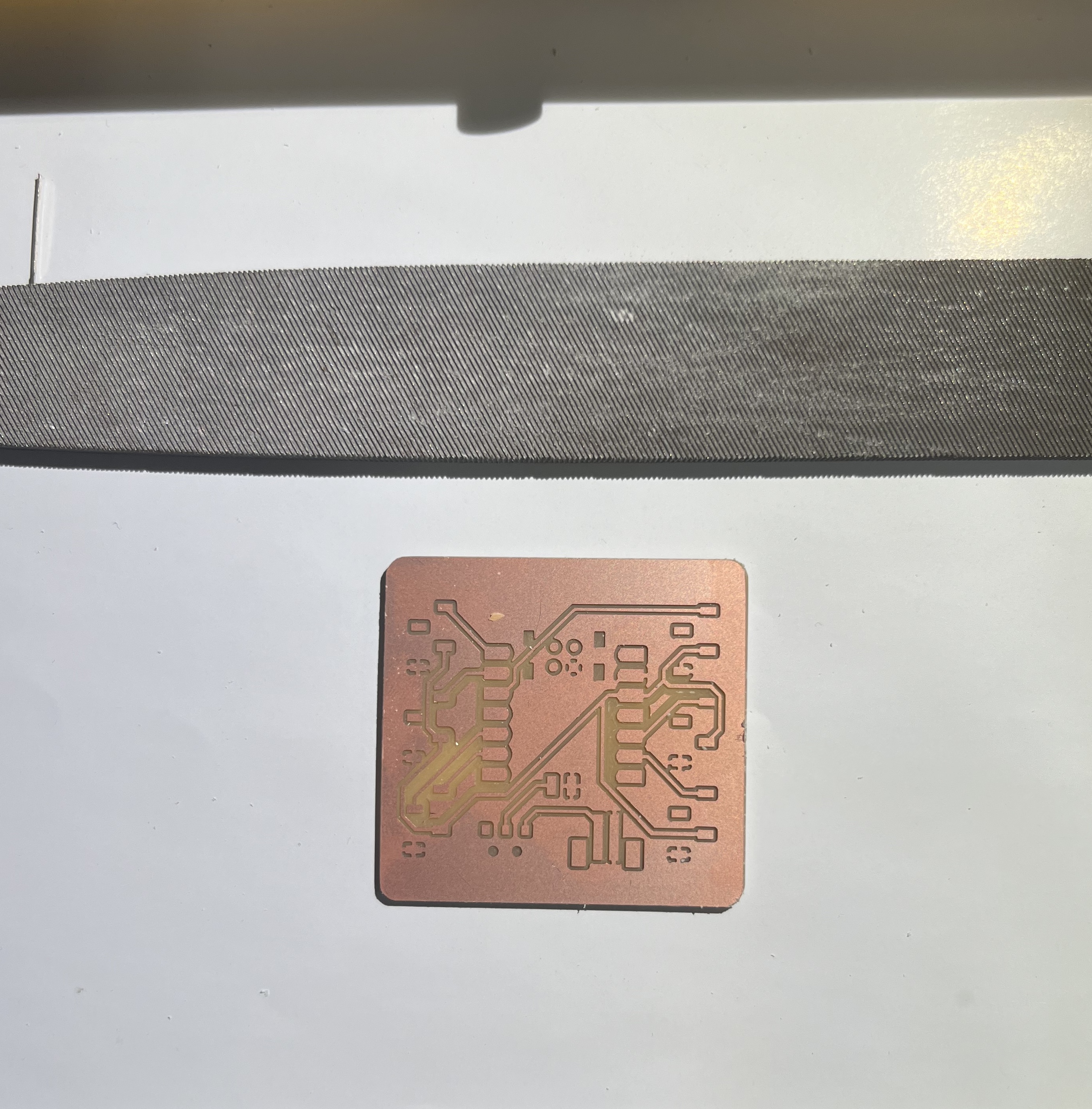
Here is the very first pcb I milled at the lab.
But I soon found some bugs (I reverted the li-pi power socked pins), I fixed it and re-mill the second and third version.
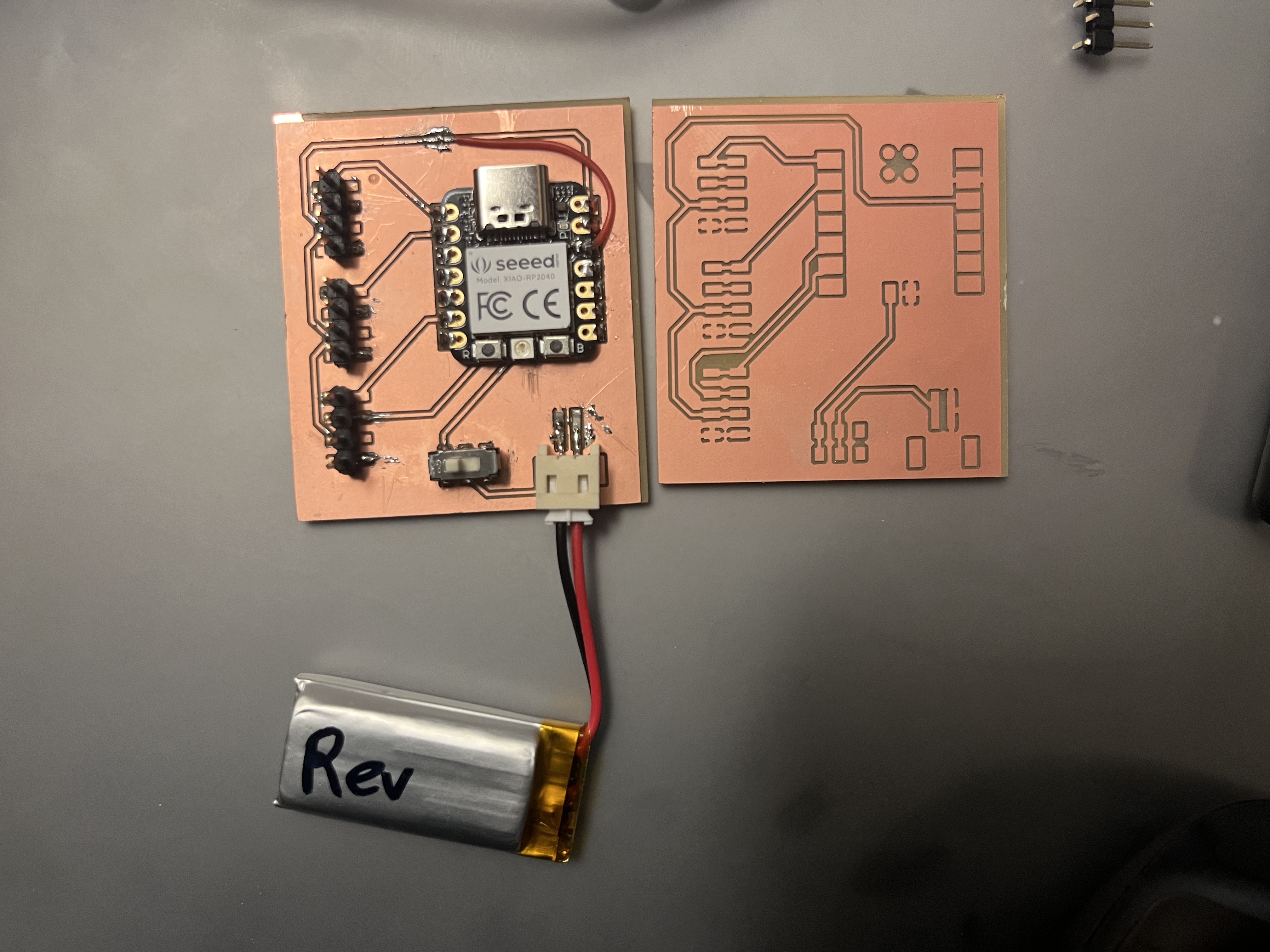
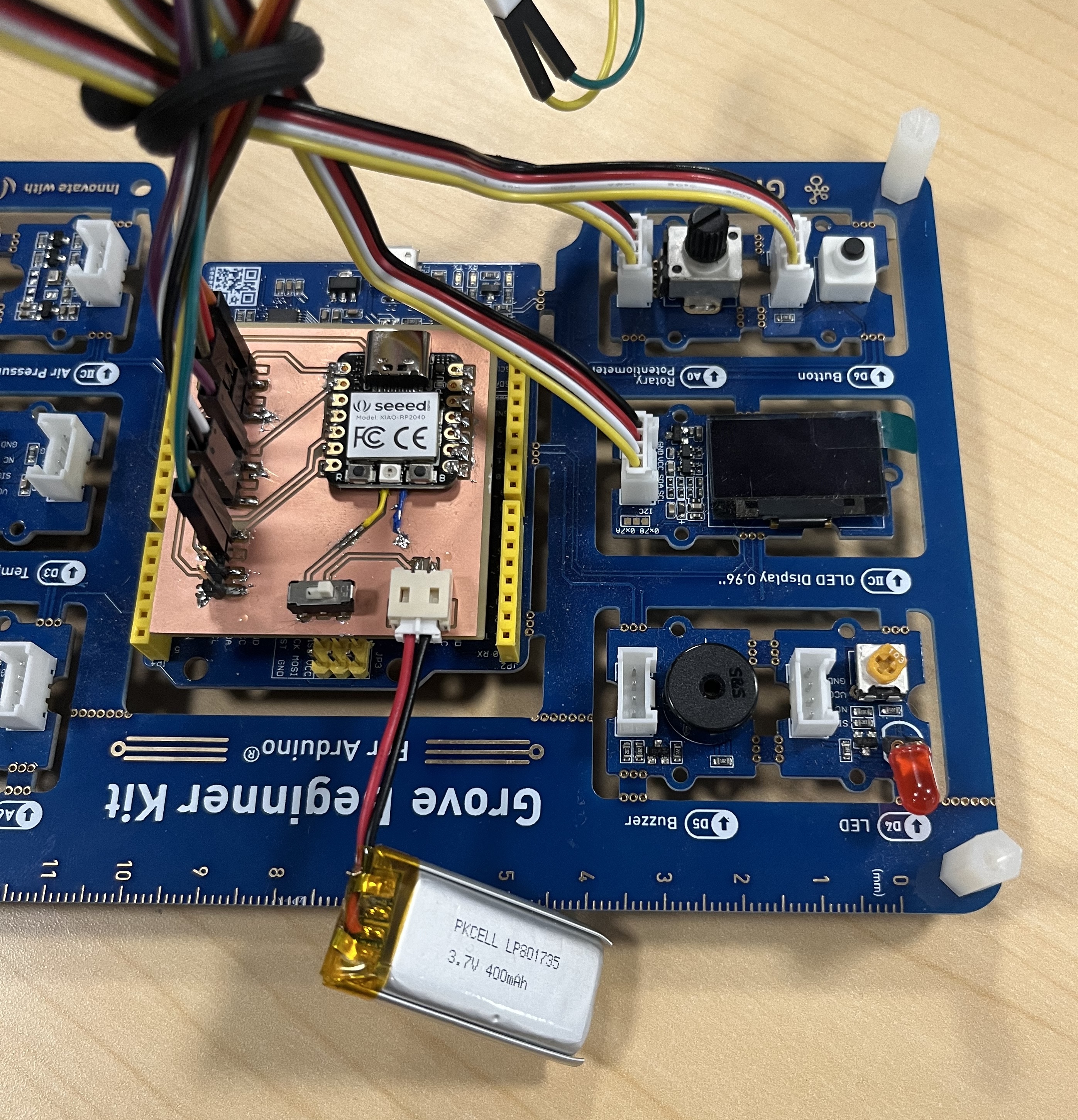
In the end, I got the funtional XIAO rp2040 dev board with a battery socket and 3 standard Grove connecter(I couldn’t find it in the lab, so I used male headers to replace it.)
Code
  #include <Adafruit_NeoPixel.h>
  #include <Arduino.h>
  #include <U8g2lib.h>

  #ifdef U8X8_HAVE_HW_SPI
  #include <SPI.h>
  #endif
  #ifdef U8X8_HAVE_HW_I2C
  #include <Wire.h>
  #endif
  U8G2_SSD1306_128X64_NONAME_F_SW_I2C u8g2(U8G2_R0, /* clock=*/ SCL, /* data=*/ SDA, /* reset=*/ U8X8_PIN_NONE);

  int Power = 11;
  int PIN  = 12;
  #define NUMPIXELS 1
  Adafruit_NeoPixel pixels(NUMPIXELS, PIN, NEO_GRB + NEO_KHZ800);

  const int sensorPin = A0;
  int sensorValue = 0;
  int neoValue = 0;
  int neoType = 0;
  char neoColor[] = "no light";

  const int buttonPin = D1;
  int buttonState = 0;
  int buttonPushCounter = 0;  // counter for the number of button presses
  int lastButtonState = 0;    // previous state of the button

  void setup() {
    Serial.begin(9600);

    pixels.begin();
    pinMode(Power,OUTPUT);
    digitalWrite(Power, HIGH);

    u8g2.begin();

    // declare the ledPin as an OUTPUT:
    pinMode(sensorPin, INPUT);
    // declare the buttonPin as an INPUT:
    pinMode(buttonPin, INPUT);

  }

  void loop() {

    // read the state of the pushbutton value:
    buttonState = digitalRead(buttonPin);
    button_edge_detection();

    // read the value from the sensor:
    sensorValue = analogRead(sensorPin);
    neoValue = map(sensorValue, 0, 1023, 30, 255);
    serialHandle();
    neoUpdater();
    oledUpdater();
    Serial.println(neoValue); //0-1023}
  }

  void serialHandle(){
    if (Serial.available() > 0) {
      int inByte = Serial.read();

        switch (inByte) {

          case 'r':
            strcpy(neoColor,"red");
            neoType = inByte;
            pixels.clear();
            pixels.setPixelColor(0, pixels.Color(neoValue, 15, 15));
            pixels.show();
            break;

          case 'g':
            strcpy(neoColor,"green");
            neoType = inByte;
            pixels.clear();
            pixels.setPixelColor(0, pixels.Color(15, neoValue, 15));
            pixels.show();
            break;

          case 'b':
            strcpy(neoColor,"blue");
            neoType = inByte;
            pixels.clear();
            pixels.setPixelColor(0, pixels.Color(15, 15, neoValue));
            pixels.show();
            break;

          case 'w':
            strcpy(neoColor,"white");
            neoType = inByte;
            pixels.clear();
            pixels.setPixelColor(0, pixels.Color(neoValue, neoValue, neoValue));
            pixels.show();
            break;

          case 'e':
            strcpy(neoColor,"no light");
            neoType = inByte;
            pixels.clear();
            pixels.show();
            break;

          default:
            pixels.show();
        }
    }
  }

  void neoUpdater(){
    switch (neoType) {

      case 'r':
        pixels.clear();
        pixels.setPixelColor(0, pixels.Color(neoValue, 15, 15));
        pixels.show();
        break;

      case 'g':
        pixels.clear();
        pixels.setPixelColor(0, pixels.Color(15, neoValue, 15));
        pixels.show();
        break;

      case 'b':
        pixels.clear();
        pixels.setPixelColor(0, pixels.Color(15, 15, neoValue));
        pixels.show();
        break;

      case 'w':
        pixels.clear();
        pixels.setPixelColor(0, pixels.Color(15, 15, 15));
        pixels.show();
        break;

      case 'e':
        pixels.clear();
        pixels.show();
        break;

      default:
        pixels.show();
    }
  }

  void oledUpdater(){
    u8g2.clearBuffer();                   // clear the internal memory
    u8g2.setFont(u8g2_font_ncenB08_tr);   // choose a suitable font
    u8g2.drawStr(0,10,"HTM(A)A 2023");    // write something to the internal memory

    u8g2.drawStr(0,30,"anaInput: ");
    u8g2.setCursor(60, 30);
    u8g2.print(sensorValue);

    // uint32_t color = pixels.getPixelColor(0);
    u8g2.drawStr(0,40,"neoValue: ");
    u8g2.setCursor(60, 40);
    u8g2.print(neoValue);

    //u8g2.drawStr(0,60,"test light ");
    u8g2.setCursor(0, 60);
    u8g2.print(neoColor);


    u8g2.sendBuffer();                    // transfer internal memory to the display


    Serial.println(neoValue);
  }

  void button_edge_detection(){

    // compare the buttonState to its previous state
    if (buttonState != lastButtonState) {
      // if the state has changed, increment the counter
      if (buttonState == HIGH) {
        // if the current state is HIGH then the button went from off to on:
        buttonPushCounter++;
        Serial.println("on");
        Serial.print("number of button pushes: ");
        Serial.println(buttonPushCounter);
      } else {
        // if the current state is LOW then the button went from on to off:
        Serial.println("off");
      }
      // Delay a little bit to avoid bouncing
      delay(50);
    }
    // save the current state as the last state, for next time through the loop
    lastButtonState = buttonState;


    // turns on the LED every four button pushes by checking the modulo of the
    // button push counter. the modulo function gives you the remainder of the
    // division of two numbers:
    if (buttonPushCounter % 5 == 0) {
    // check if the pushbutton is pressed. If it is, the buttonState is HIGH:
      Serial.println("no light");
      neoType = int('e');
      strcpy(neoColor,"no light");
    }
    else if(buttonPushCounter % 5 == 1){
      Serial.println("r");
      neoType = int('r');
      strcpy(neoColor,"red");
    }
    else if(buttonPushCounter % 5 == 2){
      Serial.println("g");
      neoType = int('g');
      strcpy(neoColor,"green");
    }
    else if(buttonPushCounter % 5 == 3){
      Serial.println("b");
      neoType = int('b');
      strcpy(neoColor,"blue");
    }
    else { //buttonPushCounter % 5 == 4
      Serial.println("w");
      neoType = int('w');
      strcpy(neoColor,"white");
    }
  }