This week, I delved into the exciting world of circuit design by incorporating input devices into my project. For this particular week, I opted to use load sensors as the input device and implemented a setup involving the HX711 module, a high-precision 24-Bit Analog-to-Digital Converter (ADC) commonly used in weigh scales. Additionally, I integrated a button into the circuit for recalibrating the weigh scale. In this post, I will walk you through the hardware components, libraries used, and the challenges I faced and overcame during this circuit design journey.
Hardware:
- XIAO ESP32S3 (originally XIAO RP2040, later switched to XIAO - ESP32S3 for upcoming WiFi connectivity)
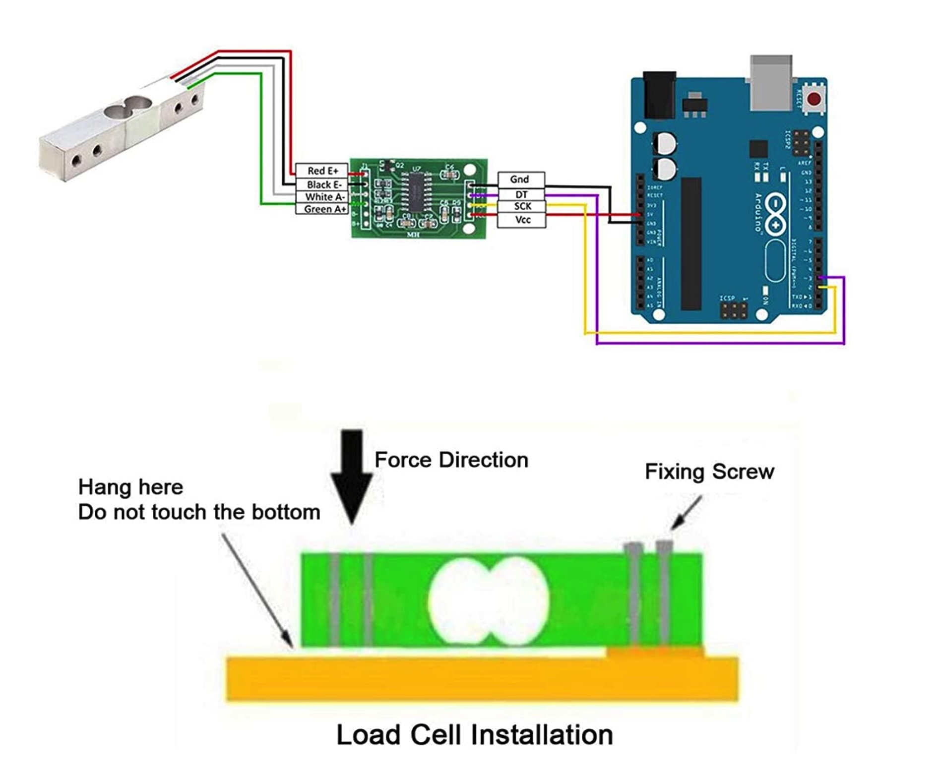
- Load Cell Weight Sensor
- AD HX711 Weighing Pressure Module
- Bi-Directional Logic Level Converter Module (3.3V-5V)
Library:
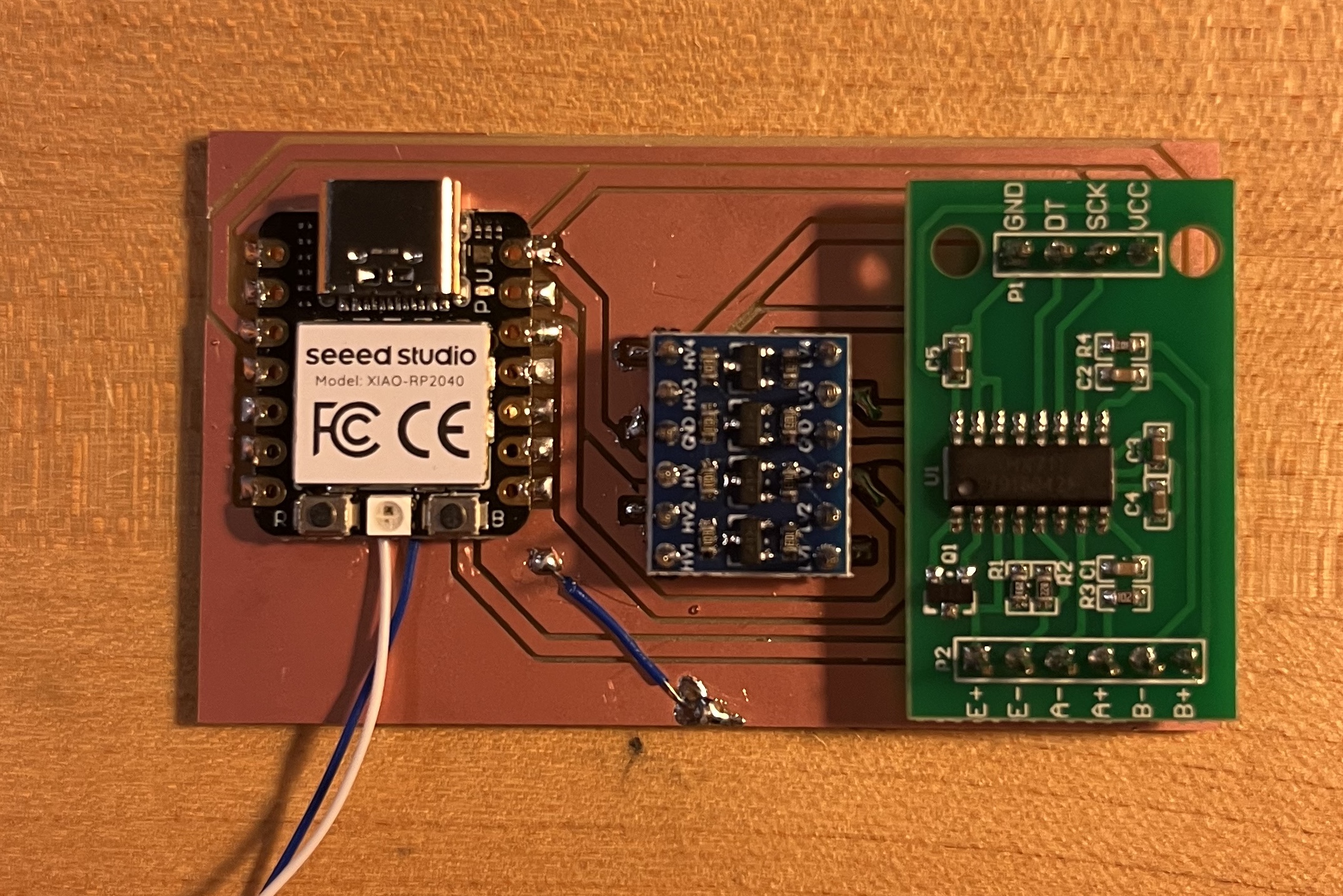
- HX711 Challenge 1 - Logic Level Conversion: One of the initial challenges I encountered was the difference in logic levels between the HX711 module (5V) and the XIAO ESP32S3 (3.3V). To bridge this gap, I employed a “Bi-Directional Logic Level Converter” to safely convert the 5V logic level to 3.3V, ensuring seamless compatibility between the components.
Step 1- Calibration:
Code:
  #include "HX711.h"

  HX711 myScale;

  uint8_t dataPin = 2;
  uint8_t clockPin = 1;

  uint32_t start, stop;
  volatile float f;


  void setup()
  {
    Serial.begin(115200);
    Serial.println(__FILE__);
    Serial.print("LIBRARY VERSION: ");
    Serial.println(HX711_LIB_VERSION);
    Serial.println();

    myScale.begin(dataPin, clockPin);
  }

  void loop()
  {
    calibrate();
  }


  void calibrate()
  {
    Serial.println("\n\nCALIBRATION\n===========");
    Serial.println("remove all weight from the loadcell");
    //  flush Serial input
    while (Serial.available()) Serial.read();

    Serial.println("and press enter\n");
    while (Serial.available() == 0);

    Serial.println("Determine zero weight offset");
    myScale.tare(20);  // average 20 measurements.
    uint32_t offset = myScale.get_offset();

    Serial.print("OFFSET: ");
    Serial.println(offset);
    Serial.println();


    Serial.println("place a weight on the loadcell");
    //  flush Serial input
    while (Serial.available()) Serial.read();

    Serial.println("enter the weight in (whole) grams and press enter");
    uint32_t weight = 0;
    while (Serial.peek() != '\n')
    {
      if (Serial.available())
      {
        char ch = Serial.read();
        if (isdigit(ch))
        {
          weight *= 10;
          weight = weight + (ch - '0');
        }
      }
    }
    Serial.print("WEIGHT: ");
    Serial.println(weight);
    myScale.calibrate_scale(weight, 20);
    float scale = myScale.get_scale();

    Serial.print("SCALE:  ");
    Serial.println(scale, 6);

    Serial.print("\nuse scale.set_offset(");
    Serial.print(offset);
    Serial.print("); and scale.set_scale(");
    Serial.print(scale, 6);
    Serial.print(");\n");
    Serial.println("in the setup of your project");

    Serial.println("\n\n");
  }
Step 2- load cell test:
Copy the value from the calibration code and Paste it on the following code:
Code:
  include "HX711.h"

  HX711 scale;

  uint8_t dataPin = D3;
  uint8_t clockPin = D2;
  float w1, w2, previous = 0;

  void setup()
  {
    Serial.begin(115200);
    Serial.println(__FILE__);
    Serial.print("LIBRARY VERSION: ");
    Serial.println(HX711_LIB_VERSION);
    Serial.println();

    scale.begin(dataPin, clockPin);

    Serial.print("UNITS: ");
    Serial.println(scale.get_units(10));

    // load cell factor
    scale.set_scale(429.4846);       // Paste the value from calibration code here.
    scale.tare();

    Serial.print("UNITS: ");
    Serial.println(scale.get_units(10));
  }


  void loop()
  {
    // read until stable
    w1 = scale.get_units(10);
    delay(100);
    w2 = scale.get_units();
    while (abs(w1 - w2) > 10)
    {
      w1 = w2;
      w2 = scale.get_units();
      delay(100);
    }

    Serial.print("UNITS: ");
    Serial.print(w1);
    if (w1 == 0)
    {
      Serial.println();
    }
    else
    {
      Serial.print("\t\tDELTA: ");
      Serial.println(w1 - previous);
      previous = w1;
    }
    delay(100);
  }
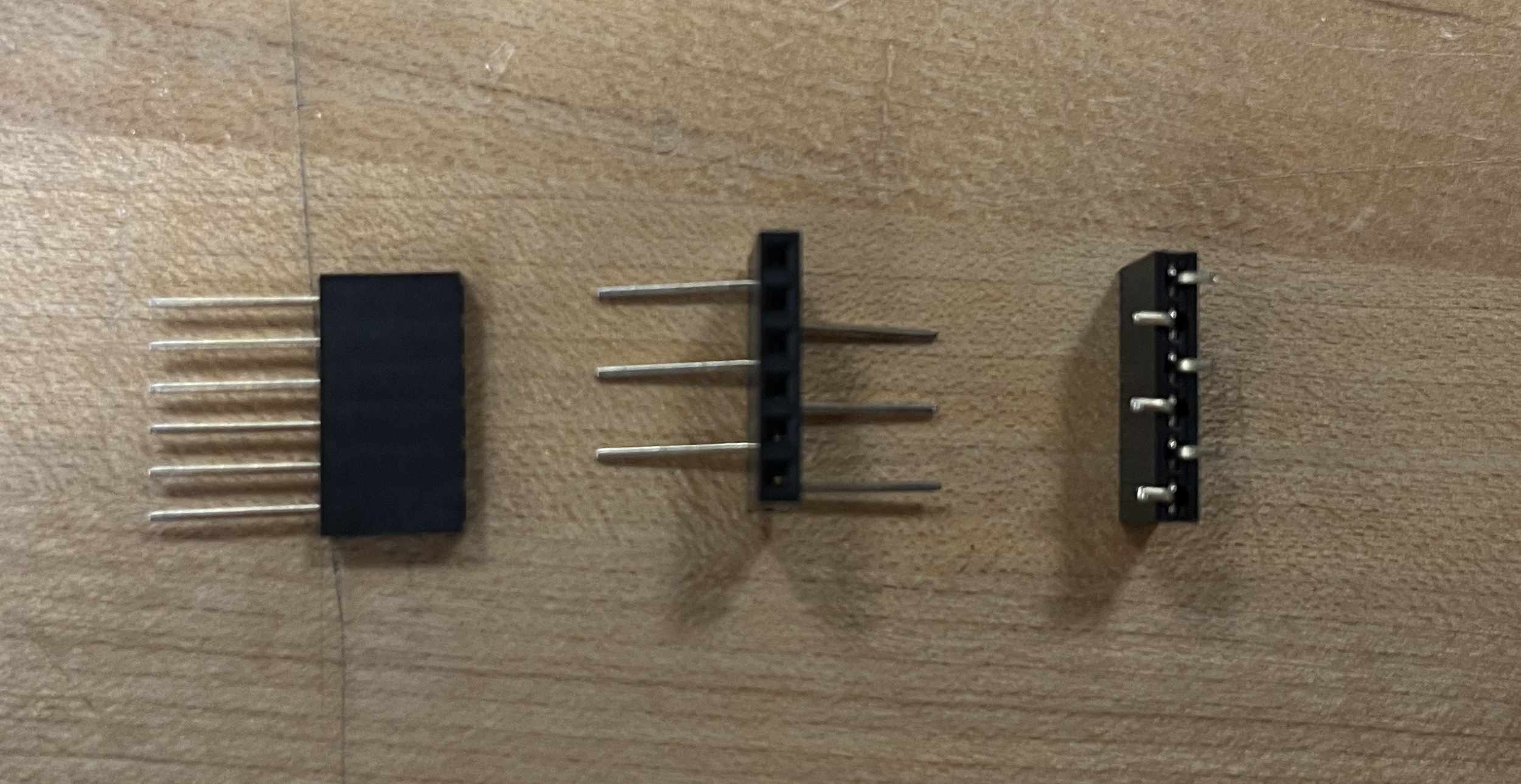
Challenge 0- How to Make In-House SMD Female Headers
Since the inventory didn’t include any SMD female headers, I had to find a workaround. Here’s the process I used:
- Prepare through-hole female headers with the desired pin number.
- Fold each pin 90 degrees along the zig-zag pattern like the footprint.
- Trim the excess length of each pin to fit in the SMD header footprint.
Challenge 1 - Logic Level Conversion:
One of the initial challenges I encountered was the difference in logic levels between the HX711 module (5V) and the XIAO ESP32S3 (3.3V). To bridge this gap, I employed a “Bi-Directional Logic Level Converter” to safely convert the 5V logic level to 3.3V, ensuring seamless compatibility between the components.
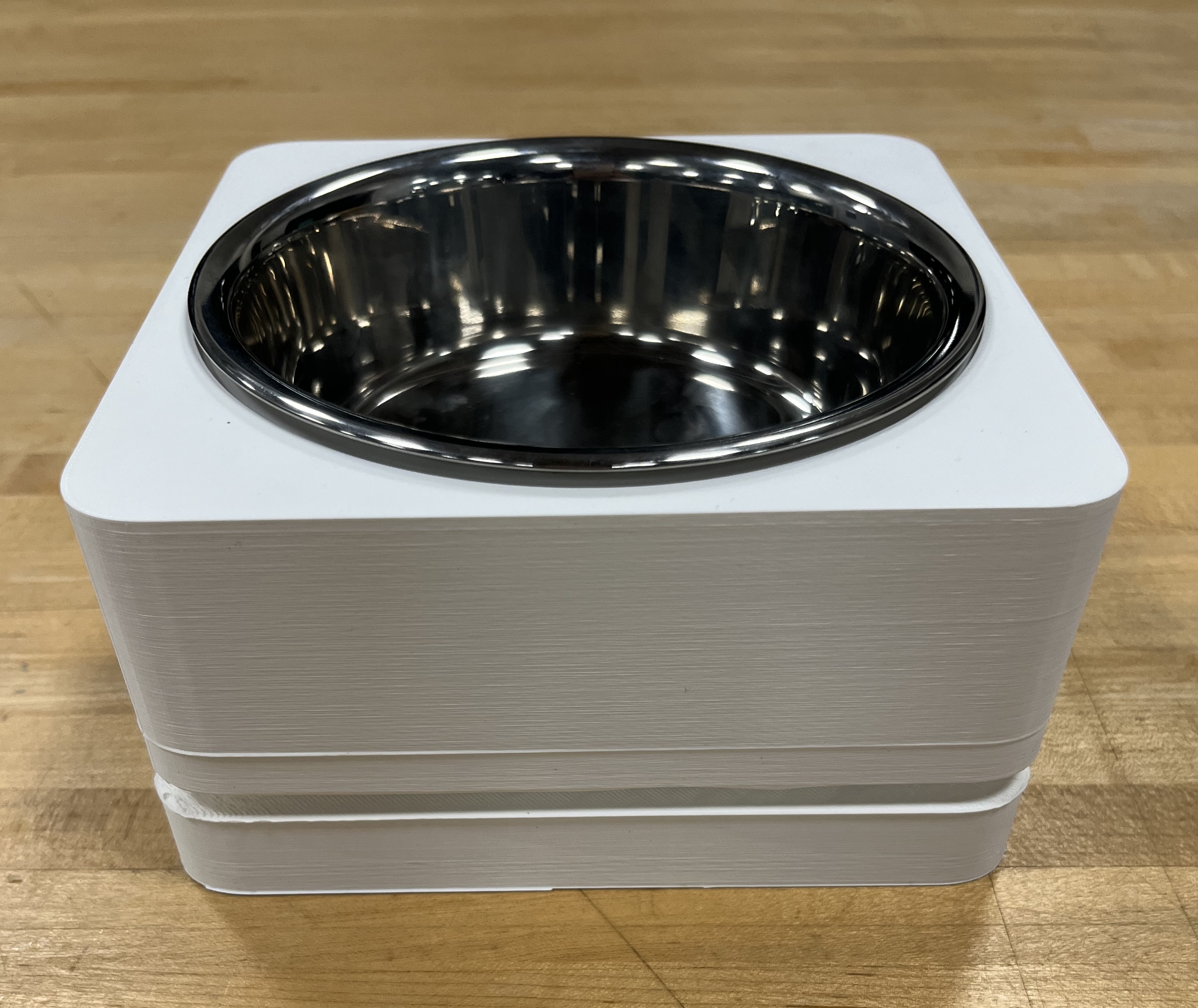
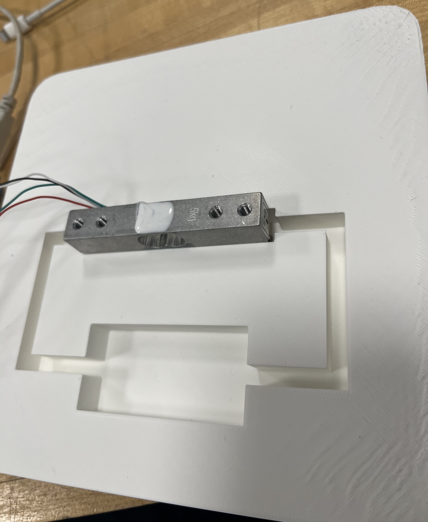
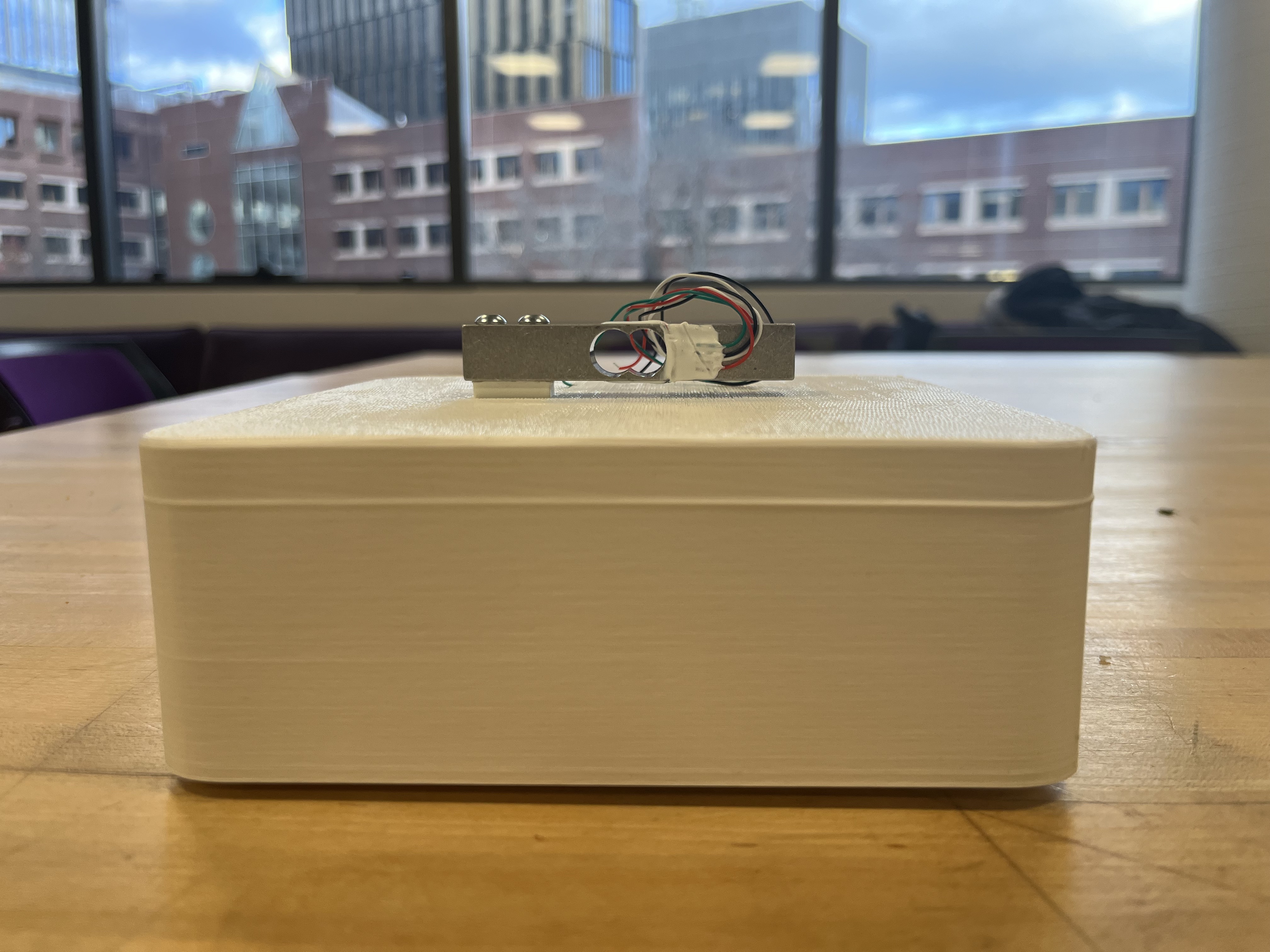
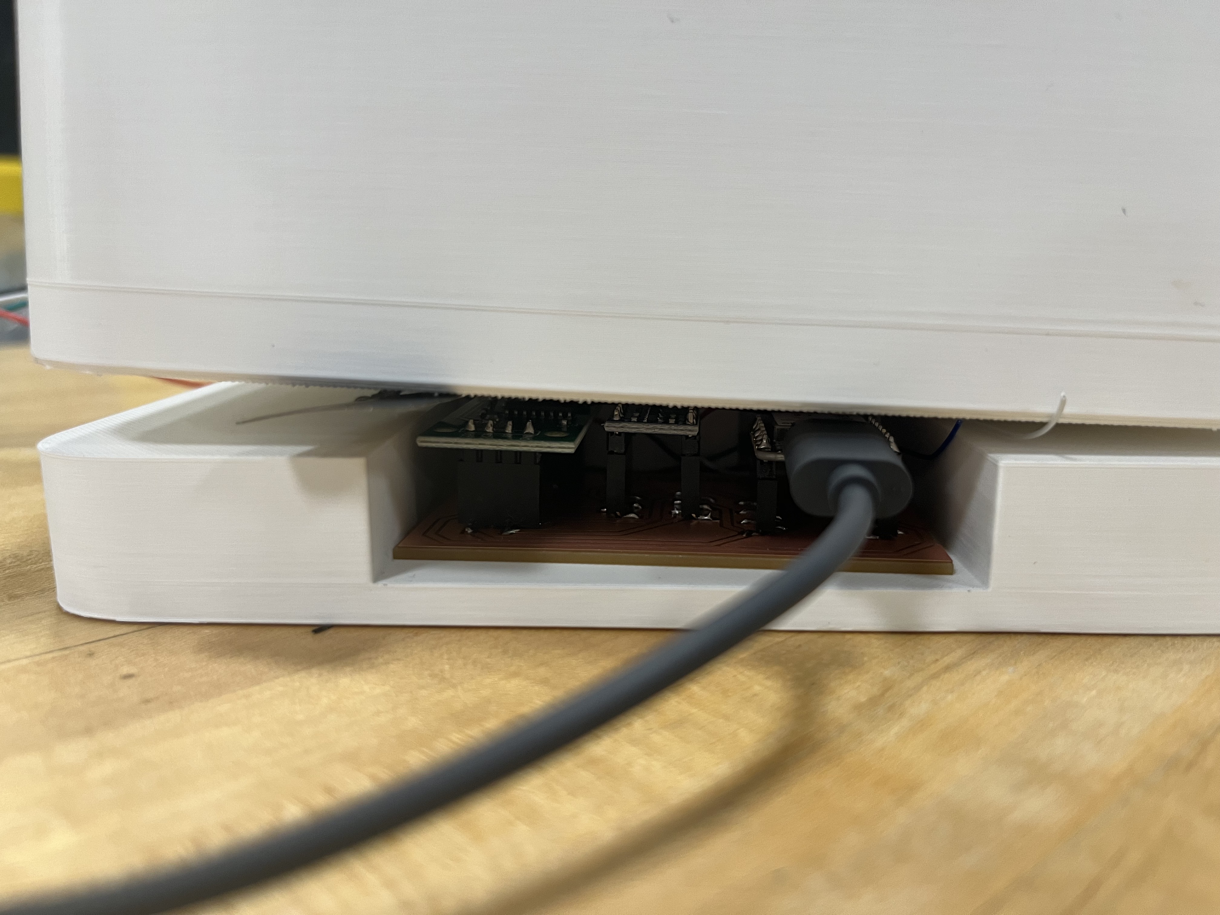
Challenge 2 - Load Cell Container Design:
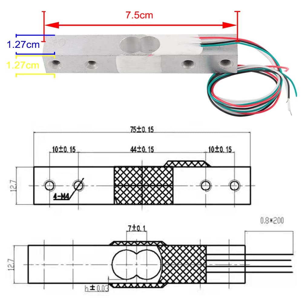
The load cell demanded a specific installation method, prompting the need to design a platform that adhered to the provided instructions. To address this, I crafted a custom dog bowl design with a slot precisely aligned with the load cell’s dimensions as specified in the datasheet. The initial iteration had some fitting issues, so I extended the slot to provide more room for the load cell’s movement, preserving its weighing accuracy.
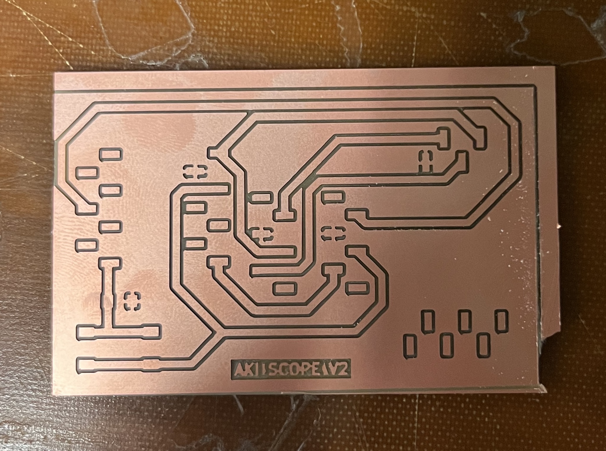
Challenge 3 - PCB Adaptability:
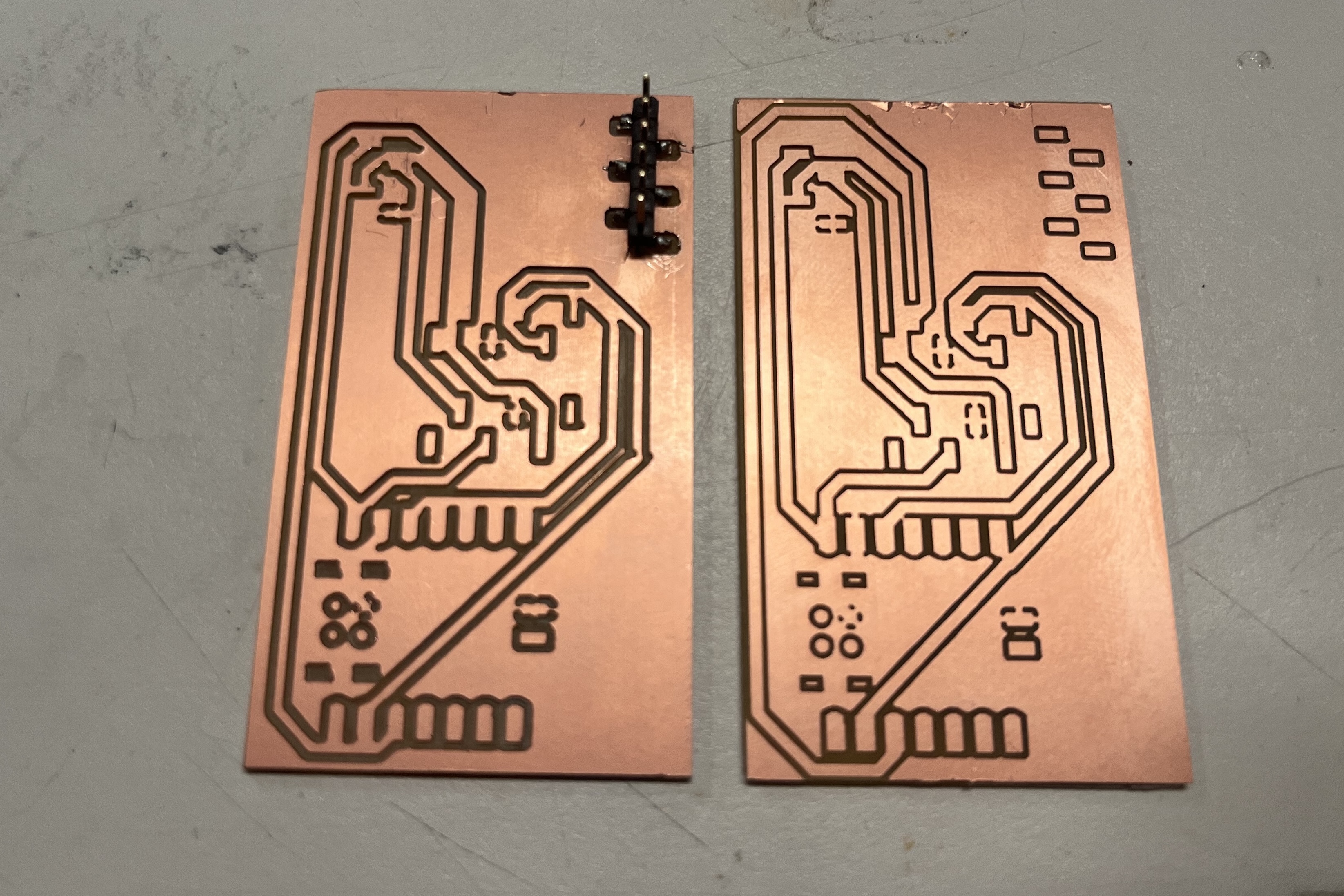
Given that the modules had through-hole pins, I initially designed the PCB with SMD male connectors because female SMD headers were not readily available in the lab. This design allowed for direct soldering of the male headers onto the PCB and modules. However, it posed challenges in terms of debugging and module replacement, as they were permanently soldered together.
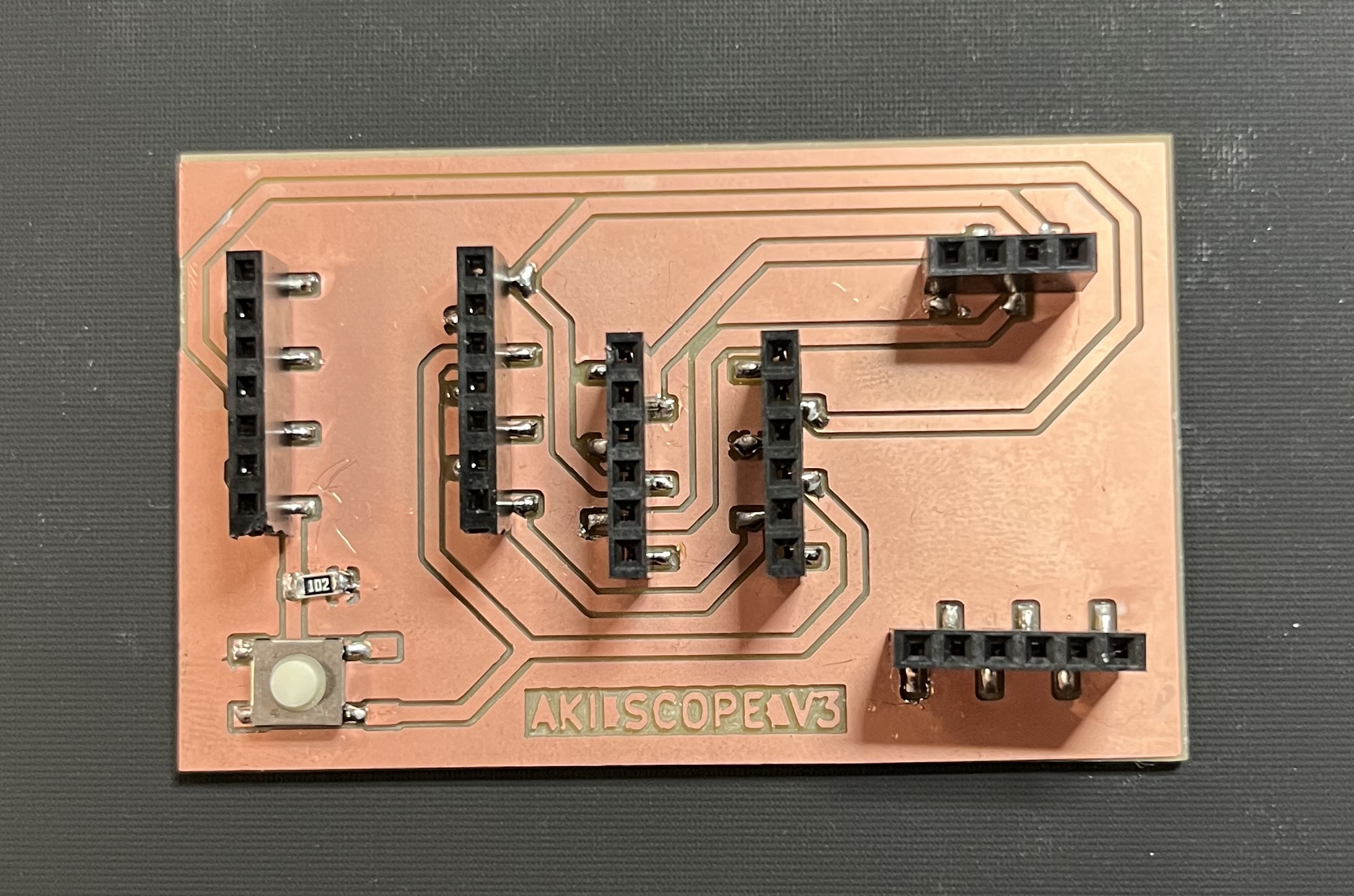
For enhanced flexibility and easier debugging in future projects, I devised a solution. In the second version of the PCB design, I opted for female headers, making it simple to swap modules and troubleshoot connections. This approach worked effectively, with one downside - the increased height of the PCB neared the limit of the 3D model’s housing.
Conclusion:
As my journey in circuit design unfolds, I continue to learn and adapt to the evolving challenges and opportunities presented by my projects. This week’s exploration not only introduced me to load sensors and the HX711 module but also showcased the importance of adaptability and creative problem-solving in the realm of electronics and PCB design. Stay tuned for more exciting updates as I explore the limitless possibilities of making almost anything through innovative circuit design!