In this week, we learn to code on XIAO rp2040.
Arduino IDE and Board Manager setup:
For starting, I follow the tutorial “Getting Started with Seeed Studio XIAO RP2040”.
-
Open the Arduino IDE & Navigate to Arduino IDE > Settings, and fill “Additional Boards Manager URLs” with the url below: https://github.com/earlephilhower/arduino-pico/releases/download/global/package_rp2040_index.json
-
Navigate to Tools > Board > Boards Manager, type the keyword “RP2040” in the search box, select “Rasberry Pi Pico/ RP2040”. Warning: Do not select “Seeed XIAO RP2040”(It is no longer available)
Neopixel testing:
After finishing setting up IDE and Board manager, I downloaded “Adafruit_NeoPixel” from Library Manager.(sketch > Include Library > Manage Libraries). And tested out the on-board Neopixel.
Library:
- Adafruit_NeoPixel
Code
  #include <Adafruit_NeoPixel.h>

  int Power = 11;
  int PIN  = 12;
  #define NUMPIXELS 1

  Adafruit_NeoPixel pixels(NUMPIXELS, PIN, NEO_GRB + NEO_KHZ800);

  void setup() {
    pixels.begin();
    pinMode(Power,OUTPUT);
    digitalWrite(Power, HIGH);

  }

  void loop() {
    pixels.clear();
    pixels.setPixelColor(0, pixels.Color(15, 25, 205));
    pixels.show();
    delay(200);
    pixels.clear();
    pixels.setPixelColor(0, pixels.Color(103, 25, 205));
    pixels.show();
    delay(200);
    pixels.clear();
    pixels.setPixelColor(0, pixels.Color(233, 242, 205));
    pixels.show();
    delay(200);
    pixels.clear();
    pixels.setPixelColor(0, pixels.Color(233, 23, 23));
    pixels.show();
    delay(200);
    pixels.clear();
    pixels.setPixelColor(0, pixels.Color(12, 66, 101));
    pixels.show();
    delay(600);
  }
It worked. Then I moved on to the next function testing.
OLED Display testing via I2C:
I used Grove - OLED Display 0.96” via I2C and display “Hello Wrold Hello Werold Hello Weirdo”.
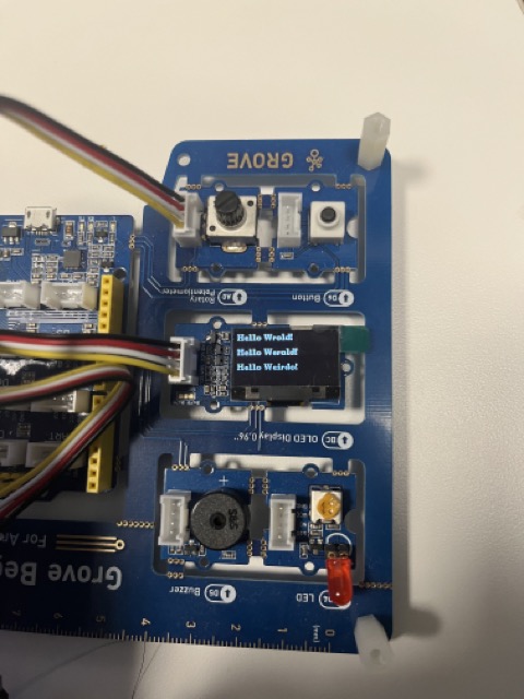
Connection:
I used default the SCL pin (PIN 5), the SDA pin(PIN 4) setup of XIAO RP2040. And coonected the ground and power VCC (3.3V) to provide power for the oled module.
Library:
- U8g2
Code:
  #include <Arduino.h>
  #include <U8g2lib.h>

  #ifdef U8X8_HAVE_HW_SPI
  #include <SPI.h>
  #endif
  #ifdef U8X8_HAVE_HW_I2C
  #include <Wire.h>
  #endif

  U8G2_SSD1306_128X64_NONAME_F_SW_I2C u8g2(U8G2_R0, /* clock=*/ SCL, /* data=*/ SDA, /* reset=*/ U8X8_PIN_NONE);

  void setup(void) {
    u8g2.begin();
  }

  void loop(void) {
    u8g2.clearBuffer();                   // clear the internal memory
    u8g2.setFont(u8g2_font_ncenB08_tr);   // choose a suitable font
    u8g2.drawStr(0,10,"Hello Wrold!");    // write something to the internal memory
    u8g2.drawStr(0,30,"Hello Werold!");
    u8g2.drawStr(0,50,"Hello Weirdo!");
    u8g2.sendBuffer();                    // transfer internal memory to the display
    delay(1000);
  }
Serial Input and Led Output
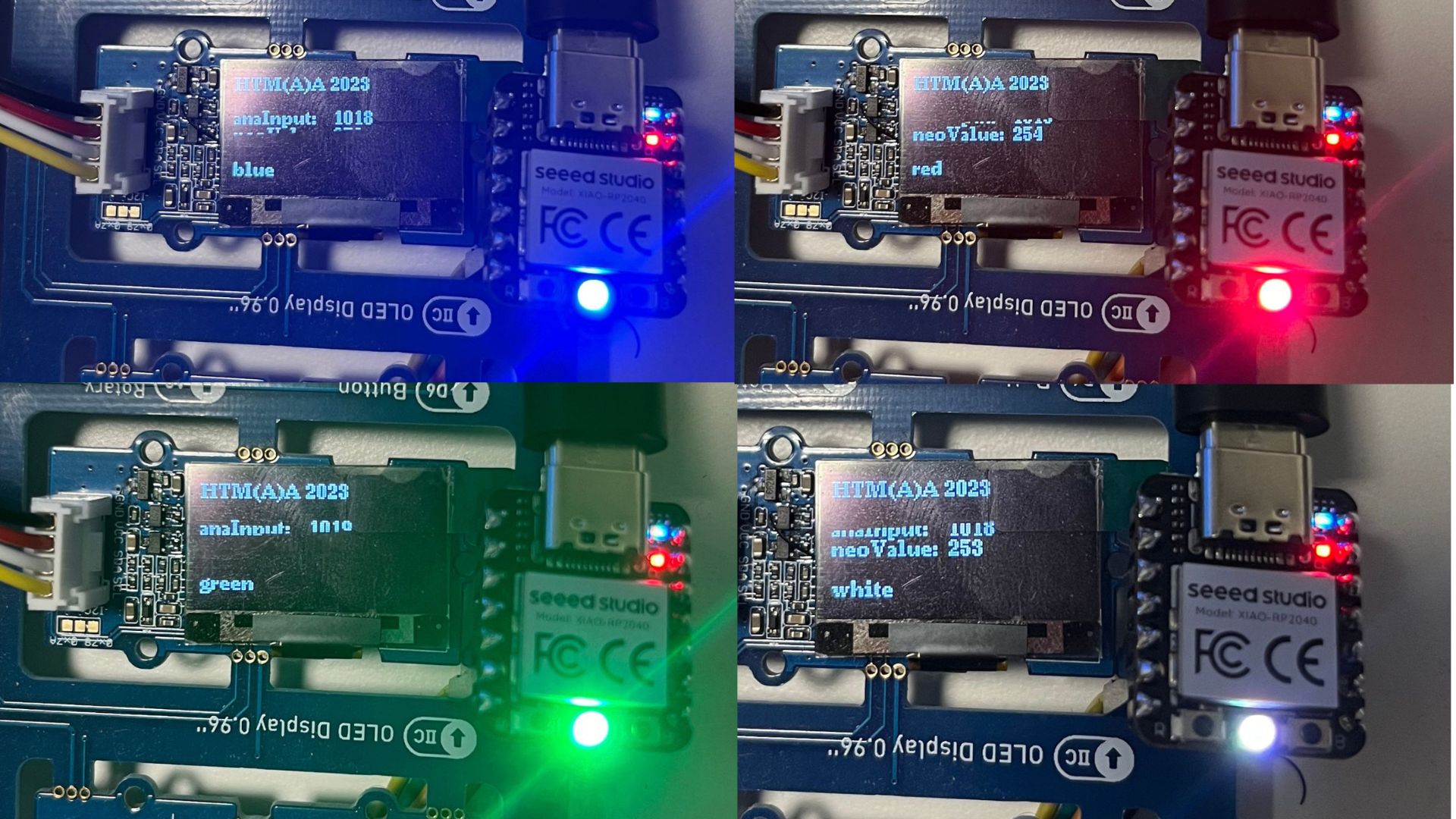
To finish this week’s assignment, I used Serial input to change colors of the Neopixel and a rotary angle sensor to change the brightness, and usdd OLED display to show the raw sensor value and current mapping brightness like the image above and the Video demo.
Circuit Overview
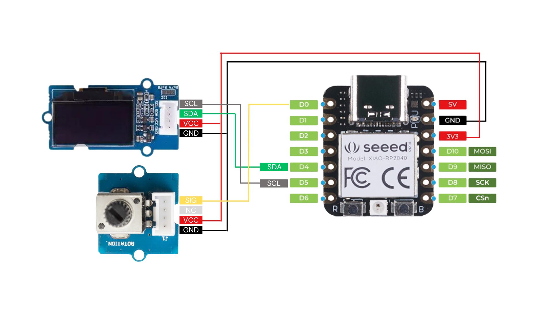
Connection
-
Module XIAO RP2040 OLED SDA SDA (PIN-4) OLED SCL SCL (PIN-5) GND GND VCC 3.3V Rotary SIG D0 (PIN-0)
Library
- Adafruit_NeoPixel
- U2g8
Code
  #include <Adafruit_NeoPixel.h>
  #include <Arduino.h>
  #include <Adafruit_NeoPixel.h>

  #ifdef U8X8_HAVE_HW_SPI
  #include <SPI.h>
  #endif
  #ifdef U8X8_HAVE_HW_I2C
  #include <Wire.h>
  #endif
  U8G2_SSD1306_128X64_NONAME_F_SW_I2C u8g2(U8G2_R0, /* clock=*/ SCL, /* data=*/ SDA, /* reset=*/ U8X8_PIN_NONE);

  int Power = 11;
  int PIN  = 12;
  #define NUMPIXELS 1
  Adafruit_NeoPixel pixels(NUMPIXELS, PIN, NEO_GRB + NEO_KHZ800);

  const int sensorPin = A0;
  int sensorValue = 0;
  int neoValue = 0;
  int neoType = 0;
  char neoColor[] = "no light";

  void setup() {
    Serial.begin(9600);

    pixels.begin();
    pinMode(Power,OUTPUT);
    digitalWrite(Power, HIGH);

    u8g2.begin();

    // declare the ledPin as an OUTPUT:
    pinMode(sensorPin, INPUT);
  }

  void loop() {
    // read the value from the sensor:
    sensorValue = analogRead(sensorPin);
    neoValue = map(sensorValue, 0, 1023, 30, 255);
    serialHandle();
    neoUpdater();
    oledUpdater();
    Serial.println(neoValue); //0-1023}
  }

  void serialHandle(){
    if (Serial.available() > 0) {
      int inByte = Serial.read();

        switch (inByte) {

          case 'r':
            strcpy(neoColor,"red");
            neoType = inByte;
            pixels.clear();
            pixels.setPixelColor(0, pixels.Color(neoValue, 15, 15));
            pixels.show();
            break;

          case 'g':
            strcpy(neoColor,"green");
            neoType = inByte;
            pixels.clear();
            pixels.setPixelColor(0, pixels.Color(15, neoValue, 15));
            pixels.show();
            break;

          case 'b':
            strcpy(neoColor,"blue");
            neoType = inByte;
            pixels.clear();
            pixels.setPixelColor(0, pixels.Color(15, 15, neoValue));
            pixels.show();
            break;

          case 'w':
            strcpy(neoColor,"white");
            neoType = inByte;
            pixels.clear();
            pixels.setPixelColor(0, pixels.Color(neoValue, neoValue, neoValue));
            pixels.show();
            break;

          case 'e':
            strcpy(neoColor,"no light");
            neoType = inByte;
            pixels.clear();
            pixels.show();
            break;

          default:
            pixels.show();
        }
    }
  }

  void neoUpdater(){
    switch (neoType) {

      case 'r':
        pixels.clear();
        pixels.setPixelColor(0, pixels.Color(neoValue, 15, 15));
        pixels.show();
        break;

      case 'g':
        pixels.clear();
        pixels.setPixelColor(0, pixels.Color(15, neoValue, 15));
        pixels.show();
        break;

      case 'b':
        pixels.clear();
        pixels.setPixelColor(0, pixels.Color(15, 15, neoValue));
        pixels.show();
        break;

      case 'w':
        pixels.clear();
        pixels.setPixelColor(0, pixels.Color(15, 15, 15));
        pixels.show();
        break;

      case 'e':
        pixels.clear();
        pixels.show();
        break;

      default:
        pixels.show();
    }
  }

  void oledUpdater(){
    u8g2.clearBuffer();                   // clear the internal memory
    u8g2.setFont(u8g2_font_ncenB08_tr);   // choose a suitable font
    u8g2.drawStr(0,10,"HTM(A)A 2023");    // write something to the internal memory

    u8g2.drawStr(0,30,"anaInput: ");
    u8g2.setCursor(60, 30);
    u8g2.print(sensorValue);

    // uint32_t color = pixels.getPixelColor(0);
    u8g2.drawStr(0,40,"neoValue: ");
    u8g2.setCursor(60, 40);
    u8g2.print(neoValue);

    //u8g2.drawStr(0,60,"test light ");
    u8g2.setCursor(0, 60);
    u8g2.print(neoColor);


    u8g2.sendBuffer();                    // transfer internal memory to the display


    Serial.println(neoValue);
    delay(1000);
  }
Mu Editor and CircuitPython
I also tried using different language(CircuitPython) and development environments(Mu Editor). I follow the instruction fromSeeed Studio XIAO RP2040 with CircuitPython
-
Download Mu Editor and Prepare firmware for RP2040 given by the instruction.
-
Check the disk drive if the name has changed to “CIRCUITPY”
- Paste the code
"""Example for Pico. Blinks the built-in LED.""" import time import board import digitalio led = digitalio.DigitalInOut(board.LED) led.direction = digitalio.Direction.OUTPUT while True: led.value = True time.sleep(0.5) led.value = False time.sleep(0.5) - Save the file as “code.py” to the drive (“CIRCUITPY”)