The fourth circuit board we're making!
This week, we had to make a circuit board that would connect to an output device. I chose to work with a stepper motor.
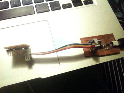
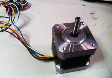
I had not much time to design the board this week, so I opted to use Neil's board. I chose the unipolar stepper motor because eventually I want to relate sound to motor orientation. For more info on the differences of motors, I found this page really useful.
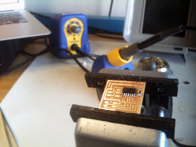
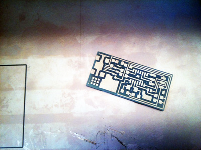
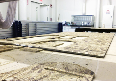
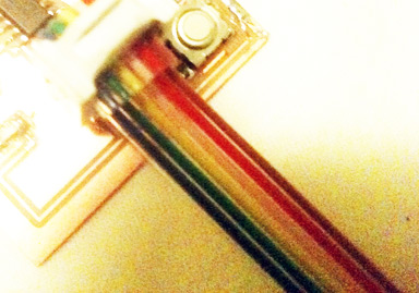
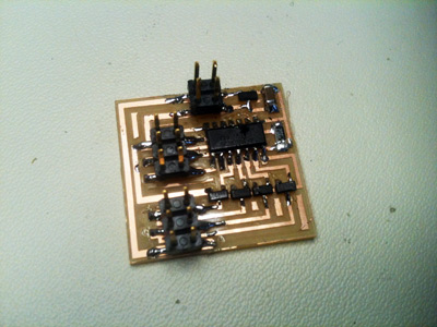
I milled the board as usual on the Modela machine. I went really smooth. It helps to remember the basics, ie. the main thing is to keep the platform really really flat. And to make sure the end mill is neither screwed loosely nor too tight. I proceeded to select the parts needed and soldered them onto the board. I'm still not super good at it, but I'm getting faster and better. This time the board didn't need debugging, it worked well on my first time!
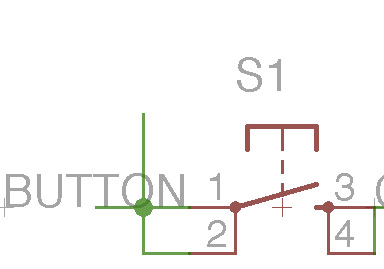
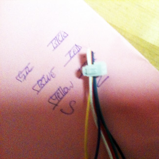
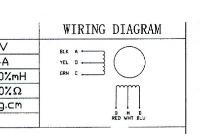
Once the board was ready, I picked the unipolar stepper motor. I used the Jameco 238538 that has a 12V. I found out that voltage of the battery powering the board doesn't need to fit the voltage of the motor. So I used a 9V battery. The tricky part was to have the right pins correspond to the board's pins. The colors indications were different between Neil's board and the motor. So with Rob Hemsley's help (our TA this week), I was able to connect the motor to the right pins. We used the data sheet of the motor and a couple of webspages for reference (1) (2). As a summary, for Neil's board and this motor, the pins are top line, left to right, Black - Red - White, bottom line, left to right Green - Blue - Yellow. White and Yellow are interchangeable.
Next you need to program the board. Again, not much time for tinkering this week. I mainly cared to test if the board was working, so I used Neil's script. I used my Fab ISP programmer (first board we made) to connect the output board to the Arduino interface. As usual, the steps are : checking that you're using the right programmer (in this case Tools>Programmer>USBTinyISP), then choosing the right board (in this case Tools>Board>ATtiny44, Internal 8Mhz Clock),then burn the bootloader (in Tools as well). Finally I've to make sure I upload the program using the programmer (in File).
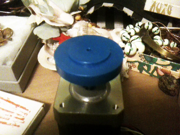
Final part: I added a wheel on top of the motor I usually use in workshop to better show that the motor was indeed spinning.

Week 10
Week 11

Week 12

Week 13

Week 14

Week 15
Week 16