Because everything is designed at some point, even a circuit board
As a follow up to the previous electronics session, we had to make a board that this time we designed, that would include a LED and a switch
The first task is really to apprehend the main tool for designing the board, which is the software Eagle. Luckily, there was a one hour tutorial session during the week that was very helpful to understand how the software works and how to use the interface in the best way. Eagle is not super intuitive, but once you get some explanations, it's not a mean software and it ends up being rewarding.
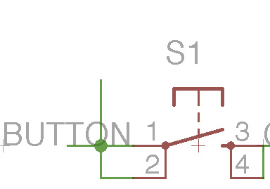
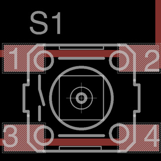
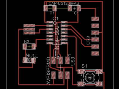
Next up is the design itself. We had a couple of examples we could emulate which proved essential. But mostly what I found really nice is that in my little experience with electronics, I never really questioned the role of each parts. I knew roughly what they were for, but this time, I really got interested in how they relate to each other, how they connect, what they do. So as you place the elements on the Eagle schematics interface, it ends up being quite smooth. Of course, it helps if like me, there was a TA around that I could check with every time if I wasn't making mistakes.
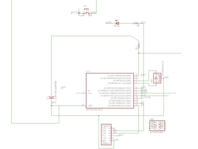
You have to export the schematics into a board, and this is where the "fun" begins by actually making the connections between the different parts. I believe this is where you can get really creative, challenge your design to be super small or pretty or inventive. I played it somewhat safe, but I hope to think that I kept it elegant. Also I liked to keep an overall square shape. At the end you export two parts, the board and a contour to send it to the CNC milling machine for cutting.
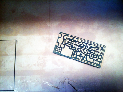
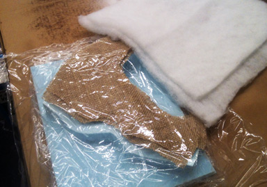
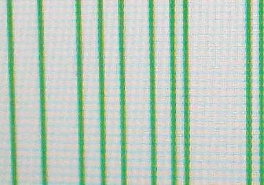
Similar to the previous session, the CNC Modela machine is quite straightforward. The settings are always a bit tricky from cut to cut, but this time I was lucky, it worked like a charm the first time. Because some lines in my board were really close to each other, I used a smaller diameter (2) in order to make the lines appear in the paths. I care to check always that the board is really flat on the mill, that the tool is neither loose nor too tight and that it's positioned right on the board.
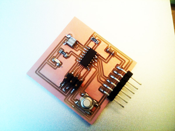
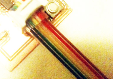
The last part is soldering the components onto the circuit board. As always, I really enjoy this part because it is so meditative. But I must say that it's killing my eyes, because the components are really tiny. Lots of light help but I don't find the magnifying glass very handy. Also I wish the twizzers were smaller...
Week 10
Week 11

Week 12
Week 13
Week 14

Week 15
Week 16