Smart Desk Lamp
Summary
For this project I:
- Designed the parts of the Lamp in Fusion 360.
- Designed the schematics for my main board and my sensor boards in Eagle.
- Created capacitive electrodes for Capacitive Buttons (touchless buttons with step response TxRx).
- Programmed with C the microcontroller.
- Connected the sensors in a asyncronous network to control light intensity.
- Machined the wood in the Shopbot.
- Create an interface to communicate between the computer and the lamp via bluetooth.
- Laser Cut the body of the device.
- 3D Print the lamp shade.
- If you are interested in creating good capacitive electrodes, I recomend reading the following Atmel tutorial.
After realizing that it was almost impossible to finish on-time, i decided to change and reduce the scope of the project. I would only design one of the fuctions of the lamp. I decided to design the external light or flag that would let people know if you are busy and dont want to be disturbed or open to conversations..
Design objective - The complete SmartLamp
what does it do?
Is a lamp that let you send a signal to your peers if you are busy and do not want to be disturbed.
who's done what beforehand?
There are a couple of companies that seel this devices like LUXAFOR and KUANDO. The price varies between $20 USD and $50 USD.
what did you design?
I designed all the components of the lamp, from the packagint to the boards.
what materials and components were used?
Playwood, PLC Platic, Copper.
where did they come from?
All the components came from the fab lab inventory and scraps from the architecture lab.
how much did they cost?
Do not disturb light
| Name | Description | Price |
|---|---|---|
| Microcontroller | AVR Attiny 44 | 1.50 |
| Copper Tape | 3M #1126 copper tape with conductive adhesive 6"x36 yds @. | 1.00 |
| Copper Boards | Copper board for milling circuit boards. | 1.00 |
| Epoxy Film | 3M #1 epoxy film on liner 6"x100 yds @. | 1.00 |
| 4.50 | ||
what parts and systems were made?
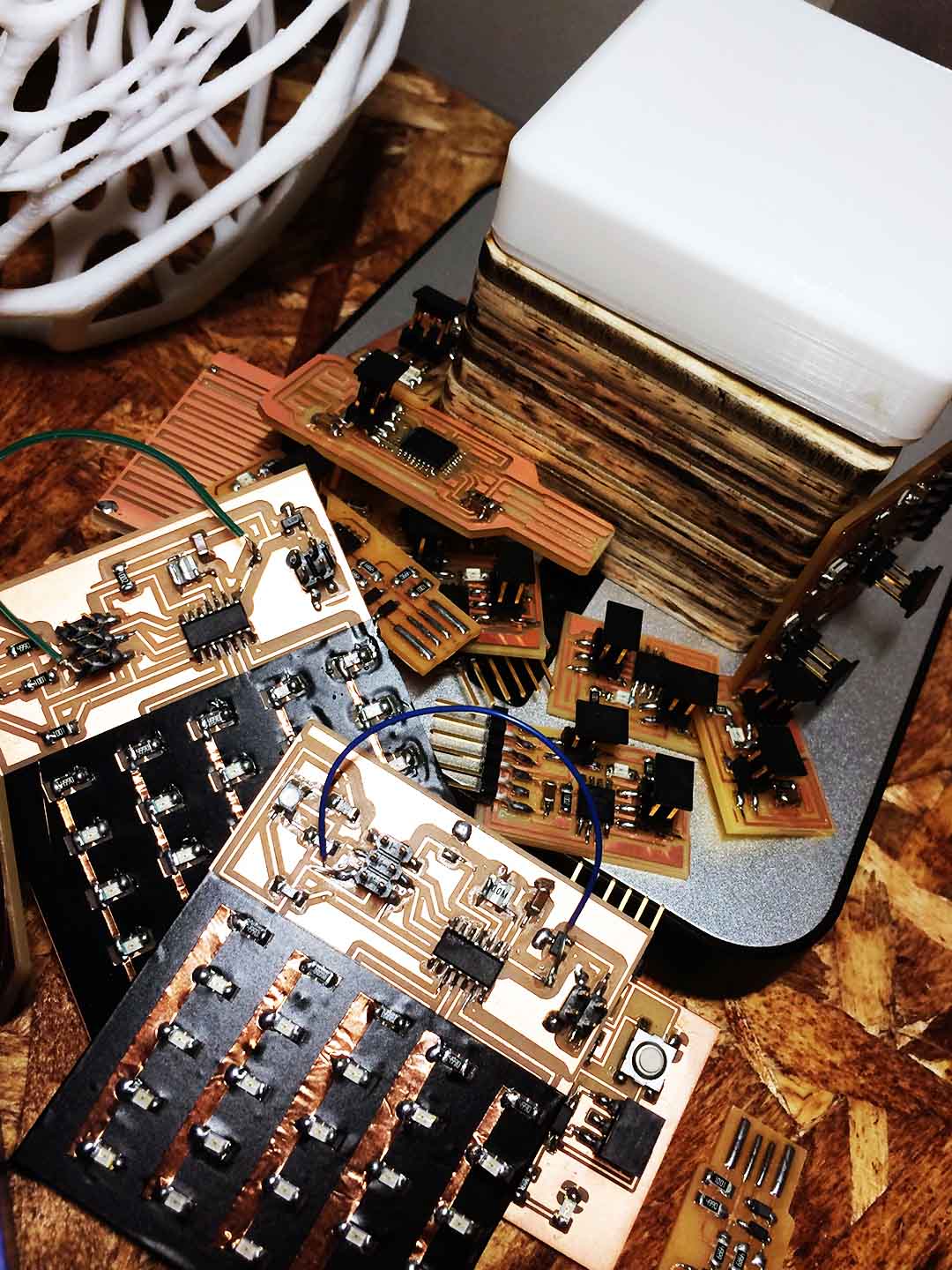
I created the main board, the RGB LED board, two capacitive electrodes, the packaging and the lamp shade
what processes were used?
3D modeling in Fusion 360, Electronic Design in Eagle, 3D printing, Laser cutting, Milling and Soldering.
what questions were answered?
How to create a capacitive sensor electrode?, how to use the ADC module in the microcontroller?, how to design a device?
how was it evaluated?
The lamp works if you are able to signal other people that you are busy
Design objective - The complete SmartLamp
Two main trends inspired me to design my final project proposal. 1. The open office trend which companies have adopted have created problems for people to concentrate since they found themselfs interrupted by their peers constantly. 2. IoT is becoming more and more important but is not only about what we measure but what do we do with the things that we measure.
My ideal SmartLamp will let you control the light intensity, let you know the conditions of your work envieronment and give external signals when you do not want to be disturbed. This first version of my Smart Lamp will only implement the third function, a future iteration will cover the first and second functions.
Design on Fusion 360
I have become very familiar with Fusion 360. I discovered the easy that is to simulate, test and even assemble your model, test it and make changes in one applicatio. Fusion 360 is easy when you get used to its platform, but is important to have some desing workflow, otherwise if you do not follow a structured workflow it can become almost imposible to later adjust your design for little things like the thick of your material and other things like that.
To design my lamp I followed a Top Down Strategy, you can find a nice tutorial in the link and also in Fusion 360 Official YouTube page there are a lot of good tutorials.
Finally, instead of having a sensor module, I decide to include the boards inside the lamp. My design will consist of:
Electronics
- Main Board: this board will control the light intensity of the lamp and will turn on and off the whole lamp. It will also control the "Do not distrub" LED.
- 40 Sensor boards: 40 sensors board whith a capacitive button that will control each of the LEDs of the lamp.
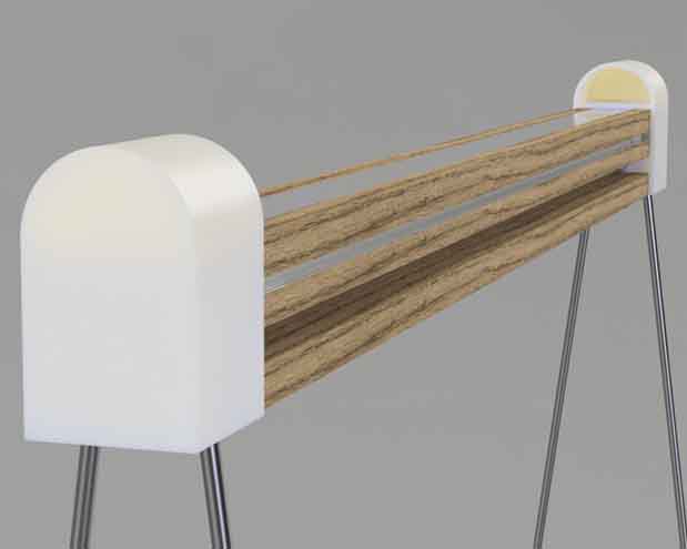
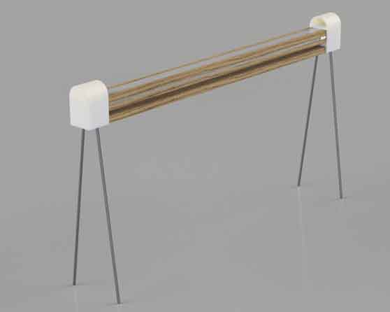
Body of the lamp
- Wood sheets: I am thinking that Oak will be the best wood to use because of its properties.
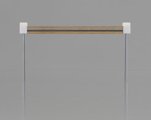
- Metal tube: the tube will help the lamp to have some movement, it will keep in position by friction only.
Reducing the scope of the project and redesigning again.
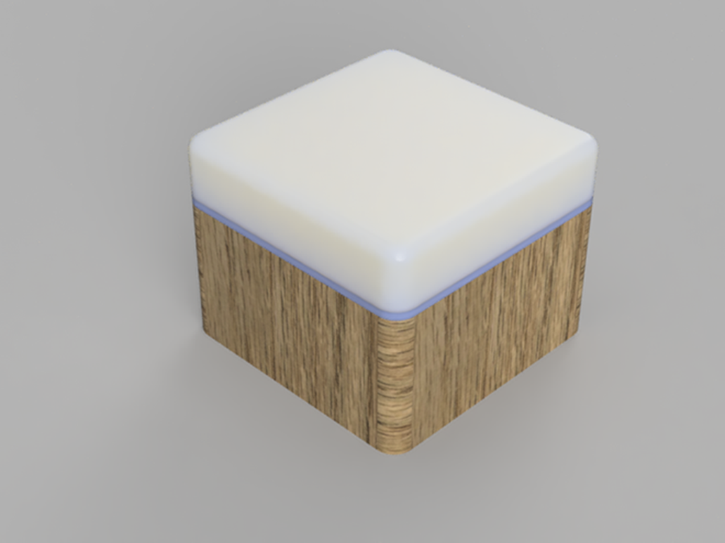
After thinking what was realistically possible to finish with the time that I had, I decided to focus my attention to only on the do not disturb light. Although it is a very simple project I wanted to make a visual interesting project that was simple but that at the same time would be appealing.
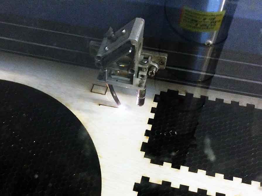
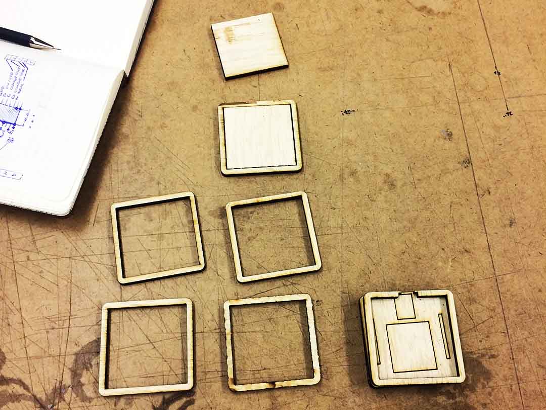
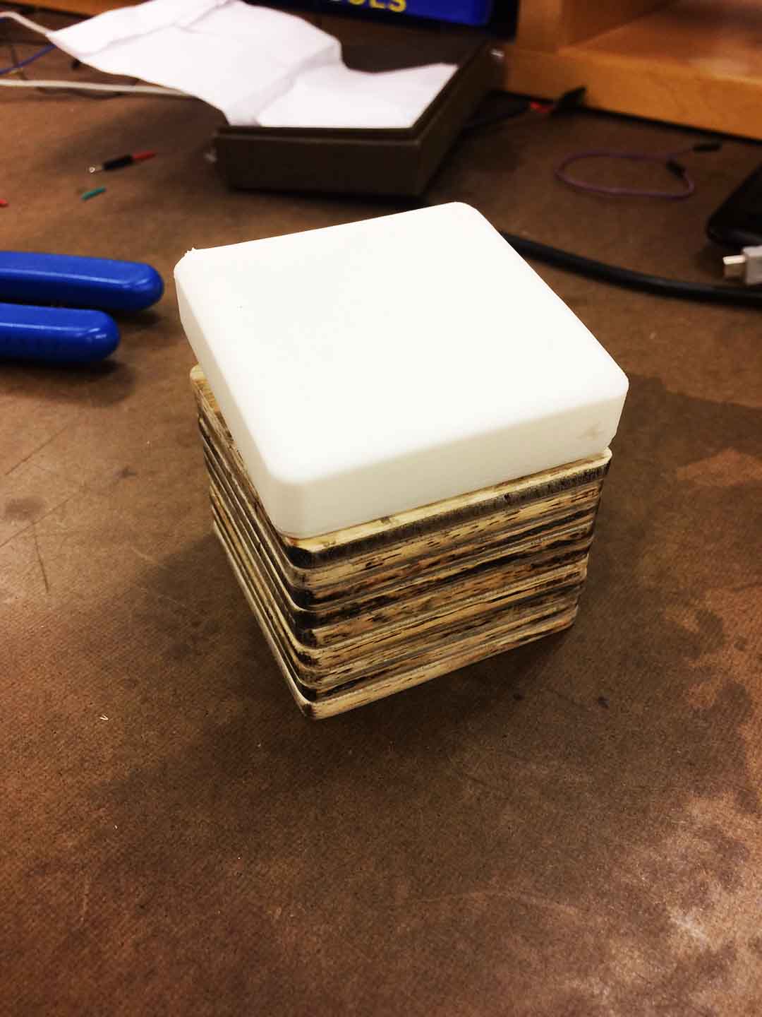
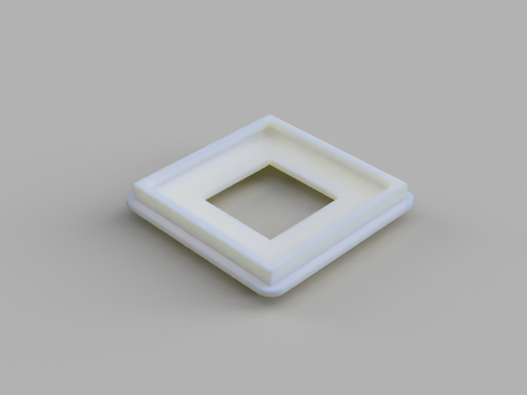
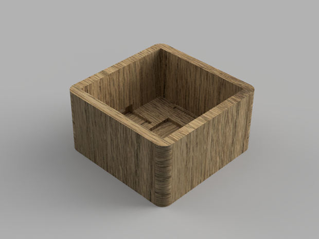
To create this, I decided to mix two materials plastic and wood. Since the box is two small and the thickness would be only 3mm I decided to LaserCut the material and 3D print the plastic shade. For the design I used Fusion 360.
The design is simple but take into account:
- Space to fit the boards and sensor.
- USB connection to power the device and future communication.
Electronic Design
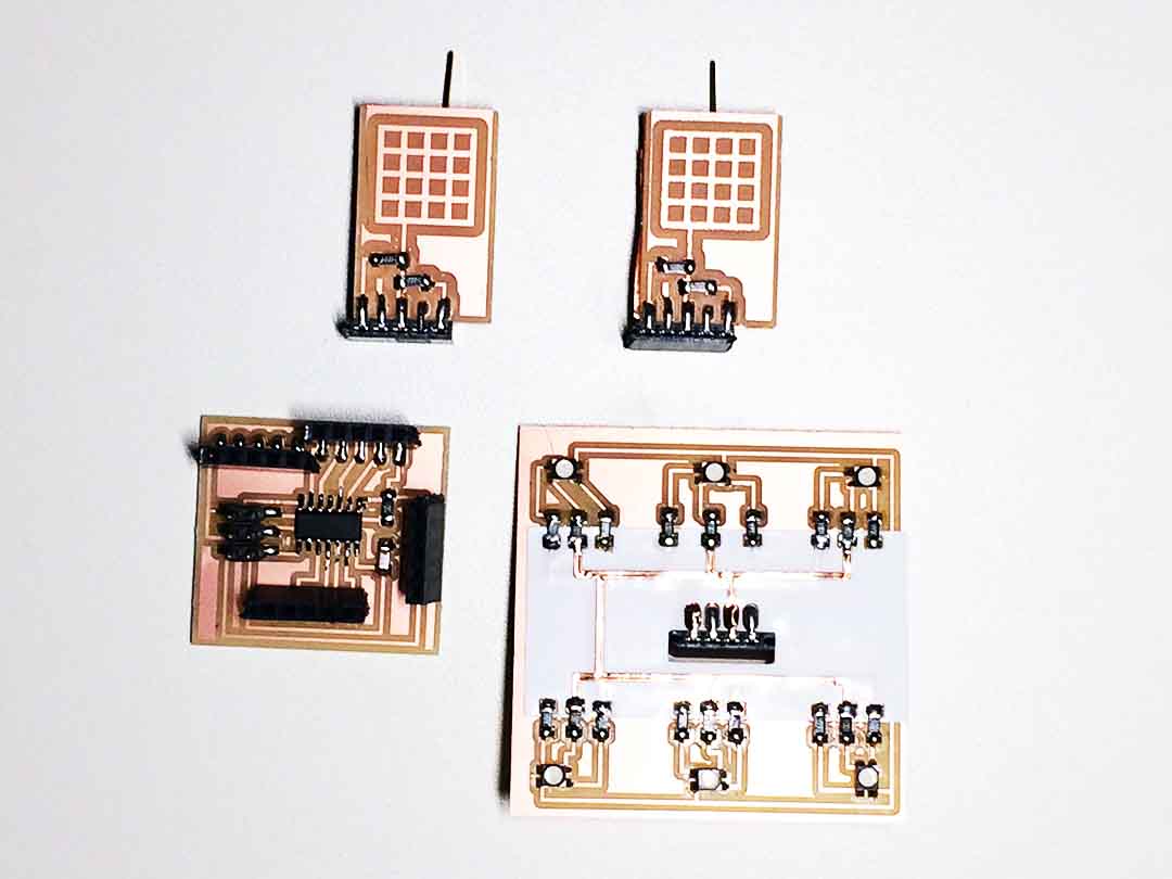
For the desing of the electronics I used Eagle and Photoshop. I had to design: 1) The main board for the Attiny44. 2) The light board where I the RGB LED's would be. 3) Two mutual capacitive electrodes.
Main Board and RGB LED Board
Since I was also prototyping I decided to create a board that was gave enough flexibility to plug an unplug things to different pins. To maintain the simplicity of RGB LED's board I used 3 layers to eliminate the 0 Ohms resistors.
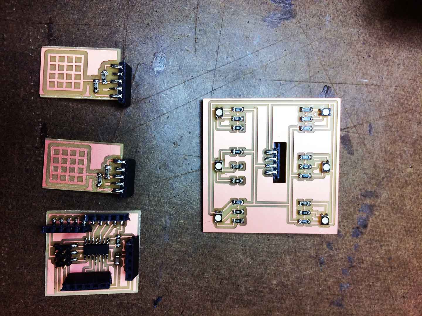
Capacitive Sensor
To get the correct capacitive sensor can be very tricky. Although the design can be very simple, there are many rules to follow to create a good capacitive electrode.
If you are in your path to build a capacitive sensor, I strongly recommend that you read this Sensor Tutorial. Basically there are two types of sensors:
- Self-capacitive sensor: If you follow Neil's Step Load Board you can build this type of sensor. The good thing is that is preety easy to build. The bad thing is that the sensor depends on the envieronment circunstances, could give you false positives.
- Mutual-capacitive sensor: based on Neil's Trasmit-Receive model. This model is more reliable. The bad thing is that the electrodes are very difficult to design correctly.
First try
This week I tried three types of sensors, but non of them worked as expected. I am going to try to make them a little bit bigger.
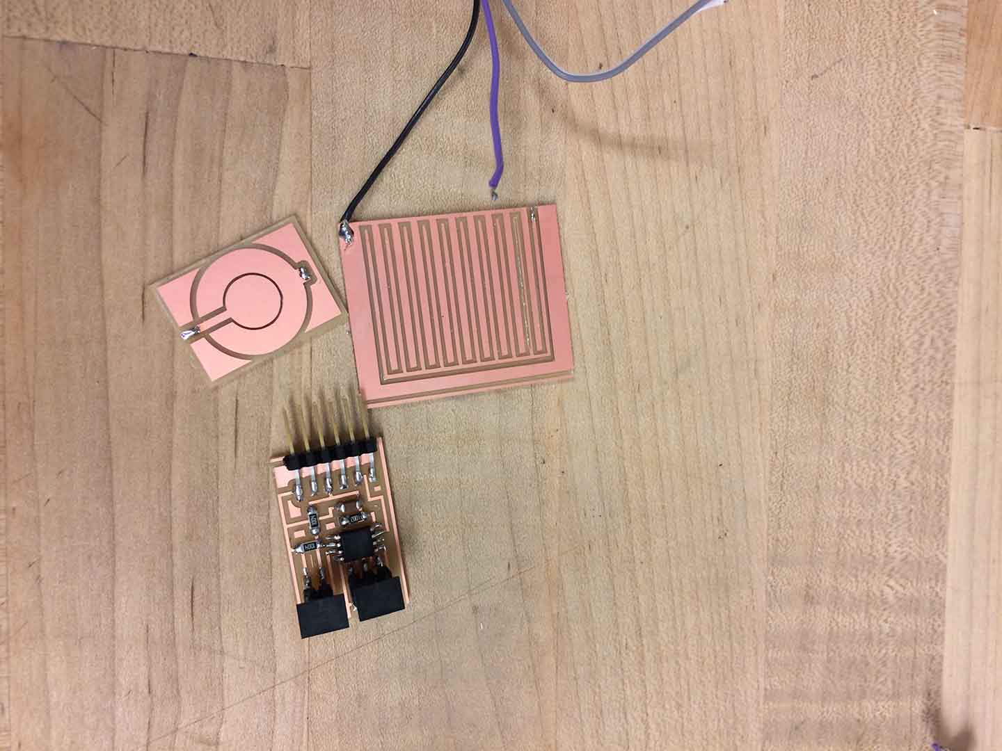
Second Try
Finally this week I manage to get it correctly. The trick is in two things:
- The resistor: the higher the value of the resistor the more sensitive the sensor is (but also the possible noise). For my sensors I changed the resistor from 1MOhms to 4MOhms.
- The design: The Tx area most overflow the Rx Area. The Rx paths must create a "net". All the details are explained in Atmel's tutorial. Since Eagle does not provide a library for Capacitive Electrodes, it is better to design them in a design software.
Embedded Programming
To programm the microcontroller I used C. To programm the microcontroller is important to understand all of the funtions and the things and variables that the microcontroller is reading. I recommend the following Microcontroller Tutorial.
My code is base on Neil's TxRx code and Shirin Shivaei code. It uses the Analog to digital conversion module from the Attiny44. The at44 only have one ADC module and since I am using two capacitive buttons is important to understand that the ADC module can not convert both signals simultaneously. In the code loop you can see that first we are reading for one sensor and then from another one. To do this you have to adjust the ADMUX to read from the pin you want to read from.
In my code I am using PA2 and PA7 which can be adjusted like this:
- ADMUX = (0 << REFS1) | (0 << REFS0) // Vcc ref | (0 << MUX5) | (0 << MUX4) | (0 << MUX3) | (0 << MUX2) | (1 << MUX1) | (0 << MUX0); // PA2 Rx port for the sensor
- ADMUX = (0 << REFS1) | (0 << REFS0) // Vcc ref | (0 << MUX5) | (0 << MUX4) | (0 << MUX3) | (1 << MUX2) | (1 << MUX1) | (1 << MUX0); // PA7 Rx port for the sensor
#include < avr/io.h>
#include < util/delay.h>

#define output(directions,pin) (directions |= pin) // set port direction for output
#define set(port,pin) (port |= pin) // set port pin
#define clear(port,pin) (port &= (~pin)) // clear port pin
#define pin_test(pins,pin) (pins & pin) // test for port pin
#define bit_test(byte,bit) (byte & (1 << bit)) // test for bit set
#define bit_delay_time 102 // bit delay for 9600 with overhead
#define bit_delay() _delay_us(bit_delay_time) // RS232 bit delay
#define half_bit_delay() _delay_us(bit_delay_time/2) // RS232 half bit delay
#define settle_delay() _delay_us(100) // settle delay
#define char_delay() _delay_ms(10) // char delay
#define nloop 100 // loops to accumulate

#define serial_port PORTA
#define serial_direction DDRA
#define serial_pin_out (1 << PA3)
#define transmit_port PORTA
#define transmit_direction DDRA
#define transmit_pin (1 << PA0)
#define transmit_port2 PORTA
#define transmit_direction2 DDRA
#define transmit_pin2 (1 << PA1)

void put_char(volatile unsigned char *port, unsigned char pin, char txchar) {
//
// send character in txchar on port pin
//    assumes line driver (inverts bits)
//
// start bit
//
clear(*port,pin);
bit_delay();
//
// unrolled loop to write data bits
//
if bit_test(txchar,0)
	set(*port,pin);
else
clear(*port,pin);
bit_delay();
if bit_test(txchar,1)
	set(*port,pin);
	else
	clear(*port,pin);
bit_delay();
if bit_test(txchar,2)
set(*port,pin);
else
clear(*port,pin);
bit_delay();
if bit_test(txchar,3)
set(*port,pin);
else
clear(*port,pin);
bit_delay();
if bit_test(txchar,4)
set(*port,pin);
else
clear(*port,pin);
bit_delay();
if bit_test(txchar,5)
set(*port,pin);
else
clear(*port,pin);
bit_delay();
if bit_test(txchar,6)
set(*port,pin);
else
clear(*port,pin);
bit_delay();
if bit_test(txchar,7)
set(*port,pin);
else
clear(*port,pin);
bit_delay();
//
// stop bit
//
set(*port,pin);
bit_delay();
//
// char delay
//
bit_delay();
}


int main(void) {
//
// main
//
static unsigned char count;
static uint16_t up,down,up2,down2;
static int16_t lastup,lastdown,lastup2,lastdown2;
static int16_t deltaup,deltadown,deltaup2,deltadown2;// to track changes between loops
static int16_t diff, diff2;
static uint16_t upS,downS,upS2,downS2;
int pressedo =0;
int pressedc =0;
//
DDRB |= 1 << PINB0;
PORTB ^= 1 << PINB0;
DDRB |= 1 << PINB1;
PORTB ^= 1 << PINB1;
DDRB |= 1 << PINB2;
PORTB ^= 1 << PINB2;

PORTB ^= 1 << PINB0;
_delay_ms(100);
PORTB ^= 1 << PINB0;
//
// set clock divider to /1
//
CLKPR = (1 << CLKPCE);
CLKPR = (0 << CLKPS3) | (0 << CLKPS2) | (0 << CLKPS1) | (0 << CLKPS0);
//
// initialize output pins
//
set(serial_port, serial_pin_out);
output(serial_direction, serial_pin_out);
clear(transmit_port, transmit_pin);
output(transmit_direction, transmit_pin);
clear(transmit_port2, transmit_pin2);
output(transmit_direction2, transmit_pin2);
//

while (1) {
//
// init A/D
//
ADMUX = (0 << REFS1) | (0 << REFS0) // Vcc ref
| (0 << MUX5) | (0 << MUX4) | (0 << MUX3) | (1 << MUX2) | (1 << MUX1) | (1 << MUX0); // PA7 Rx port for the sensor
ADCSRA = (1 << ADEN) // enable
| (1 << ADPS2) | (1 << ADPS1) | (1 << ADPS0); // prescaler /128
//
// main loop
//
// accumulate
//
up = 0;
down = 0;
for (count = 0; count < nloop; ++count) {
//
// settle, charge
//
settle_delay();
set(transmit_port, transmit_pin);
//
// initiate conversion
//
ADCSRA |= (1 << ADSC);
//
// wait for completion
//
while (ADCSRA & (1 << ADSC));
//
// save result
//
up += ADC;
//
// settle, discharge
//
settle_delay();
clear(transmit_port, transmit_pin);
//
// initiate conversion
//
ADCSRA |= (1 << ADSC);
//
// wait for completion
//
while (ADCSRA & (1 << ADSC));
//
// save result
//
down += ADC;
}
//
deltaup = up-down;
diff = deltaup - lastup;
if (diff<0) {upS = -diff;}
else {upS = diff;}
lastup = deltaup;

if (diff > 3000) { //If you reduce the number the sensor would me more sensitive to changes and it is possible to sense through thicker materials
if (pressedo == 0)
{
PORTB = 0b1110;
pressedo = 1;
_delay_ms(100);
}
else
{
PORTB = 0b1111;
pressedo = 0;
_delay_ms(100);
}
}

// init A/D
//
ADMUX = (0 << REFS1) | (0 << REFS0) // Vcc ref
| (0 << MUX5) | (0 << MUX4) | (0 << MUX3) | (0 << MUX2) | (1 << MUX1) | (0 << MUX0); // PA2 Rx port for the sensor
ADCSRA = (1 << ADEN) // enable
| (1 << ADPS2) | (1 << ADPS1) | (1 << ADPS0); // prescaler /128
//

up2 = 0;
down2 = 0;
for (count = 0; count < nloop; ++count) {
//
// settle, charge
//
settle_delay();
set(transmit_port2, transmit_pin2);
//
// initiate conversion
//
ADCSRA |= (1 << ADSC);
//
// wait for completion
//
while (ADCSRA & (1 << ADSC));
//
// save result
//
up2 += ADC;
//
// settle, discharge
//
settle_delay();
clear(transmit_port2, transmit_pin2);
//
// initiate conversion
//
ADCSRA |= (1 << ADSC);
//
// wait for completion
//
while (ADCSRA & (1 << ADSC));
//
// save result
//
down2 += ADC;
}
//
deltaup2 = up2-down2;
diff2 = deltaup2 - lastup2;
if (diff2<0) {upS2 = -diff2;}
else {upS2 = diff2;}
lastup2 = deltaup2;

if (pressedo ==1)
{
if (diff2 > 3000) {
if (pressedc == 0)
{
PORTB = 0b1110;
pressedc = 1;
_delay_ms(100);
}
else
if (pressedc == 1)
{
PORTB = 0b1101;
pressedc = 2;
_delay_ms(100);
}
else
if (pressedc == 2)
{
PORTB = 0b1011;
pressedc = 0;
_delay_ms(100);
}
}
}
//
// send framing - activate this if you want to send results to the serial port
//
// put_char(&serial_port, serial_pin_out, 1);
// char_delay();
// put_char(&serial_port, serial_pin_out, 2);
// char_delay();
// put_char(&serial_port, serial_pin_out, 3);
// char_delay();
// put_char(&serial_port, serial_pin_out, 4);
//
// send result
//
// put_char(&serial_port, serial_pin_out, (up & 255));
// char_delay();
// put_char(&serial_port, serial_pin_out, ((up >> 8) & 255));
// char_delay();
// put_char(&serial_port, serial_pin_out, (down & 255));
// char_delay();
// put_char(&serial_port, serial_pin_out, ((down >> 8) & 255));
// char_delay();
}
}
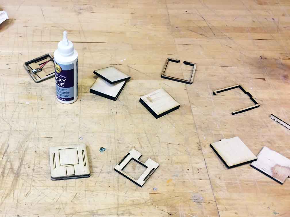
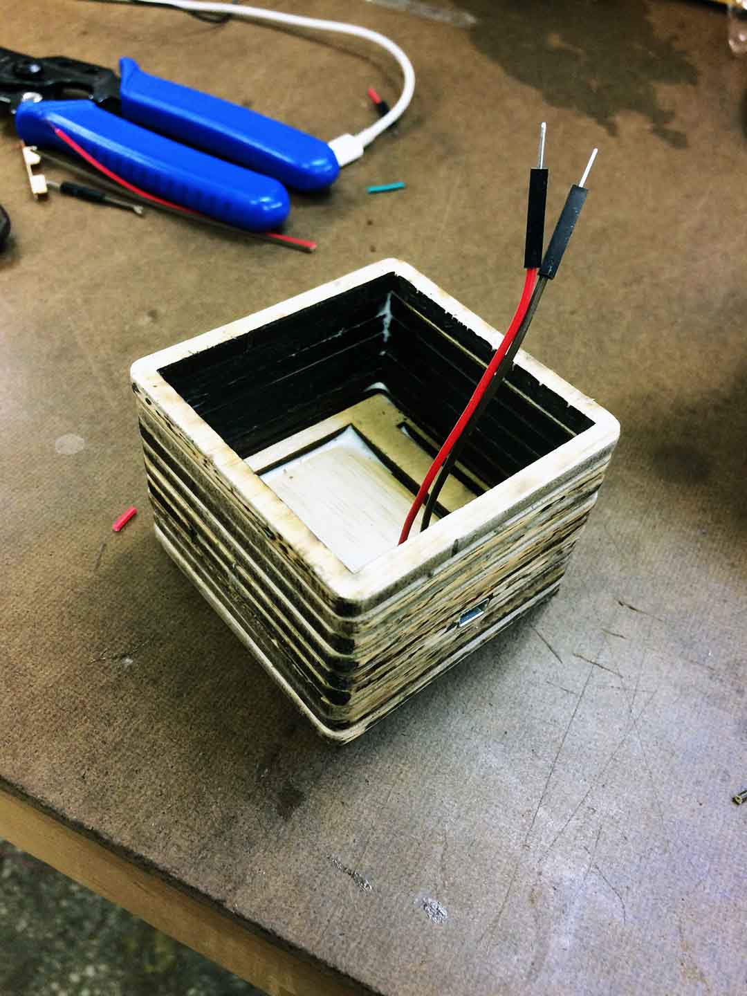
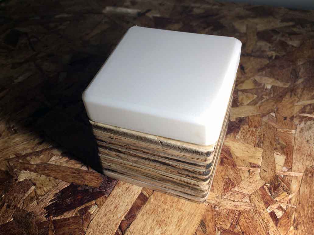
System Integration and packaging
To create the body and the packaging of the lamp I used scraps of Plywood and cut the in the 3D Printer. After that I stacked up and paste them toghether to create a box. Finally, I 3D printed the Lamp shade.