
[05] Electronics Design
Summary
This week I learned the basics of Electronics Design using Autodesk Eagle... a not so friendly design program.
What I did in this session:
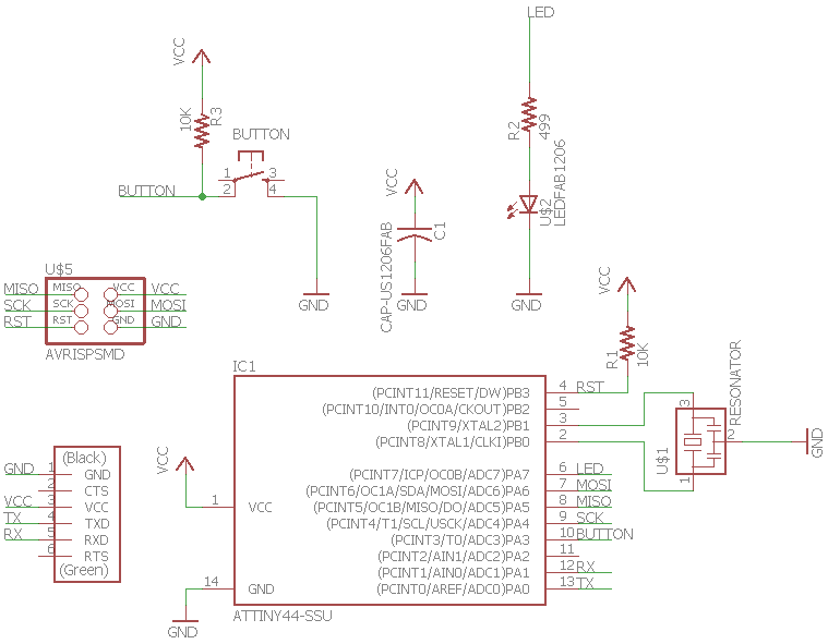
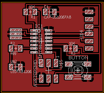
- Design a Circuit Board usign Eagle (squematic and board drawings).
- Practice using the Rolland Mill SRM-20.
- Try to program a board without sucess.
Design in Eagle
Walkthrough
There are a couple of software options to design your circuit. Since I am a novice, I decided to use the Eagle. Given that Autodesk bought Eagle, our TA's knew how to use it and it has online help and documentation easily available, it makes Eagle an excellent option to quickly learn. The Workflow was the following:
- Download Eagle.
- You can download Eagle Software here.
- Download the Lab Library and Design Rules.
- You can download fab.lbr here.
- You can download fab.dru here.
- Read and watch the available tutorials.
- Tutorial 1: Creating Components in Eagle (Almost) Frustration-Free.
- Tutorial 2: PCB Design (This is a great compilation of the best tutorials available).
- Design the Hello Board.
- The parts that you need are: ATtiny44-SSU, 20mhz resonator, 6mm Switch Omrom, AVR ISP SMD header, FTDI SMD header, 10K resistor x 2, 1µF capacitor
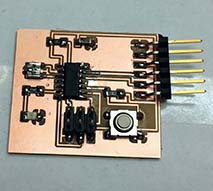
- Mill the board in the SRM-20.
- Solder the components.
- Program the board.
Be careful with the design rules, some of the files have an error and this could create errors on your design. Take some time checking what are the design rules and if they make sense with what you have learned.
If you rename one component or net with the same name in the Schematic, it will connect the elements in the Circuit Board. This tip could help you to mantain a more clear and orderly workspace. Edit>Name and Edit>Label.
Using Options>Assign help you create Hot Keys that makes design more easy.
My main learning takeaways are:
Learn Eagle's workflow
It is important to take your time and read the tutorials. Eagle is a powerful software but if you do not follow the workflow mistakes can be done very easily. I made a mistake of not knowing how to define the width of the traces, and my first Board was a failure.
Select the correct components.
The components in the library can have the same symbol in the schematic but their measures and physical form can be very different in the board design. Be sure to select the correct components, it is very difficult to change all your design if you selected the wrong components.
Export the file with scale.
A recommendation of our TA was to select a file that would mantain the scale of our draw. I use Export>Image>PNG(Monocromatic). Since Lab MODS use PNG, this process is very convenient since its easy to tranfer your design to the Mill.
Milling, Soldering and Programming
For the milling and soldering I followed the steps learned in leason [03] Electronic Production.