[10] Machine Design
Summary
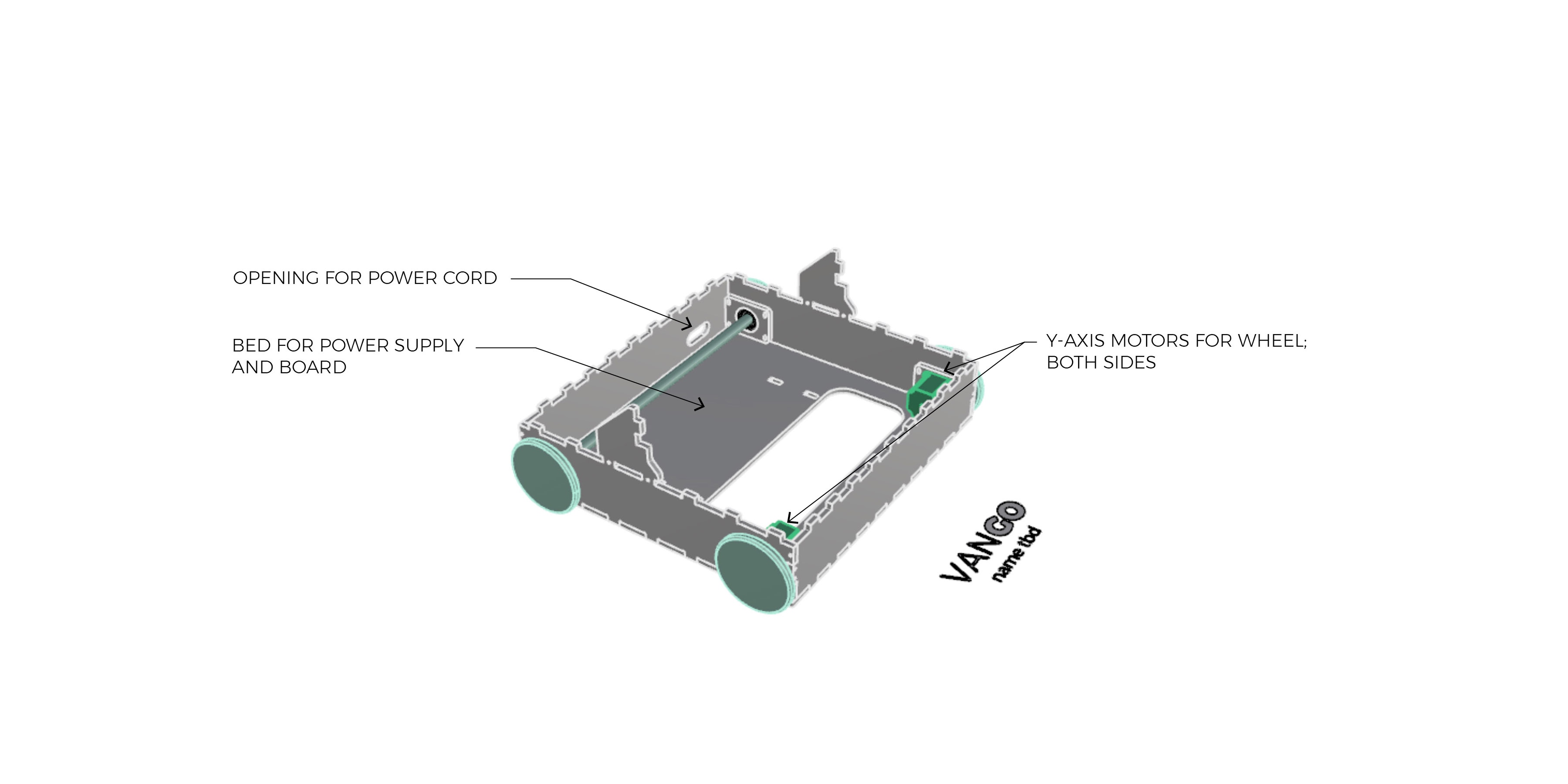
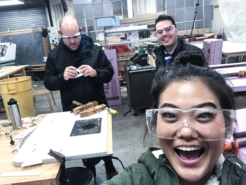
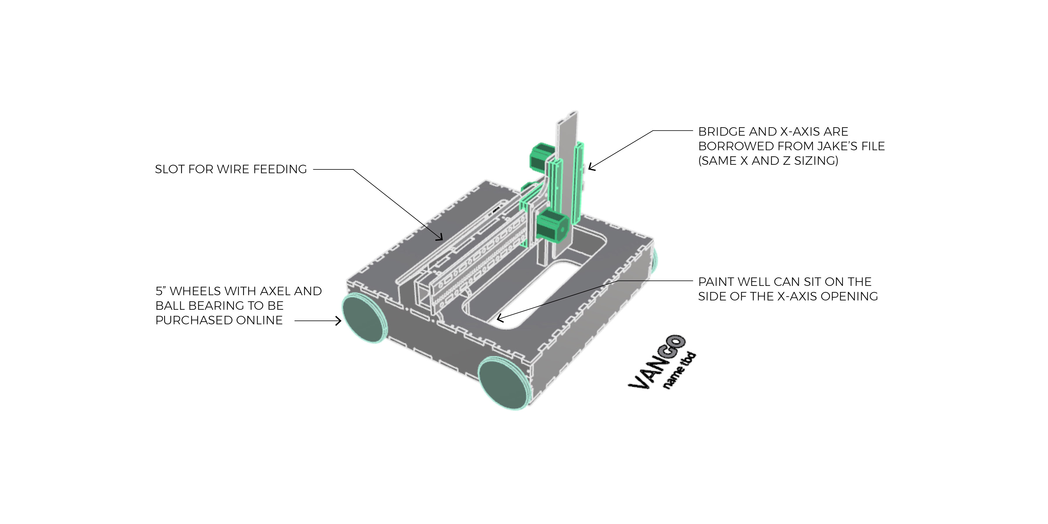
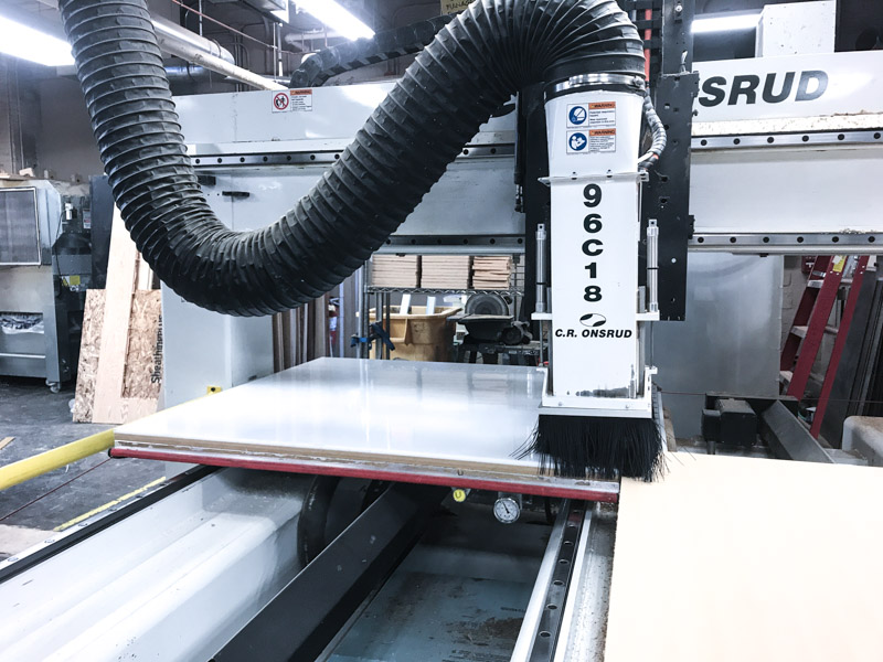
This week was a group assignment and we built a watercolor machine.
The group documentation webpage is: How to build a watercolor machine
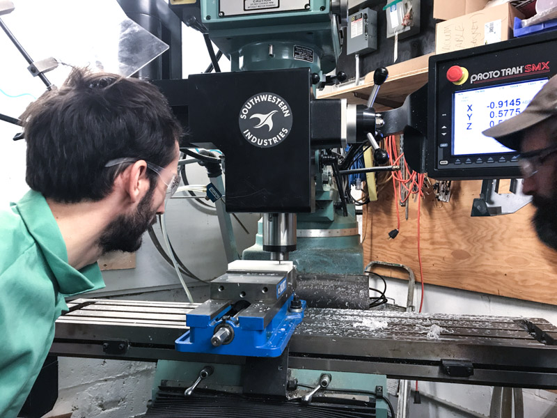
Since I did not know how to use Rhino, my main contribution was to help laying out the pieces in Rhino (learn some Rhino commands in the process) and help in the physical milling process. Here are some of the thing I was involved this week
From design to machining
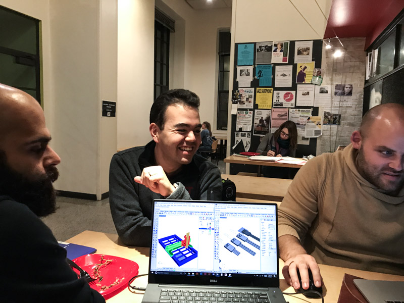
Once we got the design we had to transform the Rhino File that could be use by Mastercam to machine our parts.
The first obvious step was to disassemble the parts of our design and lay them flat on Rhino. To prepare the file in Rhino is important to remember to identify:
- Drilling holes: put a point where you want to drill a hole.
- Outline: Mark the outside line of your model.
- Inside: Mark the inside cuts of your piece.
- Chamfer: we marked the chamfer with a line.
- Pockets: Select all the lines and create a layer to identify your pockets in the drawing. It is important to group pockets by their depth.
- Safe surface: The surface that we do not want the machine to cut into.
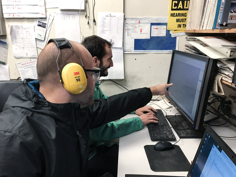
After you get this file, you are ready to bring your design to Mastercam and start programming your machining steps.
Challenges in Mastercam
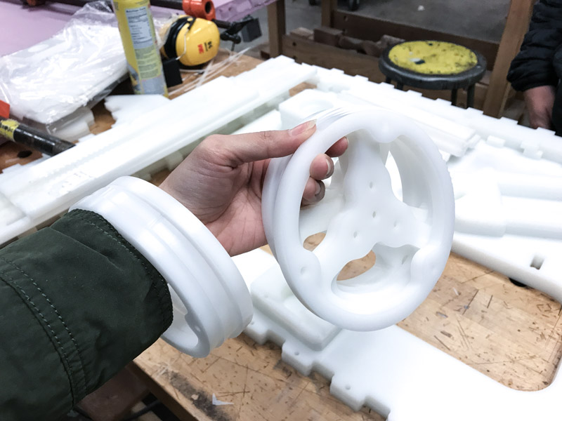
Mastercam was very tricky this week. Since we did not have much material we decided to create a packed design will all the pieces close to each other. This created one of our first problems.
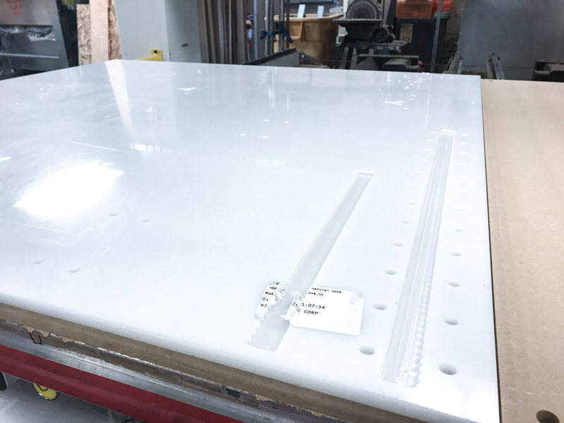
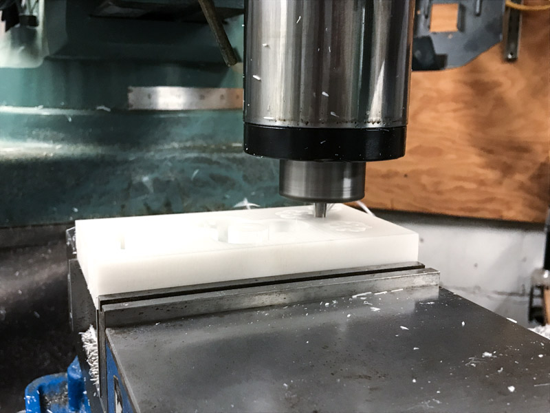
- Pieces jumping out of place: For the first cuts, we program Mastercam so the machine will cut almost to the bottom leaving a thin layer of material that would keep the pieces together and in place. When the machine started to cut the final layer, some of the smaller pieces pop-up out of place and the machine cut some of them, which made them useless. Solution: Thankfully we had enough material to cut again those pieces, but for the second time we decided to leave the thin layer and cut it manually.
- Pockets deep: To be sure that the deep of the pockets was the correct one, we decided to run first the pocket workflow. After that we measured the deep of the pockets, thankfully the cuts were correct and not further adjustments were needed.
- Dealignment of material in the cutting bed: While cutting one of the pieces the milling machine moved the material, this forced us to stop the process and align the material again. To do that from mastercam we selected two points or coordinates of some of the holes that had already being cutted. With that we manage to position the tool in this positions and align the material again. We also had to modify our process to only cut what was missing from our pieces and redo the pieces that the milling process damage.
Other problems that we faced are the following:
Mistakes discovered after cutting
After cutting the pieces two main problems arise:
- The motors used in the design phase where different from the ones ordered: this created a problem since the pieces were designed to fit other type of motors. The assembly team came with a solution to laser cut new pieces that could replace the previously cutted pieces.
- Drilling ⅛ in. holes instead of ¼ in.