[09] Output Devices
Summary
This week we learn to create a circuitboard with an output device.


What I did in this session:
- Design a Circuitboard.
- Use SNB-20 to mill the board.
- Solder components to the board.
- Program the microcontroller and upload the program via a programmer.
- Debug the board.
Design the Circuitboard
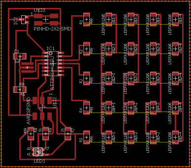
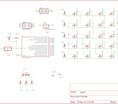
This week I decided to join two board seen in class, the RGB LED Board and the Charliplexing board with 2 layers. The project was too ambicious...
- Design the board in Eagle.
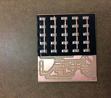
- Miil the board in the SMB-20.
- Solder the components.
- Program the board
- Program the board.
Eagle can be a very frustrating program, follow one of the tutorial we use on week 5.
In this step I had a lot of program to manage to create a communication with the microcontroler. Jonah suggested that because one of my LEDs was connected to the programming PINS this coudl have been causing a problem... and that was the problem. After cutting the connections to the LED, I was able to program my microcontroller.
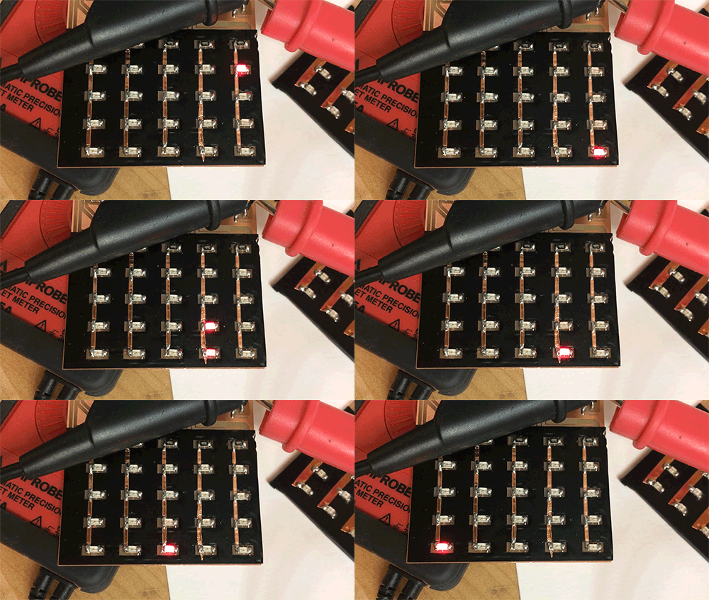
Giving the lack of time i was not able to create my own program and I use the program for the Charliplexing LED project. There I realize that not my LED where working... but the debugging is for another time.
