Introduction
In terms of electronics fabrication, we mainly refer to printed circuit board (PCB) fabrication. In the industry, PCBs are mostly fabricated by chemical etching method. However, this method is very hazaddous to the environment. Therefore, in this class, the PCB will be fabricated in a milling machine. For the soldering, we will use a standard soldering iron to solder surface-mounted electronic components on the board to make an inline programmer.
There are some points to note when milling the PCB:- The endmills are expensive (~15$/ea). Therefore, try not to break them.
- We will use FRI boards, because endmills die quickly with galsses.
- Use the sacrificial layer to protect the endmills.
- Actually, you can make multi-layerred PCBs with Vinyl cutter by using insulating layers between copper layers.
- If you'd like more PCBs, it will make more sense to look for commercial options.
- Make sure all the joints are clean enough to let solder flowing around.
- Use the soldering iron to heat the PCB joint for a long enough time first, and then apply solder wire on the joining point of solder iron and PCB.
- Turn on the electric fan if necessary of let smells and vapors get vent.
- The joints should be shinny and smooth.
- Use a tape to fix the PCB, and then you will not need to worry about the position of PCB.
- DOn't use too much solder, because that doesn't help!
Milling the PCB and Specification Card
The PCB is milled in the Sci center. Here are some results of my week:
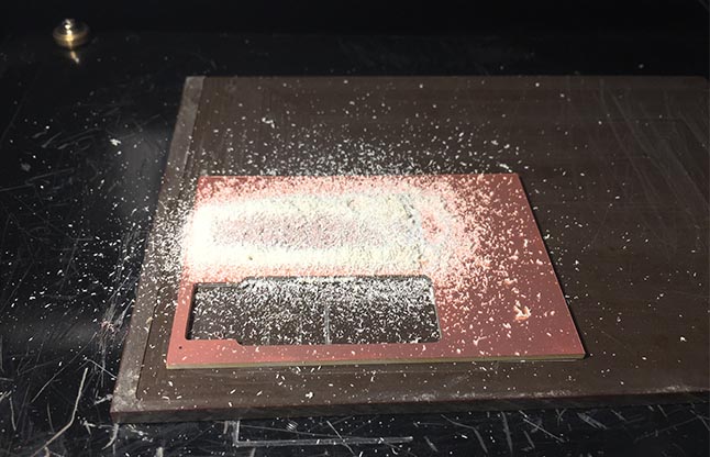
This is the first piece of my PCB. The circuit trace and outer boundary have already finished.
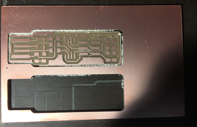
This is the same board, but after all the powders have been vacuumed.
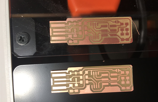
Since there are two different milling machines in the lab, I decided to make two identical boards using two machines. There are two points of making two identical boards. First, I'd like to see whether the quality of two boards from different machines will be different. Second, it will help me master soldering better because I can practice two times.
Notice that there are some copper left in between small traces. I used small knife to remove these copper leftovers with caution. You must be very careful because you can damage the circuit traces very easily.
It turns out the newer machine can produce better traces, which can be seen from the details of this photo. I think this can be explained by difference between the quality of the endmills on these two machines.
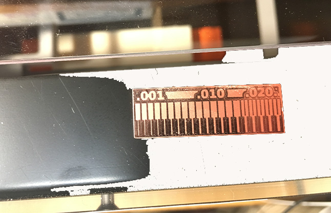
This is the specification card I made for one of the milling machine.
Note that this is an unfinished produce. Here is a lesson I learned: wait longer before hitting the "send to print" button. Otherwise, if you send the pictures before the calculation is finished, the final product will be incomplete like this.
Soldering the Programmer
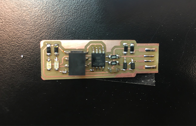
This is the final product of my programmer (since this was before I did all the testing, the bridge was still connected). All the joints are pretty shinny and smooth. The testing after that further confirmed that the soldering was successful.
Testing the Programmer
I did the testing with the help from Dixon. It takes us a while to finish all the setting parts for the board. What we did was simply follow all the instructions written by Brian.
After setting the programmer up, I have tested the functionality of it by writing a program into an empty board.
Basically, we downloaded a package called "hello.RGB.45.c" from the week of "output devices", and then wrote the program into an empty board.
Soldering the Second Board
To practice my soldering skills, I went to the lab to solder the second board on Monday.
The first board took me about 45 min to finish, while the second one only took me about 20 min to finish and even had a better quality than the first one. You know, "practice makes best".
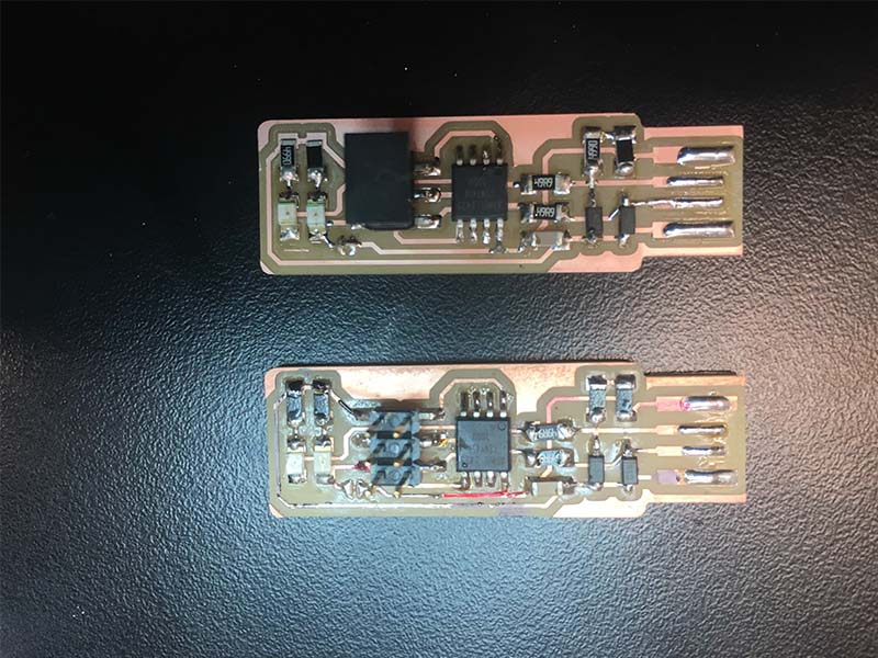
Two boards put together.
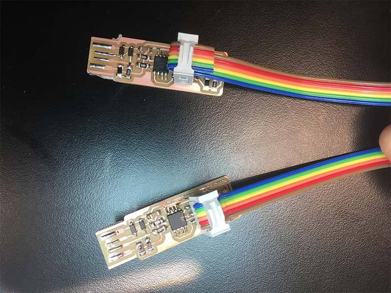
Two boards connected together by a cable.
This time, I used my first board as the programmer to program my second board. After that, I tested the second board using the standard method, and it worked perfectly.