Introduction
This page shows the progress of Richard Liu's final project for the class of "How to make almost anything", 2017.
In my final project, I'm planning to make a three-axis gimbal for my iPhone. Currently, I'd like my gimbal be able to have following functions:
- Stabilizing my phone when walking or running
- Conversion between stick-mounted and bag-mounted
- Heating my phone to make it warm in the winter
- Light-weight and quick assembling and disassembling
- Auto tracking a people/object
- To be continued ...
Progress
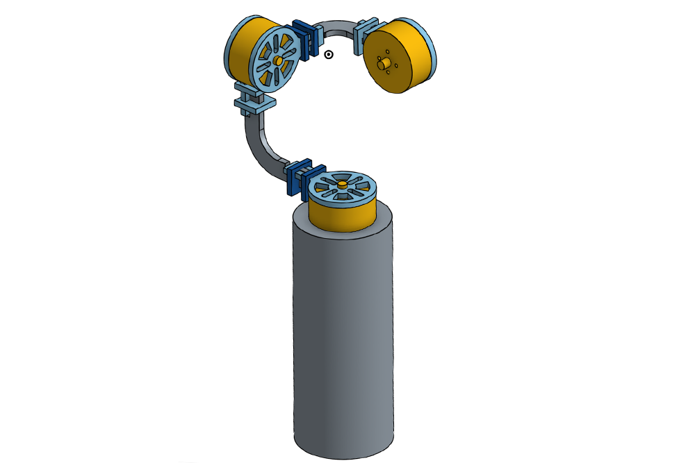
Designing of the Frame
This is the final version for the frame of my gimbal. Basicaly, it will be cut by laser cutter, and assembled in a press-fit manner. Detailed design process is summarized in this link.
The whole frame will be cut out from 3.5 mm Grade 5 Titanium (the hardest titanium alloy).
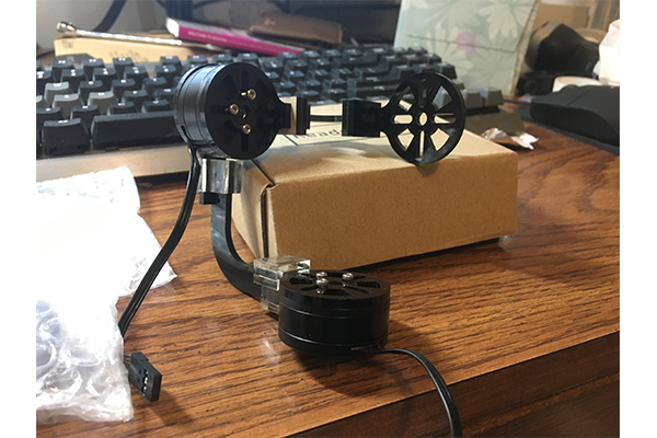
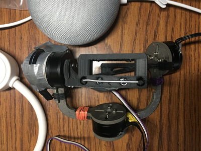
This is a model I cut with laser cutter, with two motors installed:
Designing of the Electronics
Here is the basic control schemes for the gimbal and heater:
- One ATMega328p MCU for overall PID controlling of motors and heater, controlling of LCD display, and control of the main menu. Since the atmega328p only has three timers, it can only generate PWM controls for two BLDC motors.
- One at44A for controlling the third motor.
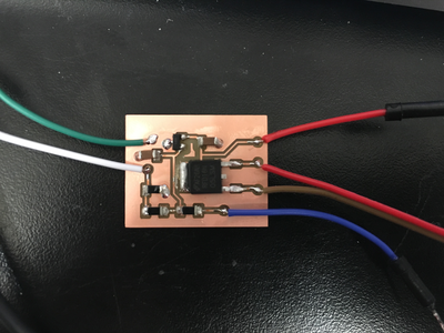
- Heater will be controlled by a seperate at45 MCU. This processor will read temperature from sensor as feedback, and control the MOSFET with PWM signal at the same time.
- Between the main atmega328p board and at44A board, there will be serial communication to send Gyro data.
- There will be three motor drivers (DRV8313) that can amplify the current and thus power the motors.
My control loop is based on what Xiaomeng has done last year. Basically, the atmega328p reads data gyroscope and accelerometer through I2C (Input device week), and then calculate the error array for these two terms. After that, the P, I and D terms will be generated accordingly. Then the MCU will update how many steps (forward or backward) the motor needs to take to get the pre-set equilibrium point.
In my case, I have used a buffer with size 5 to store errors, as shown in the code below:
  errGyroY[4] = errGyroY[3];
  errGyroY[3] = errGyroY[2];
  errGyroY[2] = errGyroY[1];
  errGyroY[1] = errGyroY[0];
  if (GyroY > 32768) {
    errGyroY[0] = GyroY - 65536;
  }
  else{
    errGyroY[0] = GyroY;
  }

  M1 = -((errAcZ[0]+2500)/65536.0*100.0+(errGyroY[0]/65536.0*300.0)+(errAcZ[0]-errAcZ[1])*500.0
  +(errGyroY[0]-errGyroY[1])*500.0);

  stepsM1 = (int) M1;
  ...
The communication between the 1st controller (mega328p) and the 2nd controller (at44) is achieved by modifying Neil's example code with a pin change interrupt:
  void put_data(volatile unsigned char *port, unsigned char pin, uint16_t txchar) {
  ...
  if bit_test(txchar,16)
      set(*port,pin);
   else
      clear(*port,pin);
   bit_delay();
   ...
   }
  void get_data(volatile unsigned char *pins, unsigned char pin, uint16_t *rxbyte) {
  ...
  if pin_test(*pins,pin)
      *rxbyte |= (1 << 15);
   else
      *rxbyte |= (0 << 15);
  ...
  }
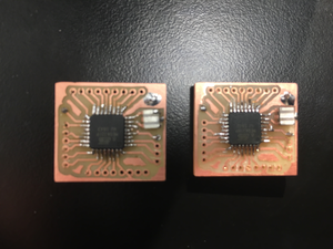
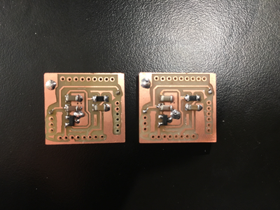
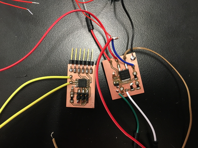
Here are pictures of all the electronics:

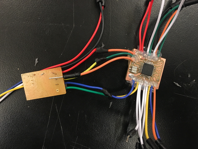
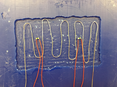
For the heater part, I have used nichrome wires as heating unit to decrease the amount of current needed at a given voltage.
Basically, the at45 will read the value of temperature sensor and convert that into temperature in degree C. Then it will calculate the PID terms from the error array. With the PID terms determined, the setpoint will be computed and the PWM duty will be assigned accordingly.
      chrL = ADCL;
      chrH = ADCH;
      rawData = (chrH << 8)|(chrL);
      if (rawData > 511) rawData -= 1024;
      V = 2.5 - rawData*5.0/(20.0*512.0);
      R = 10000.0/((5.0/V)-1.0);
      T = 1.0/(log(R/R25)/B+(1/(25.0+273.15))) - 273.15;
      error[4]=error[3];
      error[3]=error[2];
      error[2]=error[1];
      error[1]=error[0];
      error[0]=T - 25.0;

      setPoint = -(error[0]*50.0+(error[4]+error[3]+error[2]+error[1]
      +error[0])*0.1+(error[0]-error[1])*20);

      if (setPoint>128 )setPoint=128;
      if (setPoint<-128) setPoint=-128;
      output = (int) (256-setPoint)/2;
      OCR0A = output;
      _delay_ms(10);
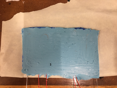
Here are some pictures of the heater part:
Results of my final project
Unfortunately, I didn't get my final project work as expected.
For the gimbal part, it took me very long time in the beginning trying to get the basic driver board and control loop to work, and I finally realized the importance of balancing the frame carefully. If the center of mass of gimbal was not at the balanced point, the gimbal would simply not work, even if it's running at 12V and pretty large current (300mA for each motor).
Here is the picture of the gimbal before and after balancing:
After that, I successfully got two axes work as expected. When I was trying to get the third motor connected in the last minute, the motor driver failed. So I got a lesson that sometimes it's not always better to use a higher performance component. Most of time, reliability and production difficulty matters more.
For the heater part, I first tested the temperature sensor, and it works properly. Then I tested the functionality of the MOSFET and heating unit. It turns out the MOSFET heats much faster than the heating unit, which kind of makes me want to use the MOSFET as heating unit instead of nichrome wire. I think the problem is caused by the too small resistance of the nichrome wire.