Introduction
In this week, we have mainly learned how to design our own PCB in Eagle.
Before actually starting designing and machining my first board, I have taken several tutorials on Eagle and microcontroller online, and here are the links for them:
- An Eagle tutorial for freshman provided by SparkFun. It consists of three parts, How to install and run Eagle, Schematic in Eagle, and Board layout in Eagle.
- There are many tutorials for microcontrollers on Youtube, and you can find a good one very easily.
- Learn how to use a software to desin the PCB.
- Reproduce the "echo hello world" board, and machine it out followed by soldering all the components.
- Optionally program the board and test it.
Learning Eagle
Before working on the actual board I'm gonna to machine for this week, I have follwed the tutorial on how to use Eagle from SparkFun -- building an Arduino board.
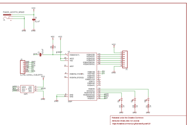
This is the schematic of the board.
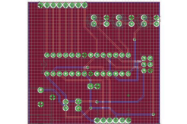
This is the layout of the board. This one is different from our weekly assignmnet in the way that this is a double-sided board.
After I finish the tutorials, I have mastered the basc procedures to design a board in Eagle. Besides that, there are also many good tips in the tutorial regarding how to design efficiently, and how to check your error. I'd also to mention that there are many interesting eaxmple boards helping your understand microcontrollers and Eagle. Therefore, I hignly recommend this set of tutorials if you're new to Eagle.
Reproducing and modification of the "echo hello world" board
This week's assignment is not just simply reproducing the existing board, since there are several free pins on the microcontroller, I need to make use of those free pins to add some functions to the board.
I decided to add a thermal resistor on one of the free pins which will be set as an input pin, and a LED connecting to another free pin as an indicator of temperature. Basically, I will connect Vcc to thermal resistor, and then connected to ground through a fixed-value resistor. One free pin will be in parallel to the fixed-value resistor to read out voltage divided by it. Then the microcontroller will set the amount of voltage to LED accordingly.
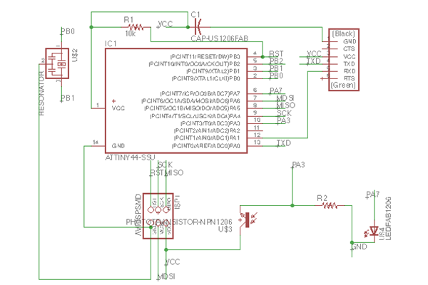
This is the schematic of my version of "echo hello" board. The thermal resistor and LED are placed in the lower right corner in the schematic.
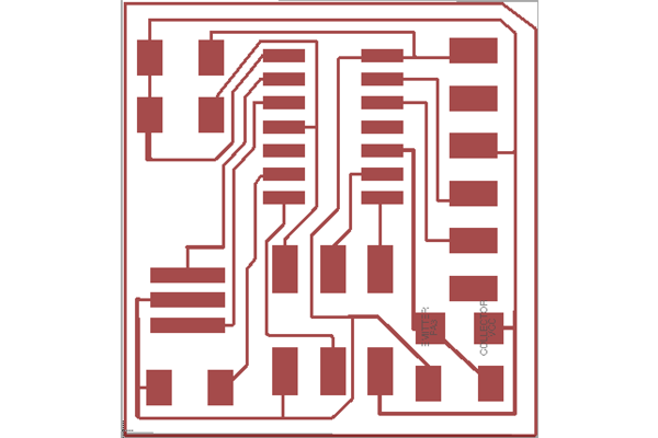
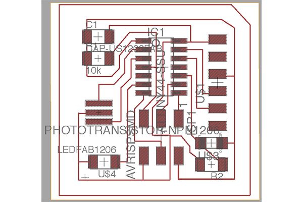
This is the final version of my design. Actually, before this one, I have made several bad designs.
Maching and soldering the board
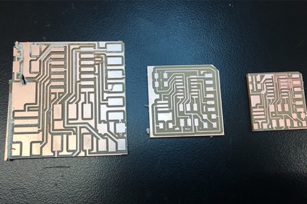
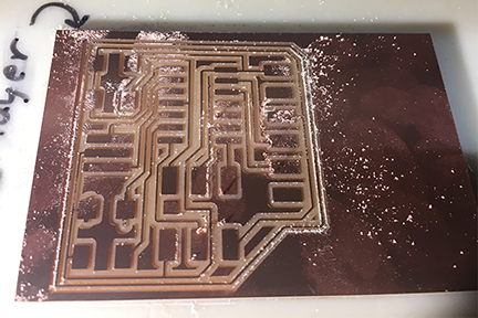
This picture shows all three boards I have made this week. For the left one, it has two problems. The first one is because of some weird bug in the Eagle software on Mac. When I save the layout in the format of png, the actual resolution is doubled. The second problem is instable board during cutting. Because I have used not enough tape under the board, it came off from the bed, which totally destroyed the circuit.
On the right, there is another failure. Also two problems exist in thie board. First, some of the wires in this board are not separated by enough distance, which causes them cross-link with each other. Second, because I used too much tape under the board, there were some areas with overlapping tape, and thus made the board not flat during cutting. As a result, there are some parts not cutting deeply enough.
In the middle, it's a good one.
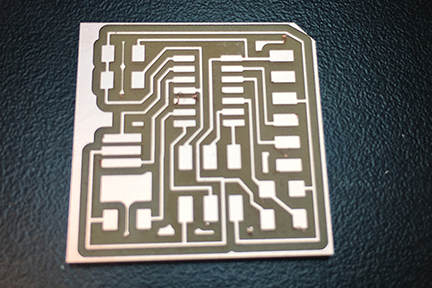
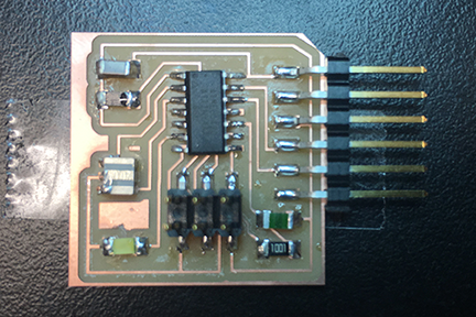
This is the finished board with all components soldered. Unfortunately, I don't have enough time to finish the programming and testing.
Circuit for a heartbeat monitor wrist band
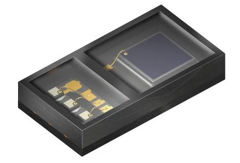
As a practice for electronics design and microcontroller, I want to design a circuit for monitoring my heartbeat and send it to my phone through bluetooth in real time.
Here are the features I'd like to add for thie device:
- Readout the heartbeat in real time, which requires a microcontroller with op-amp inside
- Send out the heartbeat rate through bluetooth, and thus the microcontroller should be able to communicate with bluetooth module
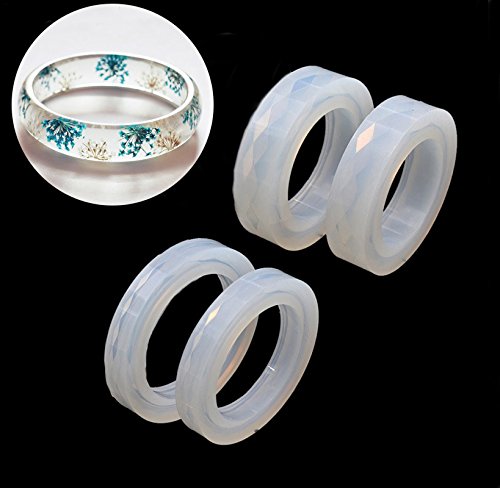
- The circuit should be able to be cut by a Vinyl cutter, such that the circuit can be placed inside the ruber band shown above