Electronic Part Design
Drive the motor
To select a proper driver for my motor, I need to know the specifications needed in my project, like current for each motor, voltage, and power supply. For the power supply, I will use a normal 5V power bank. For the current required by each motor, I will just use the specifications for "DJI OSMO Mobile" as a reference. DJI mobile has very similar functions to what I'm going to build in my final project. For the gimbal part, it uses a 11.1V battery, and the total power consumed by the gimbal is 2.5W for three motors. Therefore, I think in my case, I will order several different kinds of half-bridge BLDC motor drivers, and then test which one satisfies my requirements best.
DRV
The first driver I tried was
The BLDC motor can spin, as shown in the video. However, there is no way that I can control the spinning of the motor smoothly.
Finally, I realized that this driver was designed for driving BLDC motors for CPU fans. Therefore, I decided to use the DRV8313 instead.
DRV8313 Driver
Here are the specifications for this driver:
- 8V minimum working voltage
- Sleeping mode
- Fault detection and reset available
Here is the design for the driver board:

And here are the C codes for generating PWM controlling signals:
Python codes for calculating three sin wave signals seperated by 120 degrees each:
%pylab inline
x = linspace(0,2*pi,256)
y1 = array([int(floor(k)) for k in 128+128*sin(x)])
y2 = array([int(floor(k)) for k in 128+128*sin(x+2*pi/3.)])
y3 = array([int(floor(k)) for k in 128+128*sin(x+4*pi/3.)])

savetxt('y1.txt',y1,fmt='%d',newline=',')
savetxt('y2.txt',y2,fmt='%d',newline=',')
savetxt('y3.txt',y3,fmt='%d',newline=',')
During the testing of this driver, I have encountered a very frustrating problem. As shown in the video below, the motor first moves smoothly, and then it jumps back abruptly.
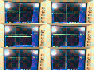
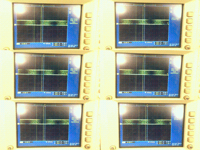
The PWM signal output from controller is measured by oscilloscope and shown below. The abrupt jump is caused by the sudden change in the PWM signal (the flat area in the middle).


It takes me several days to debug this problem. After changing the C codes and driver board several times, I finally figured out that it's problem with the sin waveform array in the codes.
To be precise, I have used the np.round() in the python code previously, which generates integer in the full range from 0 to 256. However, in C, the 8 bit integer only changes from 0 to 255. Therefore, the number 256 will never be matched in timer. After I change the code to np.floor(), the motor spins smoothly and beautifully!


Control three motors at the same time
There are three timers to generate PWM in my ATMega328p controller, which means I can only control two motors at the same time if I'd like to use timers to generate PWM signal. Therefore, I need to split the controlling task to seperate smaller MCUs.