Introduction
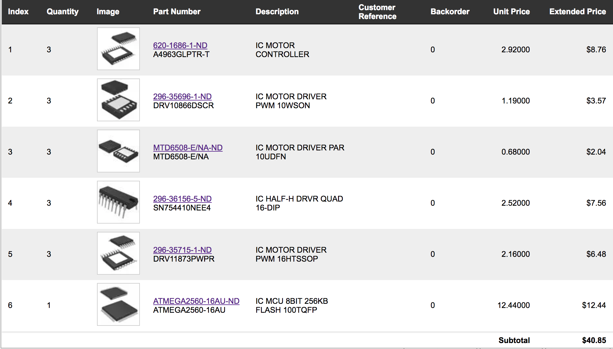
To select a proper driver for my motor, I need to know the specifications needed in my project, like current for each motor, voltage, and power supply. For the power supply, I will use a normal 5V power bank. For the current required by each motor, I will just use the specifications for "DJI OSMO Mobile" as a reference. DJI mobile has very similar functions to what I'm going to build in my final project. For the gimbal part, it uses a 11.1V battery, and the total power consumed by the gimbal is 2.5W for three motors. Therefore, I think in my case, I will order several different kinds of half-bridge BLDC motor drivers, and then test which one satisfies my requirements best.
Here is a list of different drivers I have ordered for the test:
Controller for output devices
Before actually testing my output devices, I think it's time to make a controller board now, instead of making a new board every time I got a new task.
Here are my expectations for the controller boards:
- It should contain enough input/output pins for my purposes (I potentially will have 3 BLDC motor, a 6-axes accelerometer, a temperature sensor and a heater)
- It should contain an ISP header for me to convinently upload programs onto the board
- It should be able to communicate with computer through a FTDI cable, such that I can control the board and debug it easily on a computer
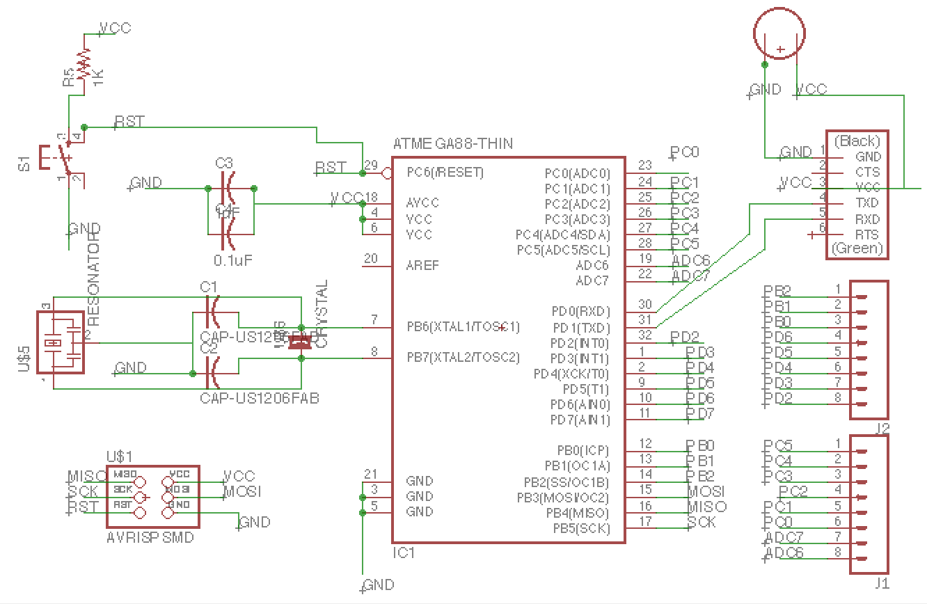
Take all above concerns into account, I have designed a double-side controlelr board using ATmega328p based on the "Xmega hello world" board from embedded programming week.
Here are the eagle scheme for the board:
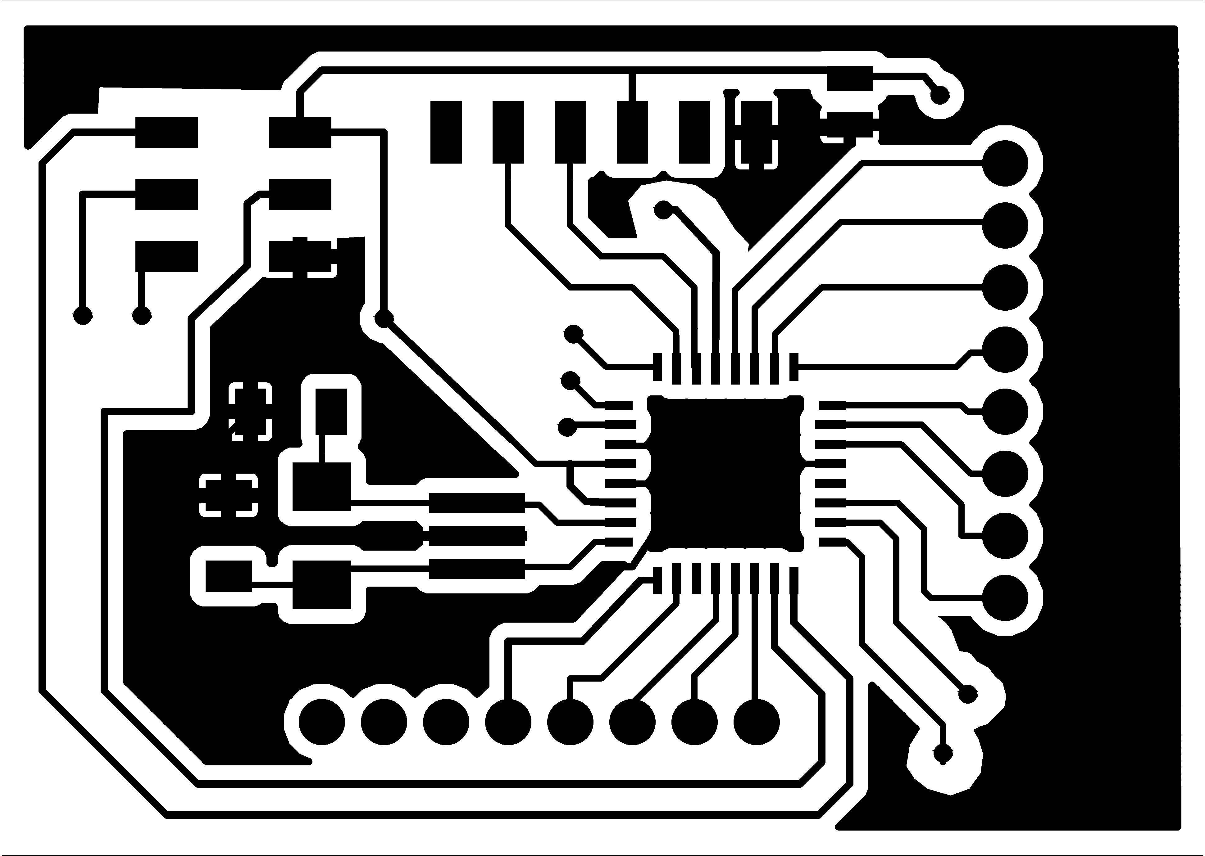
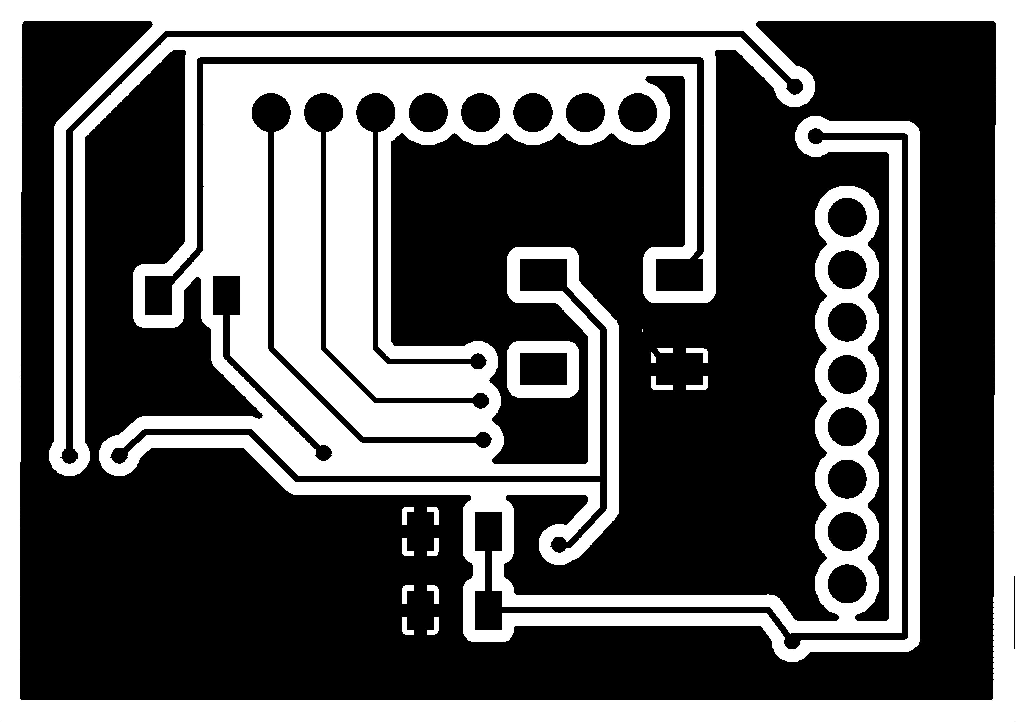
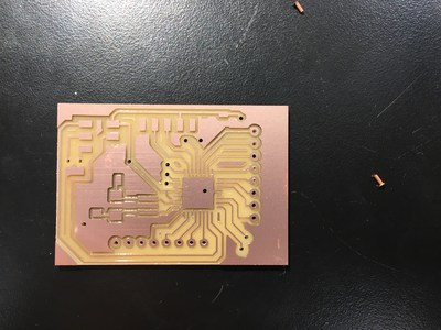
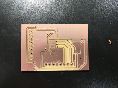
Then I generated three picture files as follows, labelled as mega_fron, mega_back, vias.

In making this board, I have met several problems:
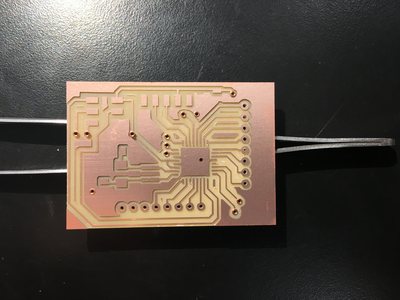
- It's hard to match top layer and bottom layer exactly. The way I solve this problem is to mill the first layer with 1/64" end mill, and then vias and board boundary with 1/32" end mill. After that, I took the board out of the piece, and flip it vertically. In this way, the top and bottom layer can match perfectly.
- Another problem is that it's not easy to fix the board on bed after flipping it, partly because the bottom (previously the top layer) has no longer been flat, and partly because it's hard to use tape on a small surface. This problem was solved by using tapes on the top of boards.
This is the picture of finished boards:
Then here is the board after I have soldered all the components:
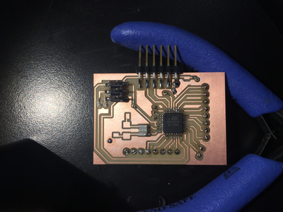
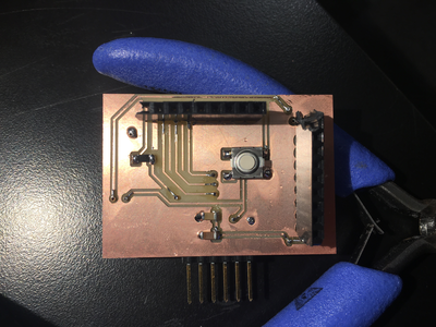
In the center of bottom layer, there is a reset button that can reset the program when pressed. Unfortunately, the motor drivers that I ordered from DigiKey cannot arrive until Thursday. Therefore, I can only play with other output devices (I will update BLDC motor drivers in the final project page instead.)
Output Devices
I have tried controlling of RGB LED this week. I will not post my code for this part because it's very similar to the example code provided on class page.
Computer controlled output and interrupt
After successfully output RGB LED, I decided to try controlling my board with computer.
First of all, I tried to repeat the "echo hello world" program learned in embedded programming week. After that, I tried to add simple timer interrupt in my LED functions to get myself familiar to how interrupt actually works.
Here are the code for simple timer interrupt:
#include <avr/io.h>
#include <util/delay.h>
#include <avr/interrupt.h>
#include <avr/pgmspace.h>

#define output(directions,pin) (directions |= pin) // set port direction for output
#define set(port,pin) (port |= pin) // set port pin
#define clear(port,pin) (port &= (~pin)) // clear port pin

//Output pins for RGB LED control
#define led_port PORTB
#define led_direction DDRB
#define red (1 << PB0)
#define green (1 << PB1)
#define blue (1 << PB2)

int main(void) {
   CLKPR = (1 << CLKPCE);// set clock divider to /1
   CLKPR = (0 << CLKPS3) | (0 << CLKPS2) | (0 << CLKPS1) | (0 << CLKPS0);

   output(led_direction,red);
   output(led_direction,green);
   output(led_direction,blue);

   TCCR0A |= (1 << WGM01); // Set the Timer Mode to CTC
   OCR0A = 0xC34; //3124 in hex, equivalent to 160 ms of
   TIMSK0 |= (1 << OCIE0A); //Set interrupt on compare match
   TCCR0B |= (1 << CS02) | (1 << CS00); //Set prescale to 1024
   sei(); // enable interrupt
   // main loop
   while (1) {
      // wait for compare match
      ;
   }
}

ISR (TIMER0_COMPA_vect) {
   //
   // timer match interrupt handler
   //
   set(led_port,blue);
   _delay_ms(1000);
   set(led_port,green);
   _delay_ms(1000);
   set(led_port,red);
   _delay_ms(1000);
   clear(led_port,red);
   clear(led_port,green);
   clear(led_port,blue);
   _delay_ms(1000);
}
Based on this simple program, I can modify the "echo hello" program into a computer-controlled RGB LED blink program (through this simple program, I found that it's not easy to do string or char operation on a avr processor, probably because it will require extra space to load char libraries into processor. The correct way is to do char matching directly):
By saying that, I mean the operation "unsigned int led = chr - '0'" doesn't work on the processor. Instead, I need to compare it manually.
I have also tested the reset pin, and it works just as designed!
...
TCCR0A |= (1 << WGM01); // Set the Timer Mode to CTC
   OCR0A = 0xC34; //3124 in hex, equivalent to 160 ms of
   //OCR0A = 0x1A8;
   TIMSK0 |= (1 << OCIE0A); //Set interrupt on compare match
   TCCR0B |= (1 << CS02) | (1 << CS00); //Set prescale to 1024
   sei(); // enable interrupt
   while (1) {
      //
      get_char(&serial_pins, serial_pin_in, &chr);
      if (chr == '0') {
         led = 0;
      }
      else if (chr == '1') {
         led = 1;
      }
      else if (chr == '2') {
         led = 2;
      }
   }
}
ISR(TIMER0_COMPA_vect) {
   //
   // timer match interrupt handler
   //
   if (led == 0) {
      clear(led_port, green);
      clear(led_port, blue);
      set(led_port, red);
   }
   else if (led == 1) {
      clear(led_port, red);
      clear(led_port, blue);
      set(led_port, green);
   }
   else if (led == 2) {
      clear(led_port, green);
      clear(led_port, red);
      set(led_port, blue);
   }
}