Week 1 - Introduction and Computer-Aided Design
This week we were given an introduction to the course requirements and expectations, as well as introduced to some key CAD concepts and software
About My Final Project
For my final project, I have decided to make a crude photolithography exposure tool. Photolithography is the most important and critically controlled step in semiconductor manufacturing as it is the process that
determines the actual size of the features that get created. I have used many direct write (serially draws a pattern like 3D printing) and stepper (projects an already existing pattern) exposure tools. They each
have their own benefits and drawbacks, but when it comes to passion projects these tools are extremely cost prohibitive and require a lot of support steps. I have some projects in mind that I would love to do
with the use of photolithography, and I wouldn't even need a top-of-the-line high-resolution tightly-controlled machine. I could very likely get by with a very simple near-contact exposure tool and crude printed
masks on transparent film. As such, I have decided to make the photolithography exposure tool I would need to be able to do my own basic photolithography processing!
- Plan and sketch a final potential project
- Model a possible final project
- Compress images and videos
- Post a description with design files on our website
Planning and Sketching a Final Project
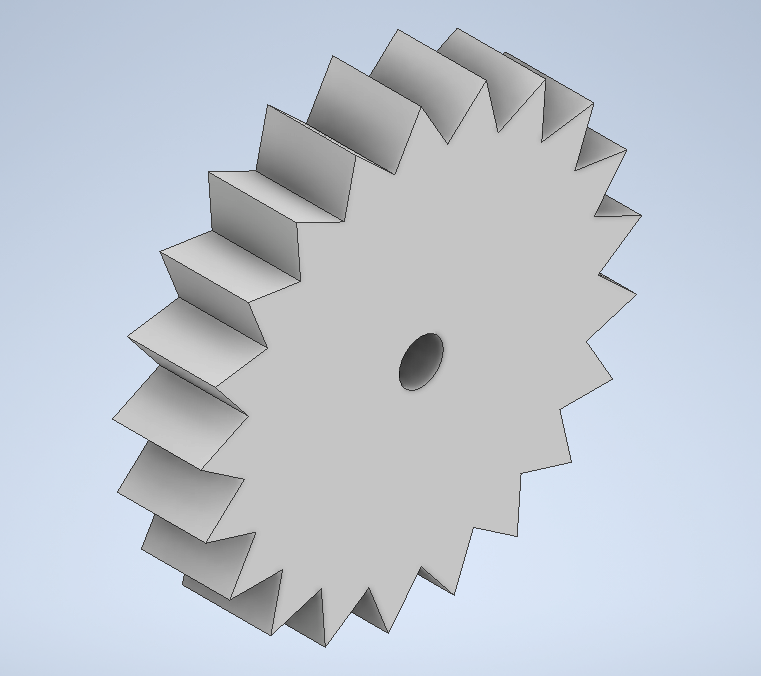
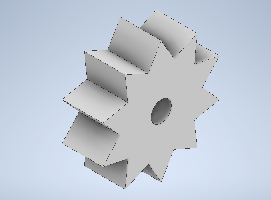
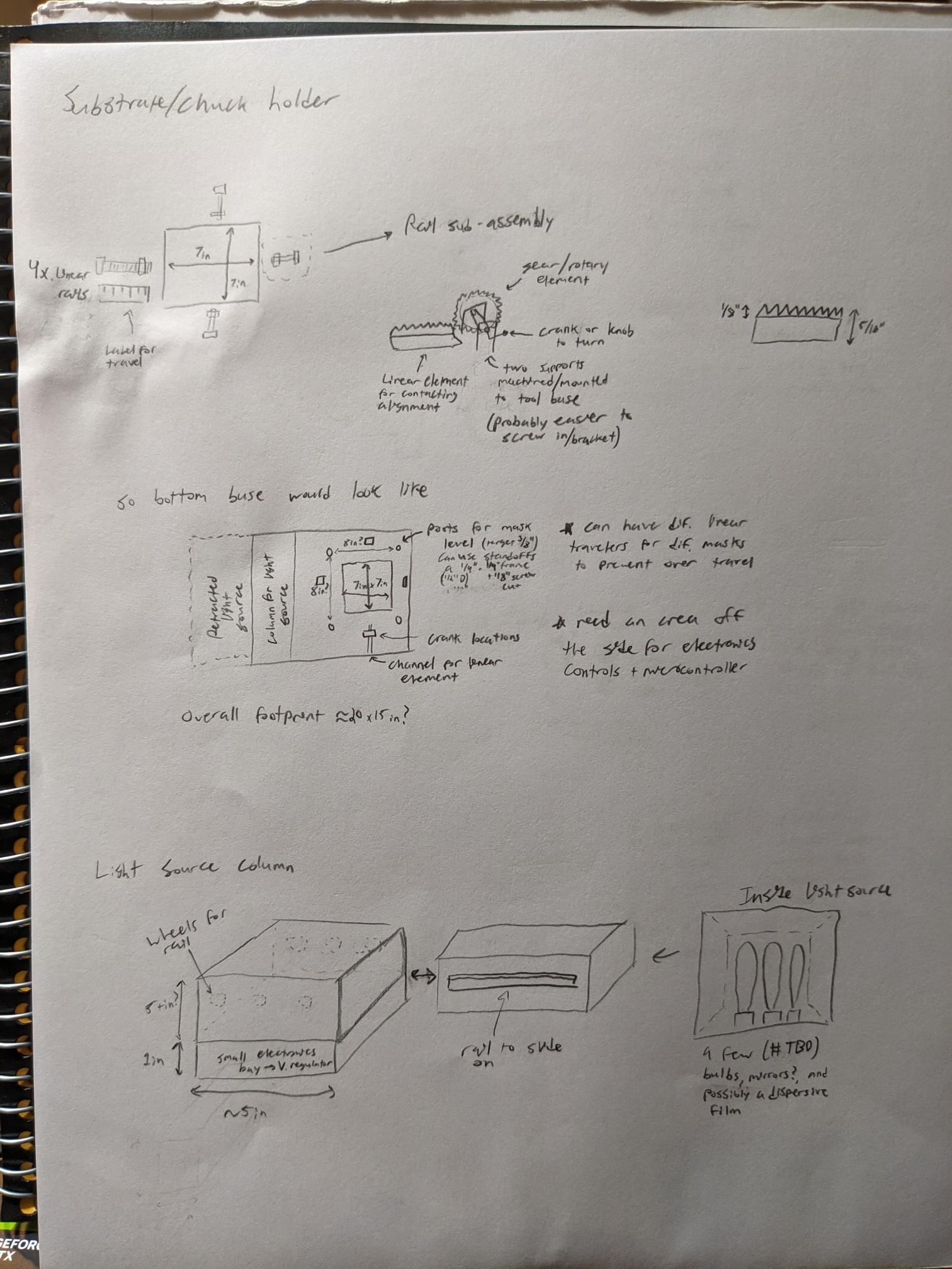
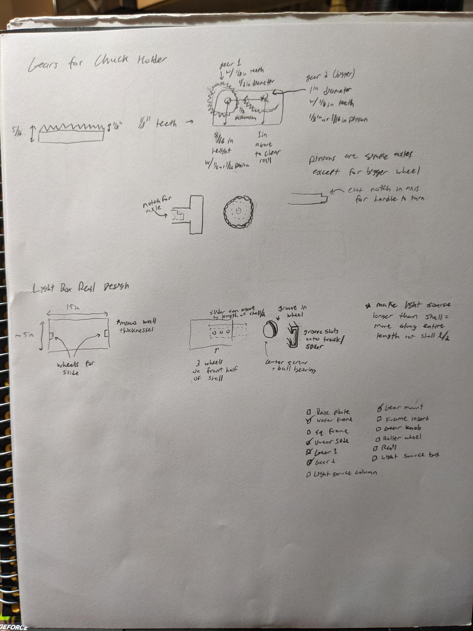
The below images are of the initial sketches that I created when starting to think about the different components that would be needed for this project. I initially wrote out some of the main characteristics for this project, namely the compatibility with printed masks and the ability to take multiple different substrates. Following the initial sketch, I came up with some ideas for sub-components that are needed like the chuck frame and the light source column. As I was drawing these sections, I was able to further break out how I wanted to design individual components to accomplish the goal of the sub-assembly. A prime example of this would be the gears and linear toothed rail slide. Initially, I planned on using a set screw for the alignment. But after trying to figure out how to translate the rotational motion into a different direction I realized that I could keep the rotation in the same plane. The result is the sketch of what I called the linear element (because I have no idea if there is an actual technical term for it) that consists of a gear that will turn and move the slide based on the interlocking teeth. The last things to point out are some initial ideas for how to slide the light box out of its housing after the substrate has been aligned, and a checklist I came up with for parts that I need to CAD.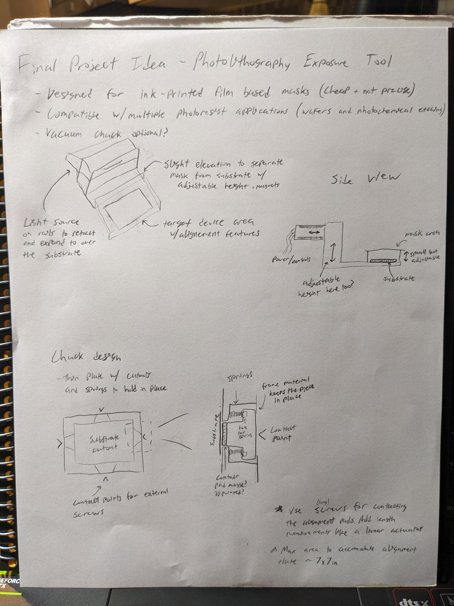
Modeling Final Project
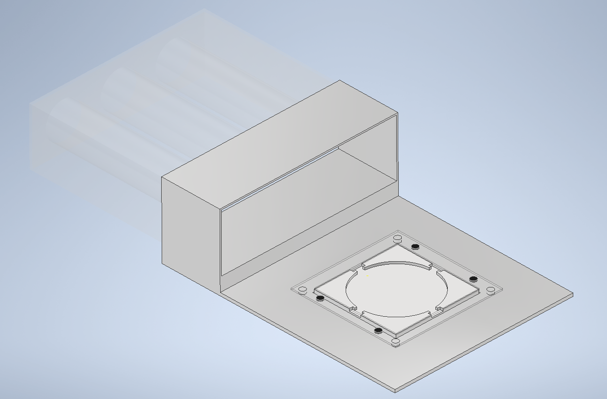
Once I had some initial sketches of what I wanted to do, I created a very rudimentary CAD model with approximate dimensions. Not all the components are included, for example there is no gear system in this model. But this helped me get an idea of the dimensions and spacing I would be working with when I actually start doing the first round of real CAD designs. I was also able to use this model to play around with the rendering and texturing capabilities, and I was even able to make a short video of how the light box would extend out from its housing. I did also start working on the actual CAD models too, and I made some pretty good progress on a couple of them. One of the sketches above has a checklist, that at the time of taking the picture had 5/13 components completed. Screenshots of completed components are also included in this page but further details are discussed in the final project tab of my site.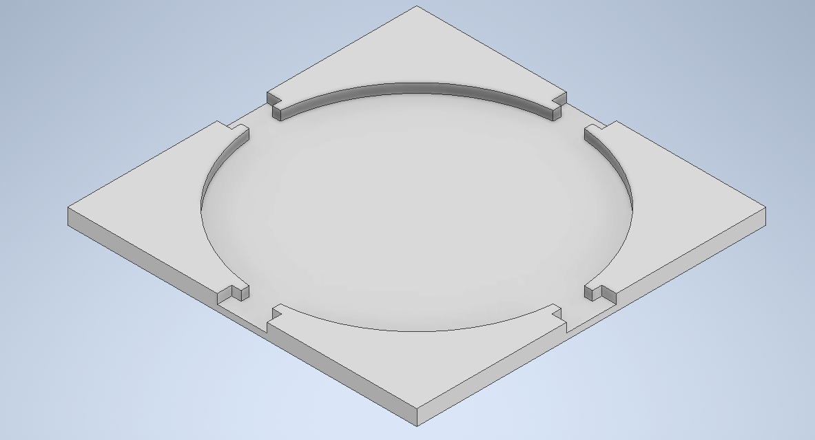
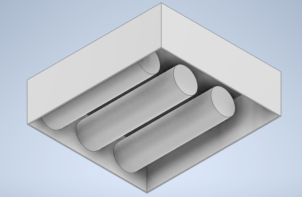
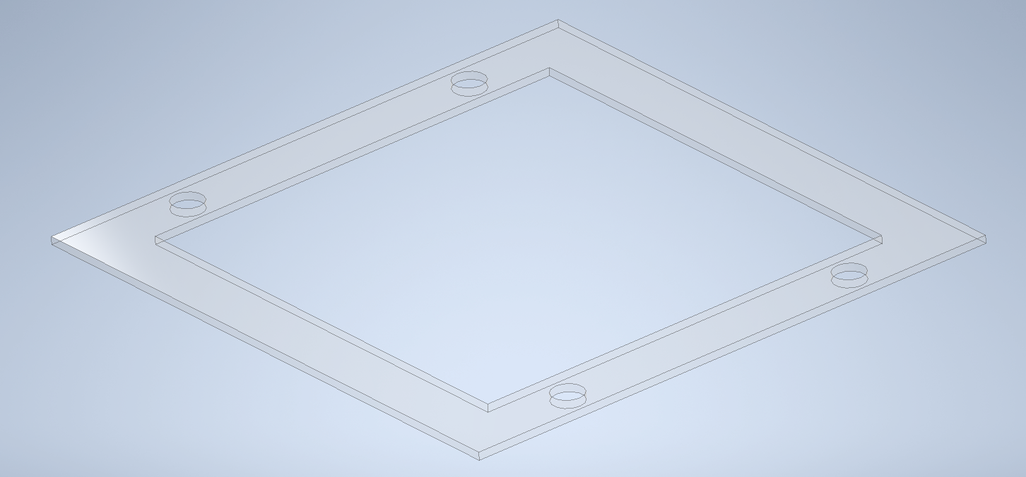
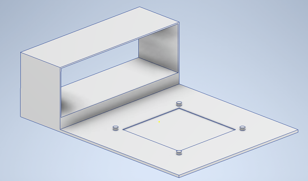
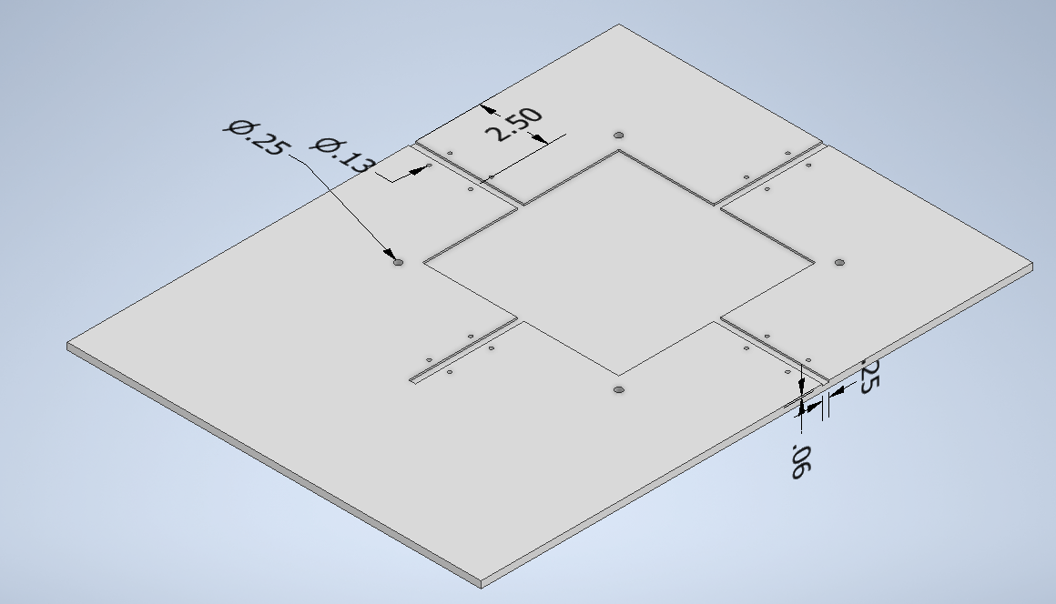
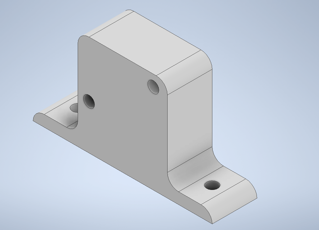
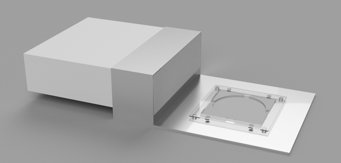
In the above images, the top left picture is of an alignment chuck for a 6in wafer. The central pocket is slightly larger to allow the alignment pads some room to come in from the cutouts on the sides to actually hold the substrate in place. The top right image is a crude drawing of the light box, initially I was thinking about putting bulbs in but now I am going to make my own board with surface mount white or UV LEDs pending some experimentation. The bottom left is the raised frame that will have magnets inserted into the holes to hold the printed mask in place above the substrate, this piece is transparent because I am planning on making it out of a plastic/acrylic material and was playing with material features. And finally, the bottom right is the main body/plate that everything will be attached to. Ultimately the light column will be made separately and attached mechanically, but for simplicity I modeled it all together. This component is also currently made from aluminum in the CAD, but I am thinking that I will likely make it out of acrylic if possible. There will be some CNC cuts required for this piece, and I am not sure if CNCs are tuned for plastic. When combined, these components create the assembly seen below. I then imported the assembly into Fusion 360 to handle the rendering and animation.
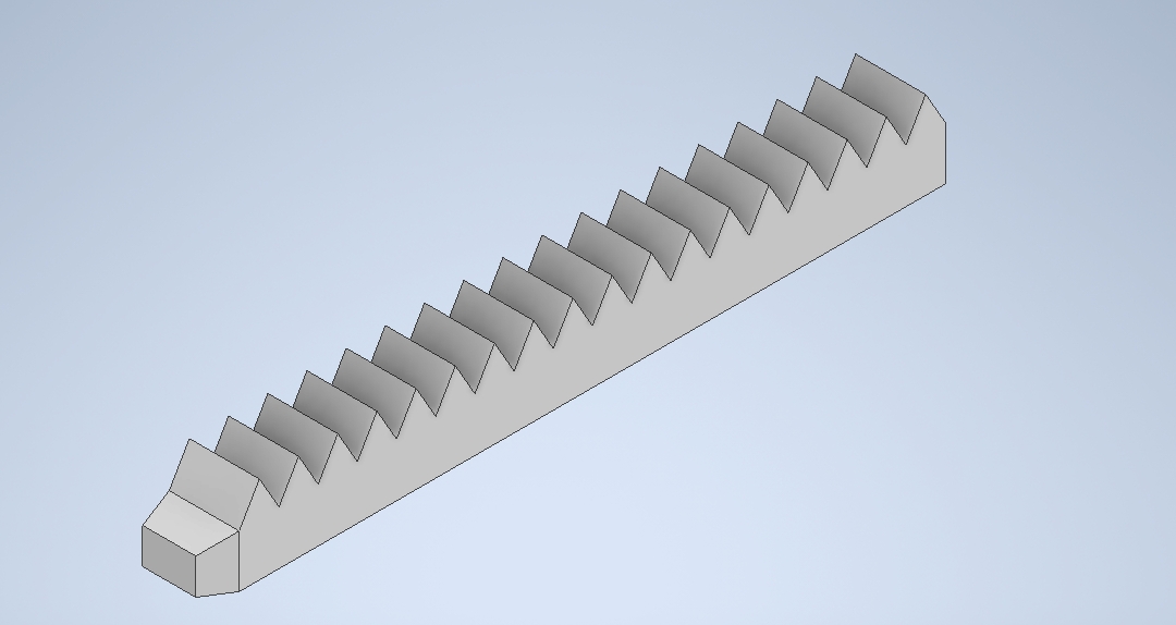
As referenced earlier on this week's page, I did create a few CAD parts that are closer to what a final design might look like. These parts are the base plate, the 6in wafer frame, and the gear assembly (minus the knob). Even now though there are some additional changes/more work I will need to make to the base plate before the first pass is done, so the uploads to this page will mark what progress has been made up to this point. Finalized designs will be included and discussed further on the Final Project page.