Week 9 - Output Devices
As a corollary to last week, this week we covered output devices! There was a good chance we had already been playing with some of these components to finish other assignments, but the intent was that we would become more advanced in our implementation of them. Devices we covered this week include speakers, screens/displays, and an equally large variety of both LEDs and motors.
Assignments:- As a group measure the power consumption of an output device
- Add an output device to a microcontroller board we designed and program it to do something
Measure an Output Device
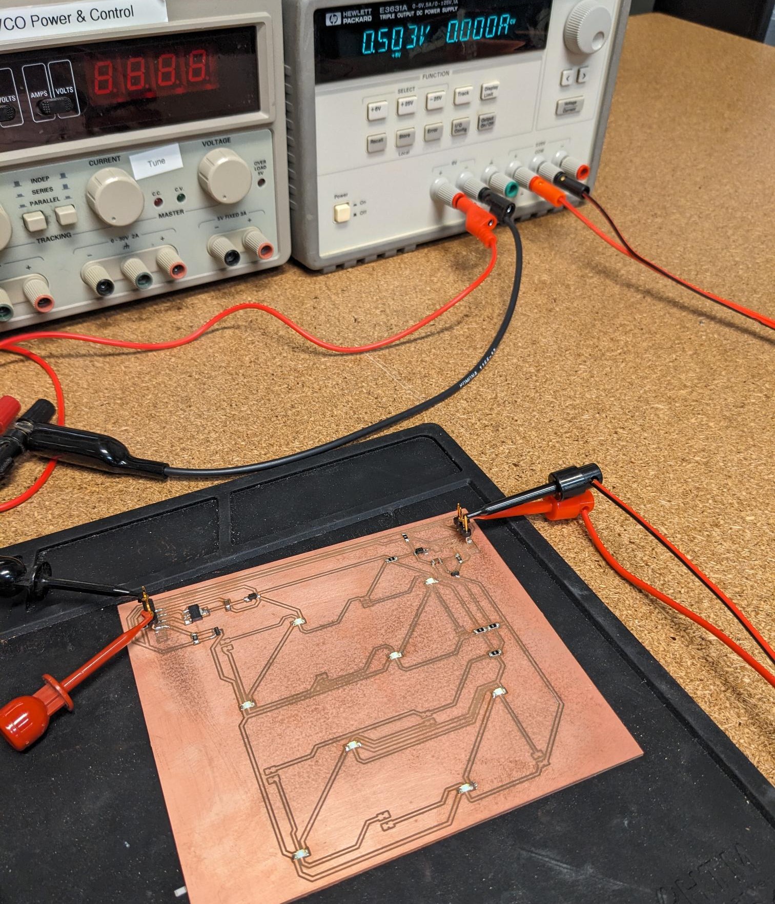
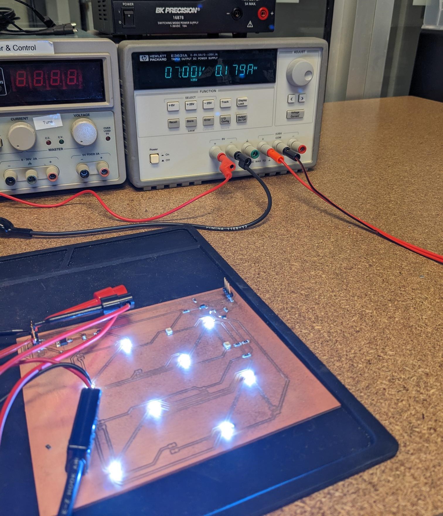
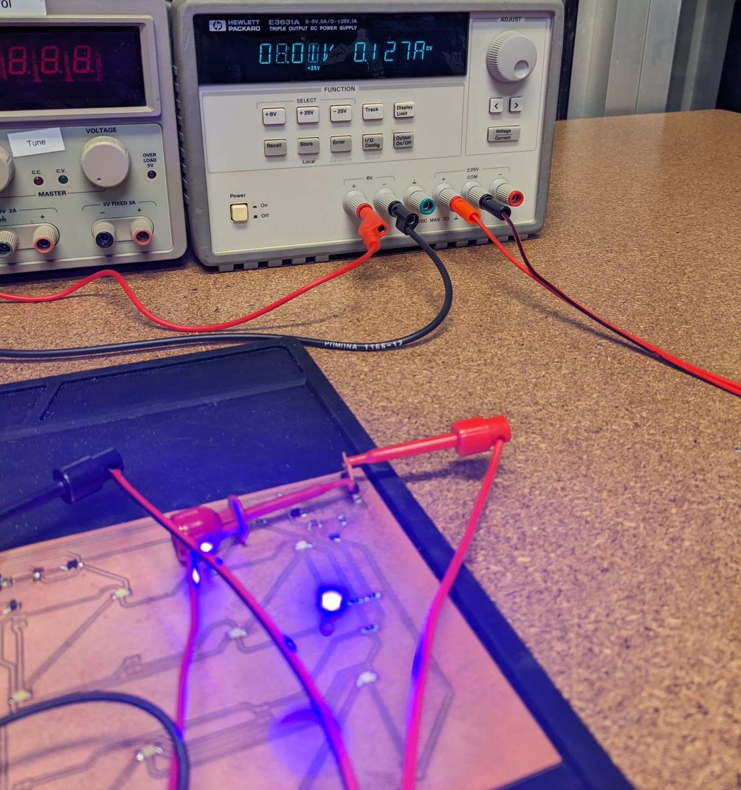
I was not able to make it to the sessions other people were planning on meeting, but big thanks to Sun, Eitan, Ben, Edward, Charlie, Ceci, Abby, Matti, Ruipeng, and Saetbyeol for their efforts and documentation of the speaker they tested! Details on their evaluation steps are here on our class site.While I did not do so with a group, I did make some measurements of the power draw of some of my components. Specifically, I wanted to make sure I had the proper power budget for the LEDs I used in my assignment. More details will be shared in the following section, but I made use of a set of white light LEDs that came from the class inventory as well as some UV LEDs that I had to order. The problem with the UV LEDs is that the forward voltage is listed but the current draw was not. Luckily, I designed my board with a pretty easy way to test my LEDs with different voltages and currents coming off a power supply. I started with my white LEDs (full array of 8), and found that because of the 10kOhm resistor on the source 5V barely turned the LEDs on if at all. I did find that with about 7V on the supply, I did get a good level of brightness out of the LEDs and a current draw of ~180mA. For the UV LEDs, I only started with two out of the 8 because UV light can be dangerous. As such, I tested the smallest amount possible for the shortest period of time while avoiding looking directly at the LEDs. I found that 8V gave a sufficient brightness out of them, which drew about ~130mA of current across the two LEDs. I will have a total of 4 parallel rows of 2x series UV LEDs, so I will need to be able to supply a total of ~520mA to power the full array.
Add an Output Device to a Microcontroller Board and Make it do Something
In Week 6 I created a board that would allow the user to play a version of mastermind (or at least attempted to, still working on programming the SMD microcontroller...). This means I had already been working with LEDs in the past, which are one of the simpler output devices. I thought about designing something that would use a speaker or a motor of some kind, but a key portion of my project is based around an array of LEDs that the user can control the power to. This ended up being perfect for this week's assignment since we talked about using MOSFETs to control a variable amount of power to a group of LEDs. I had never done before and was wondering how exactly I was going to implement it, so this gave me a great opportunity to make some progress on my final project!As usual, I followed the same flow that we have been using for designing PCBs. I started in fusion where I created my circuit diagram followed by creating the PCB schematic. In the PCB rules, I changed the design rules for the traces and spacing to be 20mils, and for most of the lines I used 25mil trace widths. I did this as a bit of an over the top precaution because I will be flowing a decent amount of current through some of the lines. At the time of selecting the trace width, the white LEDs may have drawn up to 250mA while the UV LEDs were unknown because I ordered them off Amazon. (Information on determining the power of these LEDs was discussed in the above section). I used an online trace width calculator and entered the expected current draw and parameters of our FR1 stock to arrive at my trace width. The suggestion was a few mil over the suggestion of 20mils, but my board will be very large so I can afford the extra space required. This however did create one set of issues where the 25mil trace width could not pass through resistors or LEDs because the pads were just a bit too close. I found that using a capacitor would allow the trace through, which is why some capacitors are labeled as 0Ohms. That being said, many of the traces to the individual LEDs in the arrays slim down to 20mils because the current through these lines is much less than the total current going through parts like the MOSFET or the regulator.
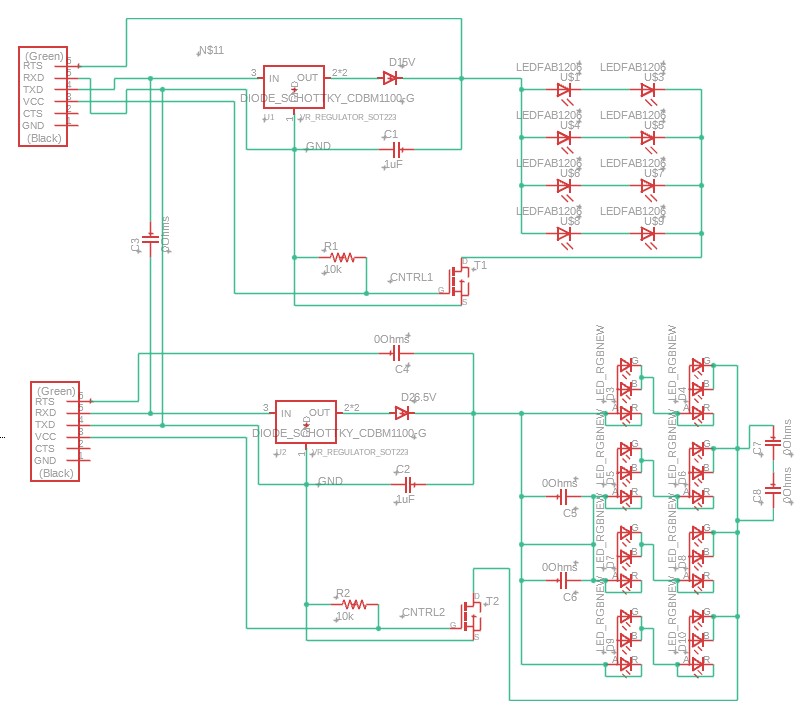
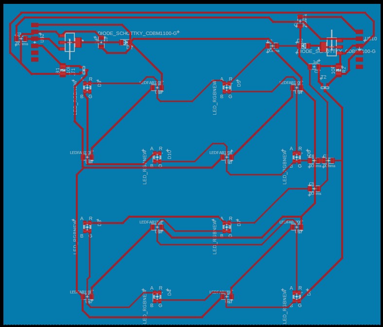
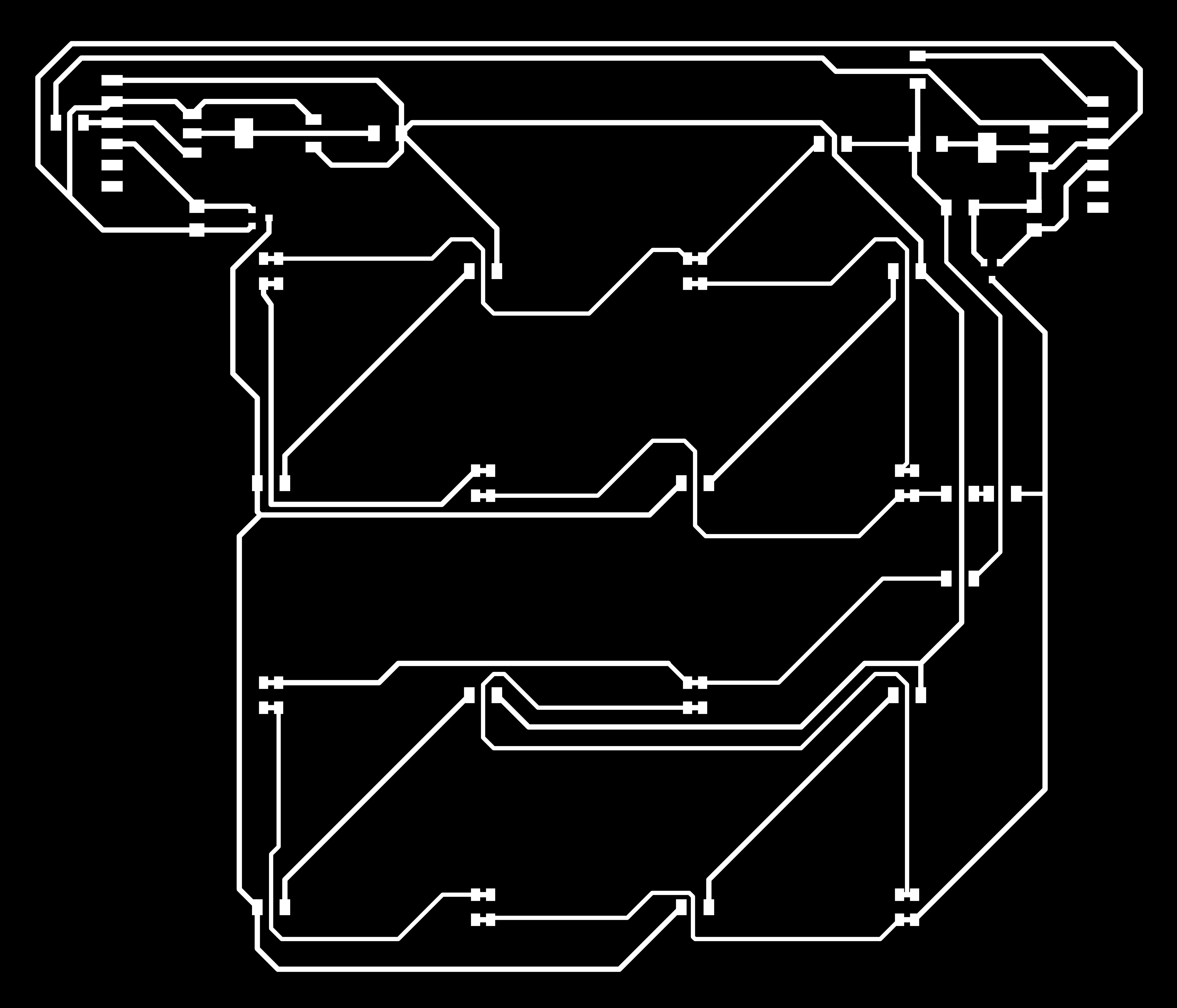

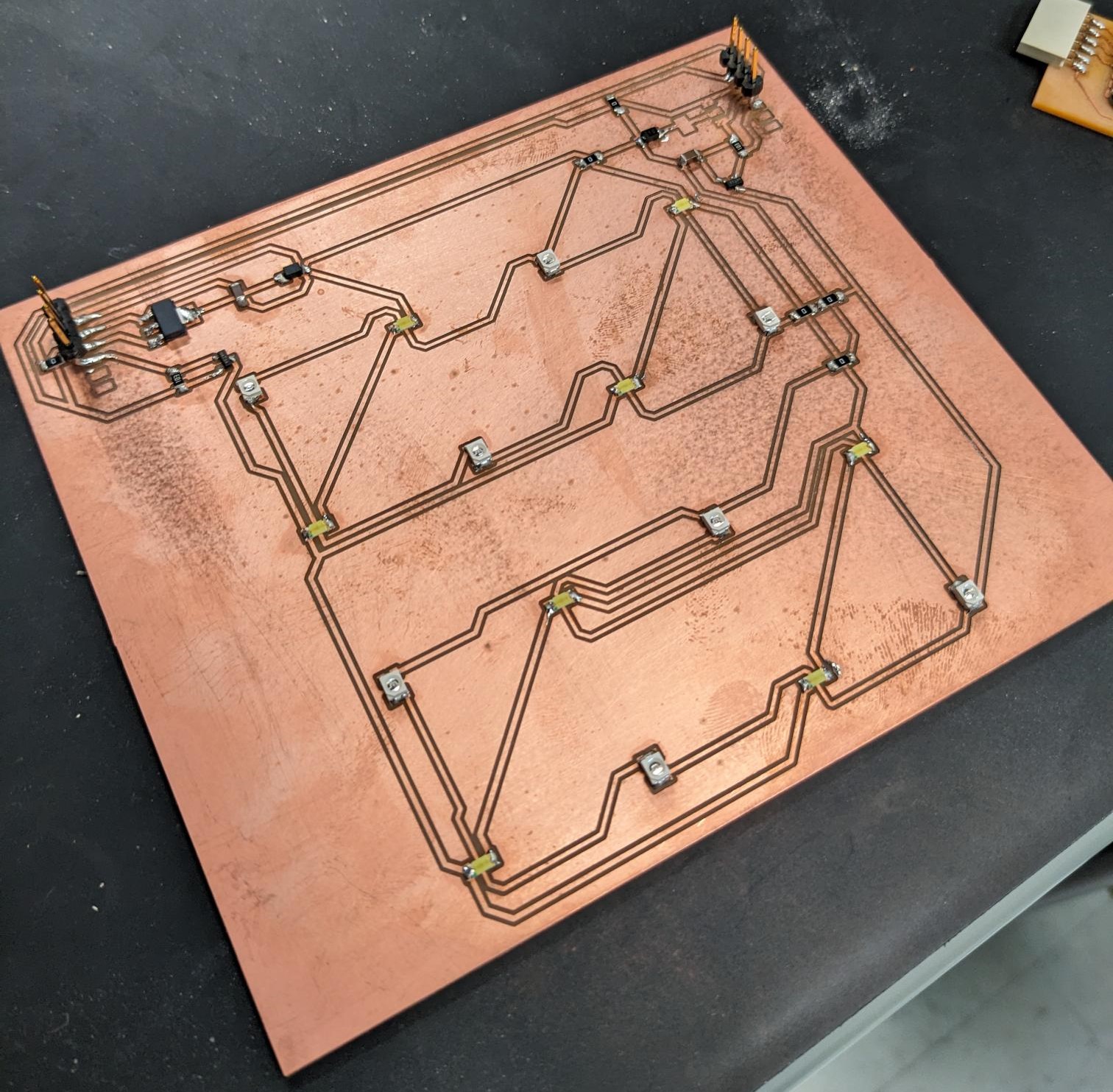
The board that I designed is essentially a 4x4 grid of LEDs, where the LEDs alternate between two different types. The first is the bright white LED from the class inventory, and the other is a UV LED that I ordered. The UV LEDs are PLCC-2, so I just used the PLCC-4 LED model in the schematic and connected the neighboring ports together. This board will act as the exposure source in the tool that I am building, and I wanted the user to be able to choose between white light and UV due to differences in types of resists. As such, the two sets of LEDs are controlled independently of one another, with a MOSFET acting as the switch to turn the LEDs on. I did leave space for a regulator on the board, but I am currently not sure the operating parameters of the UV LEDs so I will order a suitable regulator after a bit more testing. I will be controlling this board from the breakout XIAO I made last week, so the control pins for the gates of the MOSFETS are on header pins I bent to protrude vertically from the board. The power and ground are also shared between the two header pins, and eventually I will have the same power line connect in some way to the XIAO board to power the microcontroller. The last thing worth mentioning, is that I also had each set of LED's power line connected to a breakout pin (placed after a diode to prevent reverse powering the regulators). This allows me to very easily test the LED's power draw from a supply as long as the MOSFET is on. In fact, this is how I ended up testing the code for my board. I powered the board using the breakout pin to bypass the regulator and controlled the MOSFET from the XIAO board.
When it came to testing the board, I used a slightly modified version of arduino code from the class site (found under the LEDs header). All I really did was change the parameters of the PWM signal to work better with the LEDs I had used instead. As such, I didn't really feel that this satisfied the requirements for this week's assignment. However, since I would be needed some code that would allow the user to set a power level, I wrote a quick script that steps through a couple of different power levels to the LEDs. This will be easily modifiable when I am writing code that will operate on my completed project. The left video below is the modified code from class, and the right video is stepping through power levels 0%, 10%, 25%, 50%, 75%, and 100% (of a 20% duty cycle PWM signal). Unfortunately in the videos it is harder to tell the differences in the power levels, but in person they are more noticeable.