Week 7 - Computer Controlled Machining
Another name for this week is "make something big" week, because we learned about CNC machines and all the fancy things they can do when parts are designed right. This included discussion on target materials, different types of end mills (and the difference between them and drill bits), fixturing, and key tool parameters.
Assignments:- As a group do our lab's safety training
- As a group tests runout, alignment, fixturing, speeds, feeds, materials, and toolpaths for your machine
- Make, design, and assemble something big (on the ~meter scale)
- Extra credit: Don't use fasteners or glue
- Extra credit: Include curved surfaces
- Extra credit: Use three-axis toolpaths
Lab Training + Design Rules
Dan created a spreadsheet for our section where we could sign up for tool time on the CNC as well as sign up for one of a number of training sessions to go over the tool and safety. Some additional information useful to operating the tool also came during the recitation that was right after the training session I attended. Further documentation is on the class page as usual.
Making Something Big
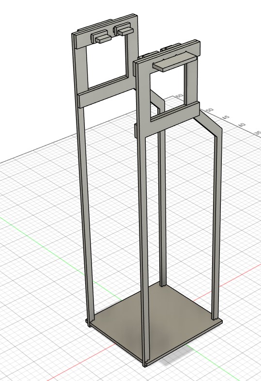
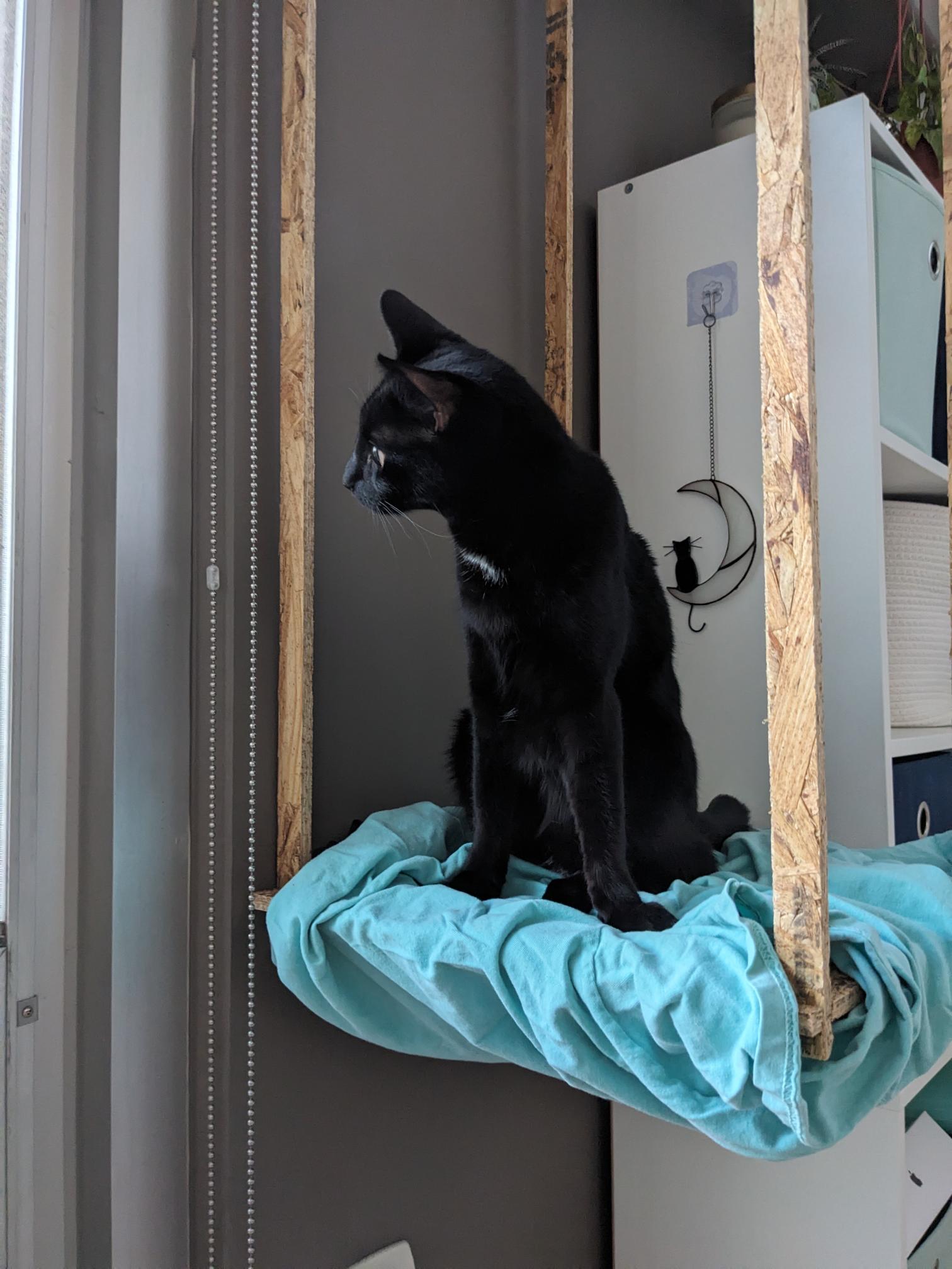
For my assignment this week, I decided to make a sitting/viewing platform for my cat Raven that would hang from a beam in front of a window in my apartment. I specifically chose a section of the window that is not too obstructive, where the platform would end up being just a bit above a monitor that my fiancee uses during her workday. I measured the beam width and height, the height for the supports to hold the platform, how much space there is to the window, and how much space there would be laterally between the two window beams. With these measurements and the thickness of our stock plywood (~.433in), I designed the structure below in Fusion 360.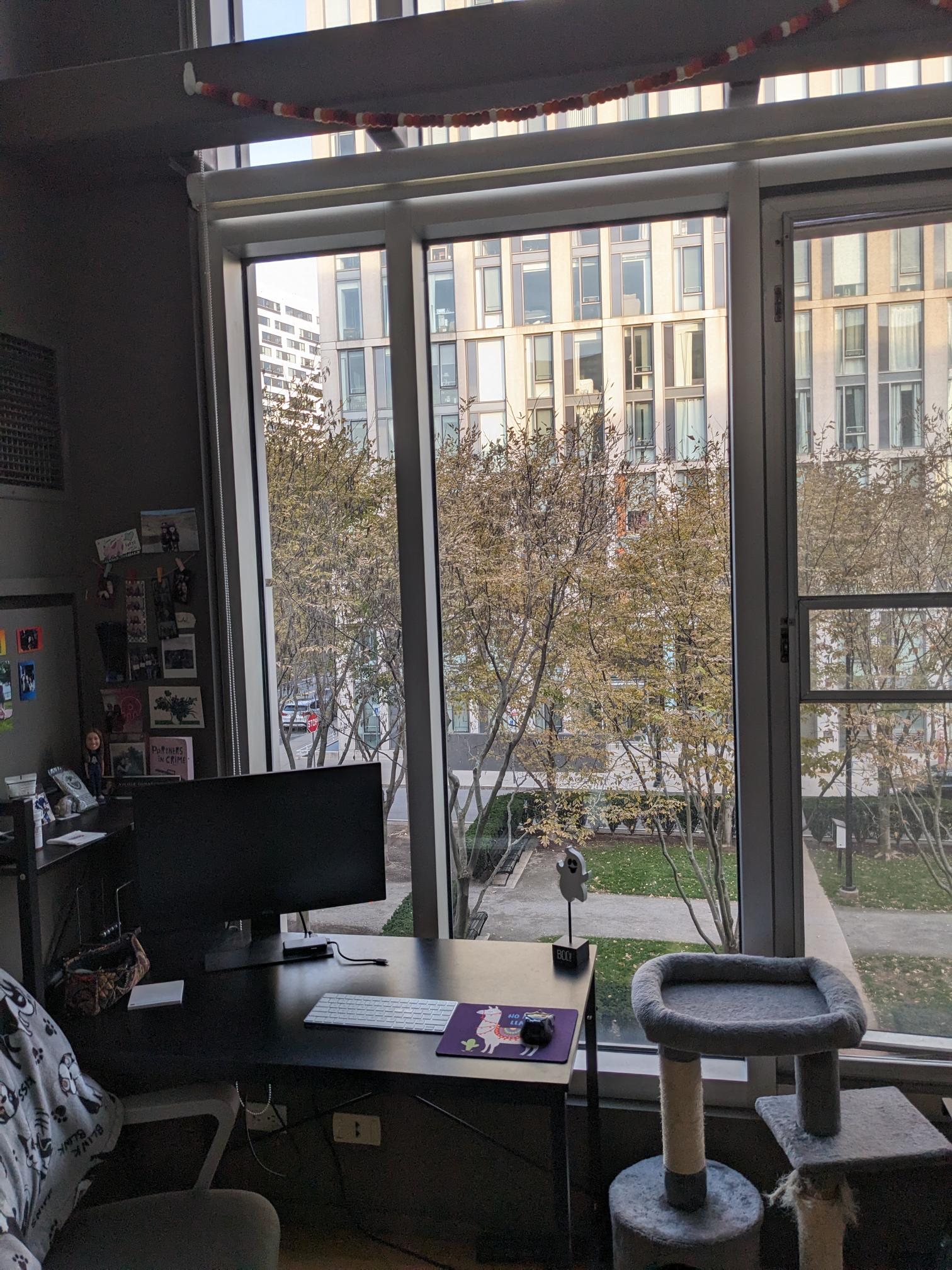
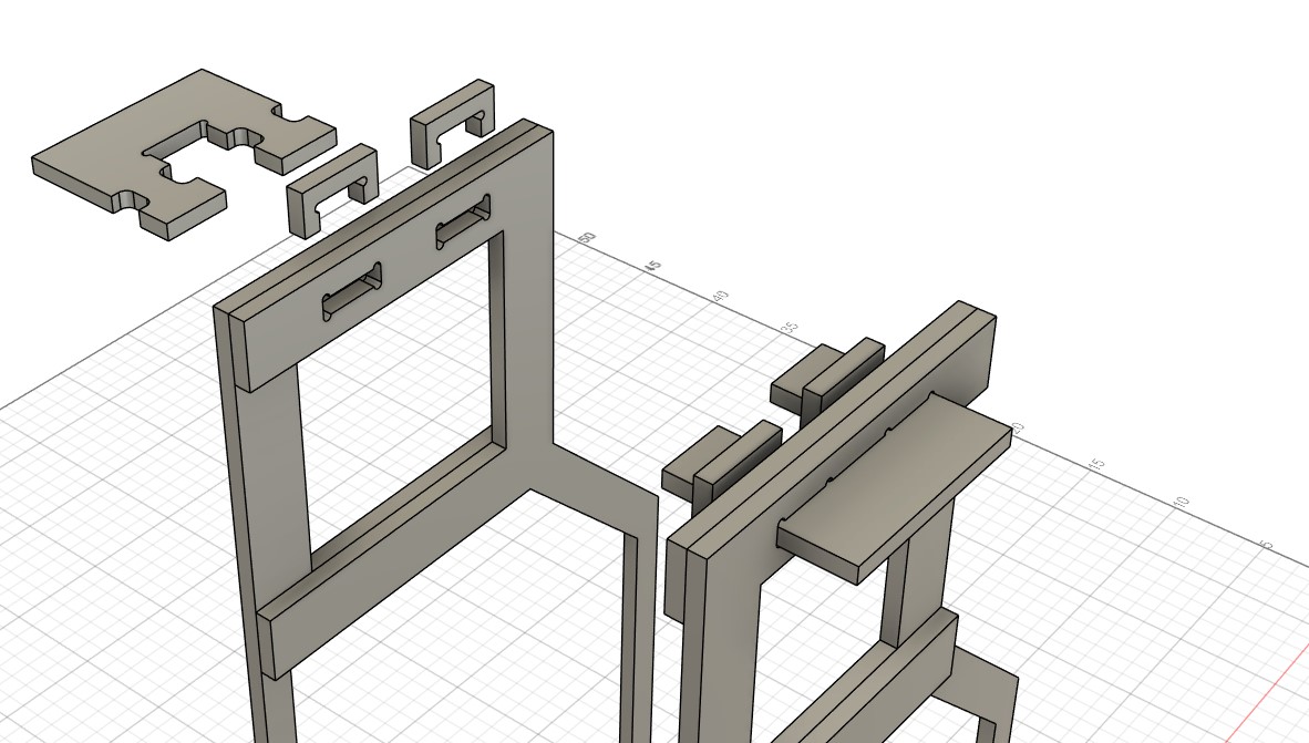
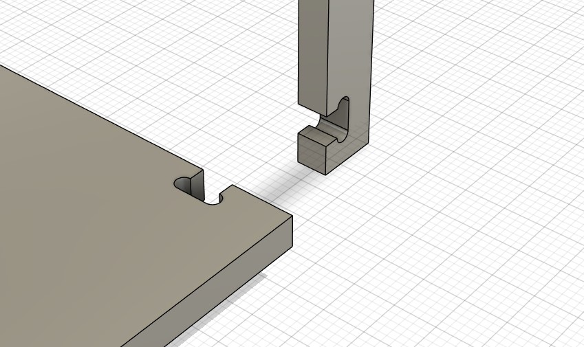
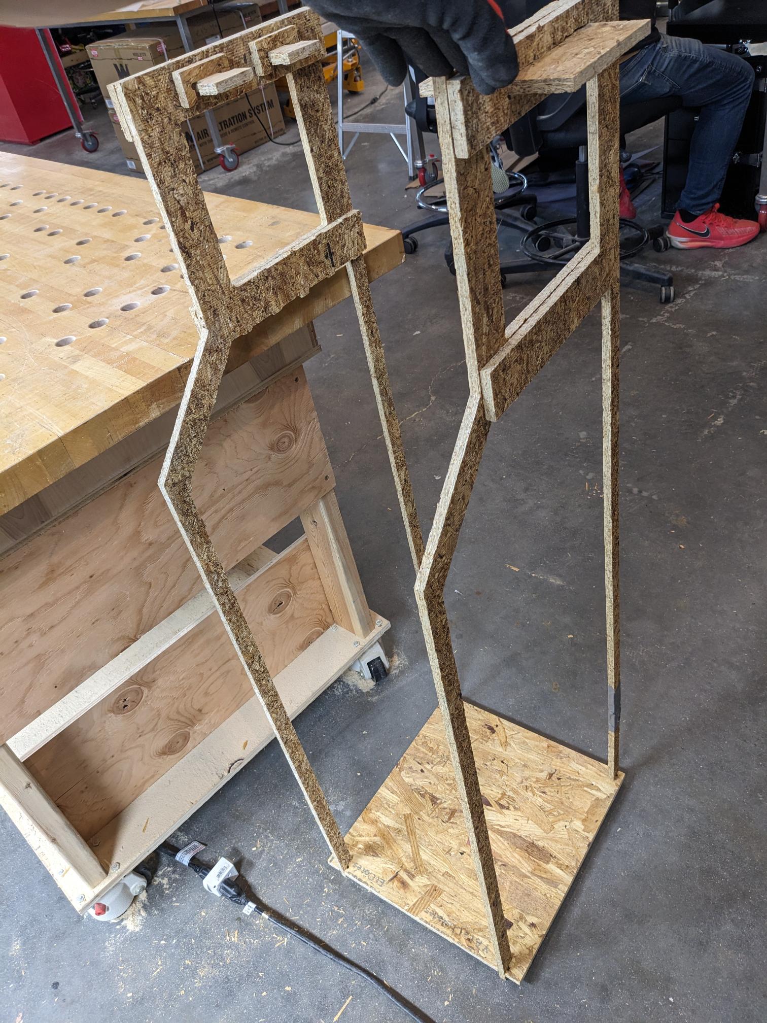
One of the key things we learned in class/the recitation was that we would need to include structures called 'dogbones' in order for the pieces to actually fit together. This is because a circular end mill cannot actually cut a corner, so if it can be designed in there should be an extra tool cut to make the right angle joint possible. I make use of these for pretty much all of the joints in my design. They are used for the long supports and bottom plate to fit together, and they are used to make sure that my pinning pieces are able to slot into the holes I made for them in order to keep the supports in place. Examples of these features are in the next image which also depicts the locking mechanism I used to secure the hanging supports. Each support has two dogbones cut into it such that they line up and can accommodate a pronged insert. Just in case the insert has some wiggle room and could potentially come loose, there are then two additional clips that come down and lock the insert from being able to wiggle free on its own. This is the main portion of how the design is assembled without the need for fasteners/glue for the extra credit assignment, the other areas of assembly are simple slots on the bottom plate and hanging supports that seat into one another.
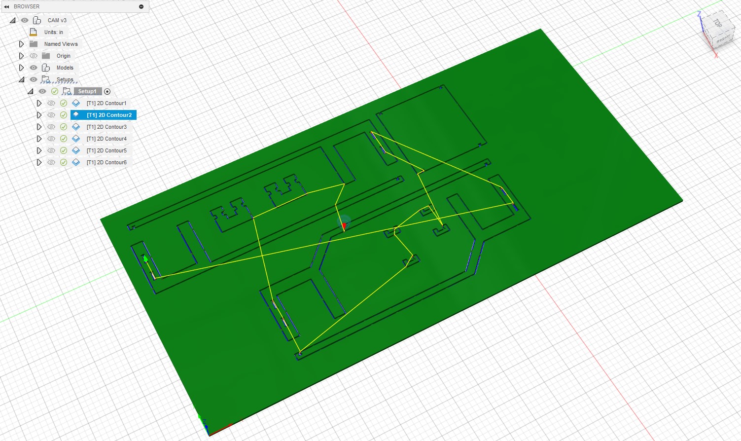
I then created a new file and went to the manufacturing tab in order to set up the CAM for my parts. From some prior experience, I prefer to place all of my parts first and then set up a fixed stock size according to the size of the plywood we have on hand. In this case, we were given a 4ft by 8ft piece of plywood that was about .433in thick. With all my parts in and flattened to the same plane, I then set up the stock around the parts. One of the key steps we needed to do was to make sure the XYZ axis was oriented properly, and when in front of the computer the XYZ zero point is the close right corner fo the stock. More details on the stock orientation is included on the group work page.

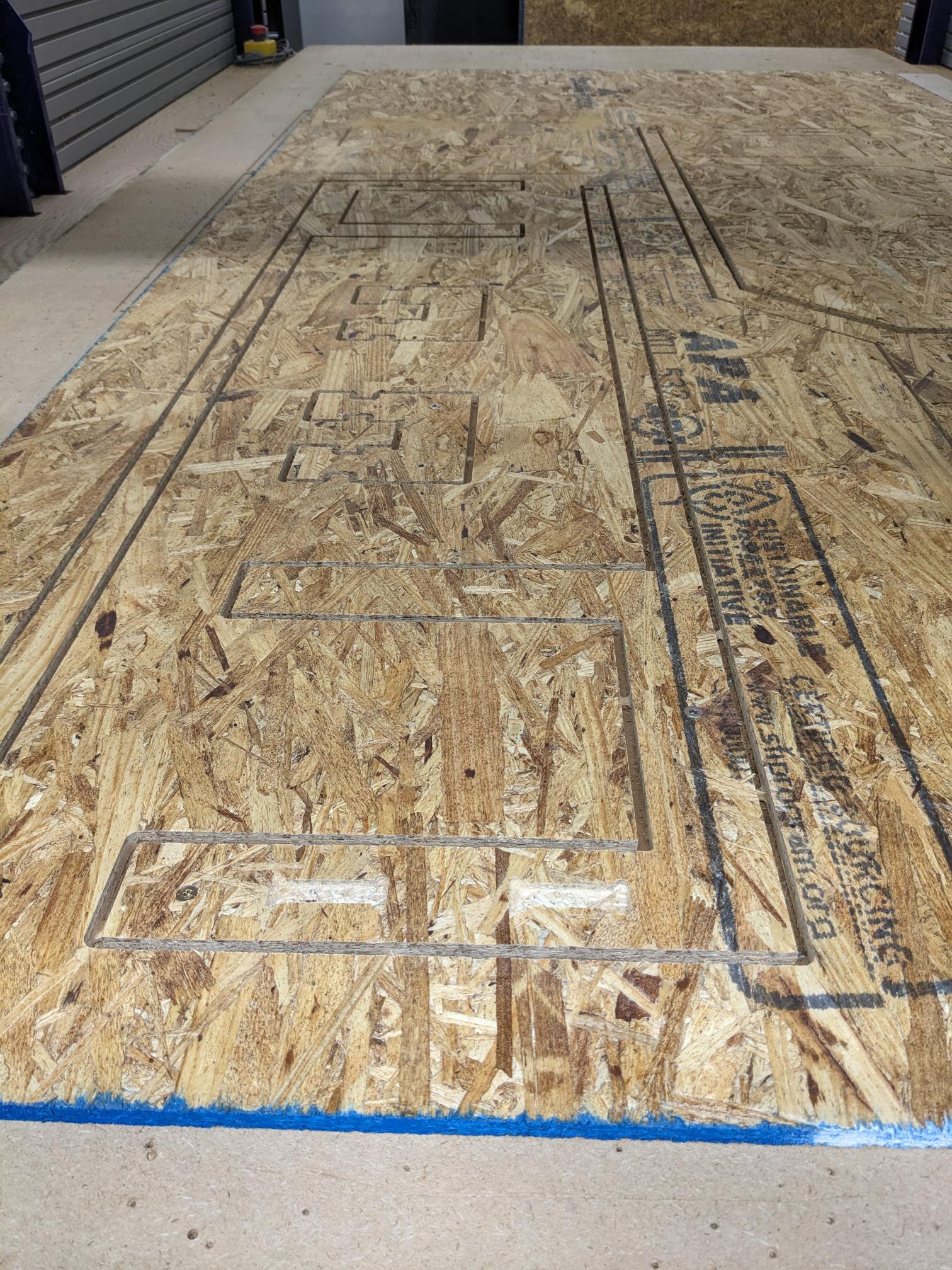
Once my stock was setup, I then created two cutting passes. The first of which used a downcutting endmill because it would not tear the plywood up and create a rough finish on the part. That being said, this does also force the cut material down into the cut which is not very good for deeper cuts. Therefore, a second cut would then be required with an upcutting endmill to get through the rest of stock (and to also prevent tearing the plywood on the bottom of the stock, basically the reverse benefit of using a downcutting endmill on the top surface of the stock). For these jobs I used the contour feature, where the first cut was based on the top contour and the second cut was based on the bottom contour. As such, the first cut did a single pass with a depth of .2in into the stock and in terms of special settings that's mostly all that was required. The second cut required multiple depths to minimize problems with the endmill as well as tabs that would hold the part in place and prevent them from potentially jumping their way into the endmill. I set my step down depth to be .18in, and the tabs were .15in thick with width of about .25in and a spacing of an inch or two. Both cuts were made with the same suggested feed rate of 150in/min and an RPM of 10,000. The first cut to a depth of .2in is on the left and the second through cut with tabs is on the right.

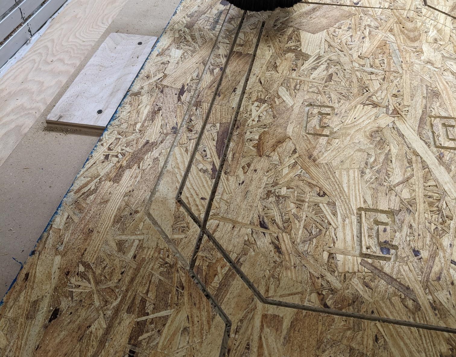
My first cut went well (left image) and I did not encounter any issues. During my second cut however, that is when I had a number of different issues. The first problem I encountered was that my stock was bowing upward due to the force of the upcut bit, and as such the bottom of central portions of the stock were now above the height of the tabs. This led to some of the central pieces having no surviving tabs so they started to shake loose. With advice and help from Dan, we paused the cut job and secured all the pieces with additional screws. This is much easier to do after the second cut since we already knew the path the tool was going to take. It may be a bit hard to see but some of the added screws are in the image on the right.

Sadly this was not the end of my problems, but at least initially resuming the job appeared to work well. The tool was cutting one of my hanging supports and it did the first step down cut properly. However, on the second step down cut for some reason it made a turn much earlier than it was supposed to and basically cut right through the support leg. As I watched this happen I stopped the job and ultimately ended up aborting it for fear of the tool having lost its zero somehow. After talking with Dan and looking through my CAM, we could not find where the problem was but we would like to take a further look at the g-code when we have more time.
This meant I needed to create a new set of g-code that would cut the piece I lost as well as any pieces that the tool did not get to since they were after where the job ended. This was simple enough to do, I just added them into the CAM file and created new cuts where I only selected the targeted contours. With the new code checked, verified, and uploaded I started another cut job. As the tool got to some of the smaller locking pieces, board bowing once again became an issue and they started to pop free. The first piece that shook loose stayed in its pocket and would not have affected the tool path so I let it be. The second piece however was slightly protruding so I paused the job and waited for everything to stop moving before removing the parts. After resuming the job, the spindle plunged straight down in the Z-direction and was spinning up against my stock creating smoke. I immediately pressed stop on the program and quickly followed it up with the e-stop to stop any additional problems. Luckily the spindle has a spring that pulls it up when the e-stop is pressed, and Dan help me with the laser fire blanket to put out a few embers that had formed due to the friction.
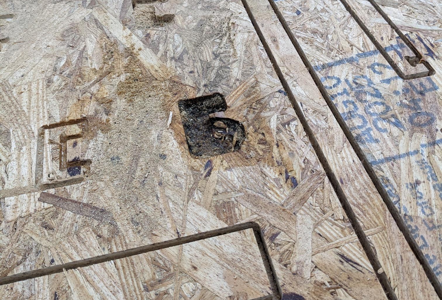
Once again we spent some time debugging, but could not find a cause for the plunge in the CAM file or simulation. Later, we made a report to Prof. Gershenfeld who put us in touch with ShopBot reps, where we learned that depending on the software version there is a known bug that causes the spindle to drop in Z upon resuming a job (so please be warned and keep this in mind!). This was obviously a concerning event and I was definitely more paranoid every time the tool went for a plunge as it finished cutting my material, but luckily the remaining parts came out without any other problem.
After removing all the screws, there were some parts that were loose and could be removed from the stock. All the other parts I trimmed the tabs with the reciprocating saw. All parts were then sanded to remove annoying placed tabs, to clean up some of the edges, and a piece or two needed to have finishing touches made to the dogbone cuts. Assembling the structure actually went quite well and the slots/stays I designed worked quite well in preventing too much movement of the main structural pieces even without using adhesives/glue! (Although one of the supports was a bit loose due to the plywood delaminating a little, which is why one of the legs is duck taped)
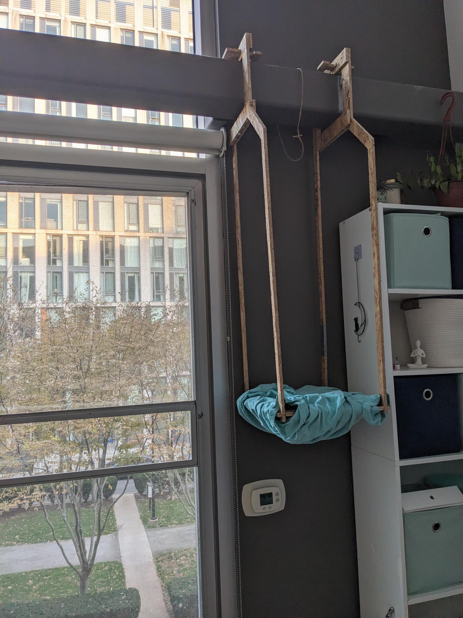
When I brough the hanging platform back to my apartment, I quickly found that I had made one crucial mistake. All the measurements I took did not account for the blind... Luckily, since the beam was so long, there is a second section that is a perfect candidate and it does not have any interference from the blind but it is not as accessible or as good of a view of the window. Regardless, I used some old t-shirts to make the bottom platform a bit more comfortable and set it up for Raven to enjoy.
- BottomPlate.ipt
- HangerBack.ipt
- HangerFront.ipt
- TopSlot.ipt
- TopSlotStay.ipt
- Assembly.f3z
- CAM.f3z
- CNC Cut 1 g-code (downcut endmill, nominal assuming the cut works fine)
- CNC Cut 2 g-code (upcut endmill, nominal assuming the cut works fine)