Week 11 - Machine Building Week
This week was the notorious machine building week! We were given a starter kit with some basic equipment like linear rails and ball bearings, and we had one week as a section to design a machine that does something.
Assignments:- As a group design a machine that includes mechanisms, actuation, automation, function, and user interface
- Build the mechanical parts and operate it manually
- Actuate and automate your machine
- Prepare a demonstration for the next class
- Document the group project
- Document your personal contributions to the group project
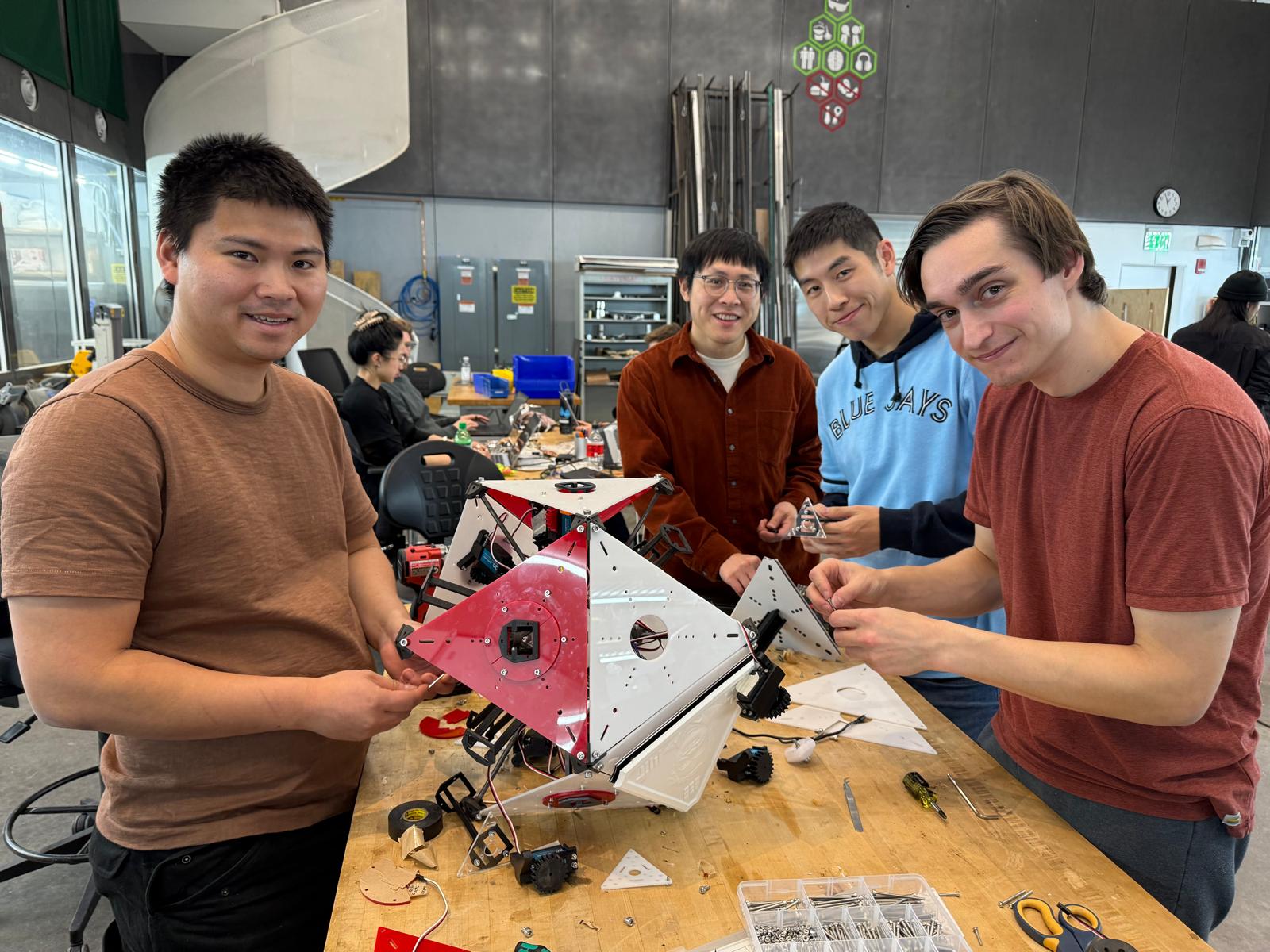
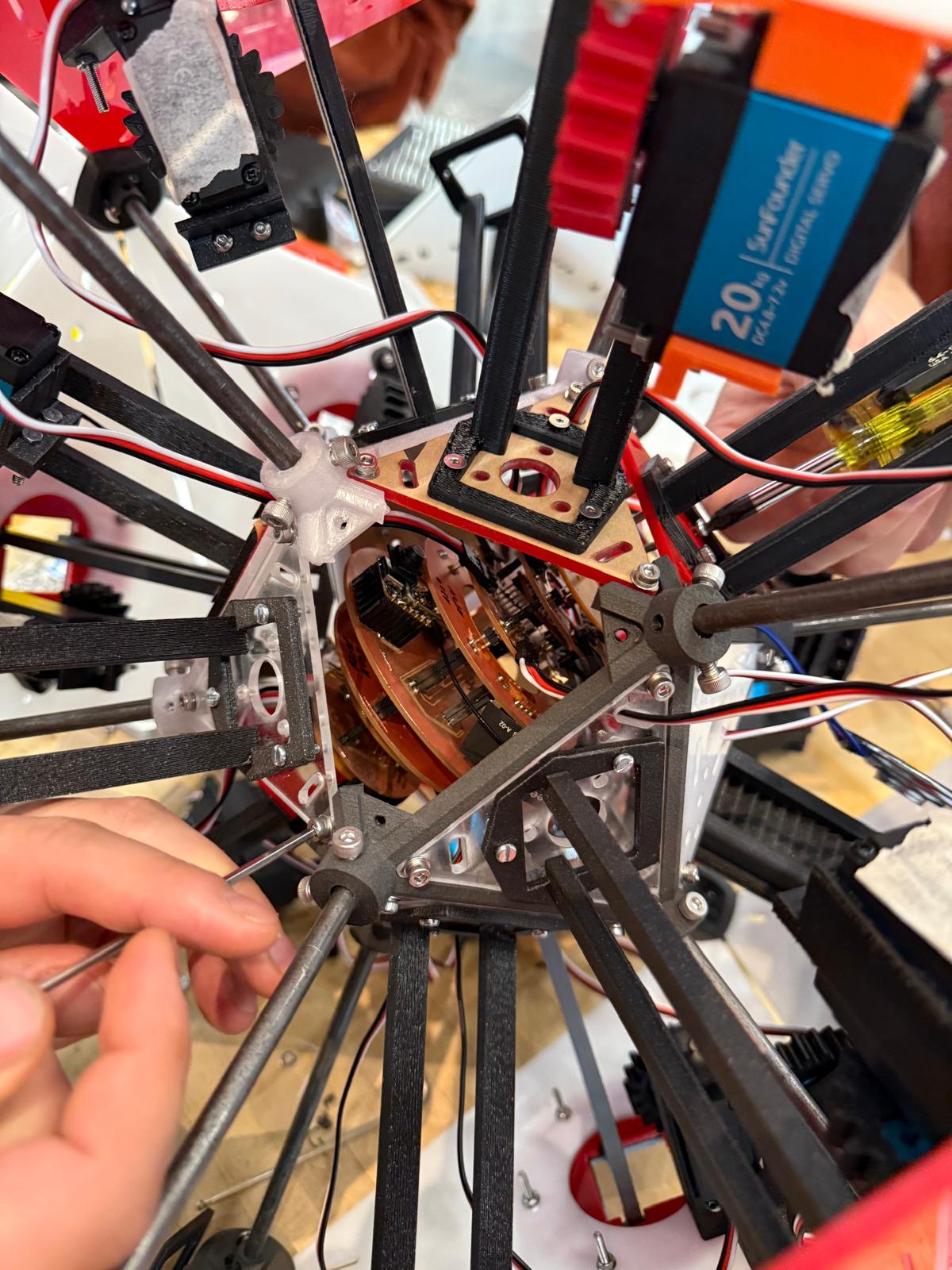
CBA Section's Neilbot!
Our website showing off our amazing Neilbot project can be found here. This site contains our creative presentation video, our documentation video, and sub-team sites that go over the relevant details for that team. In my case, I primarily contributed to the electronics sub-team found here!
My Personal Contributions
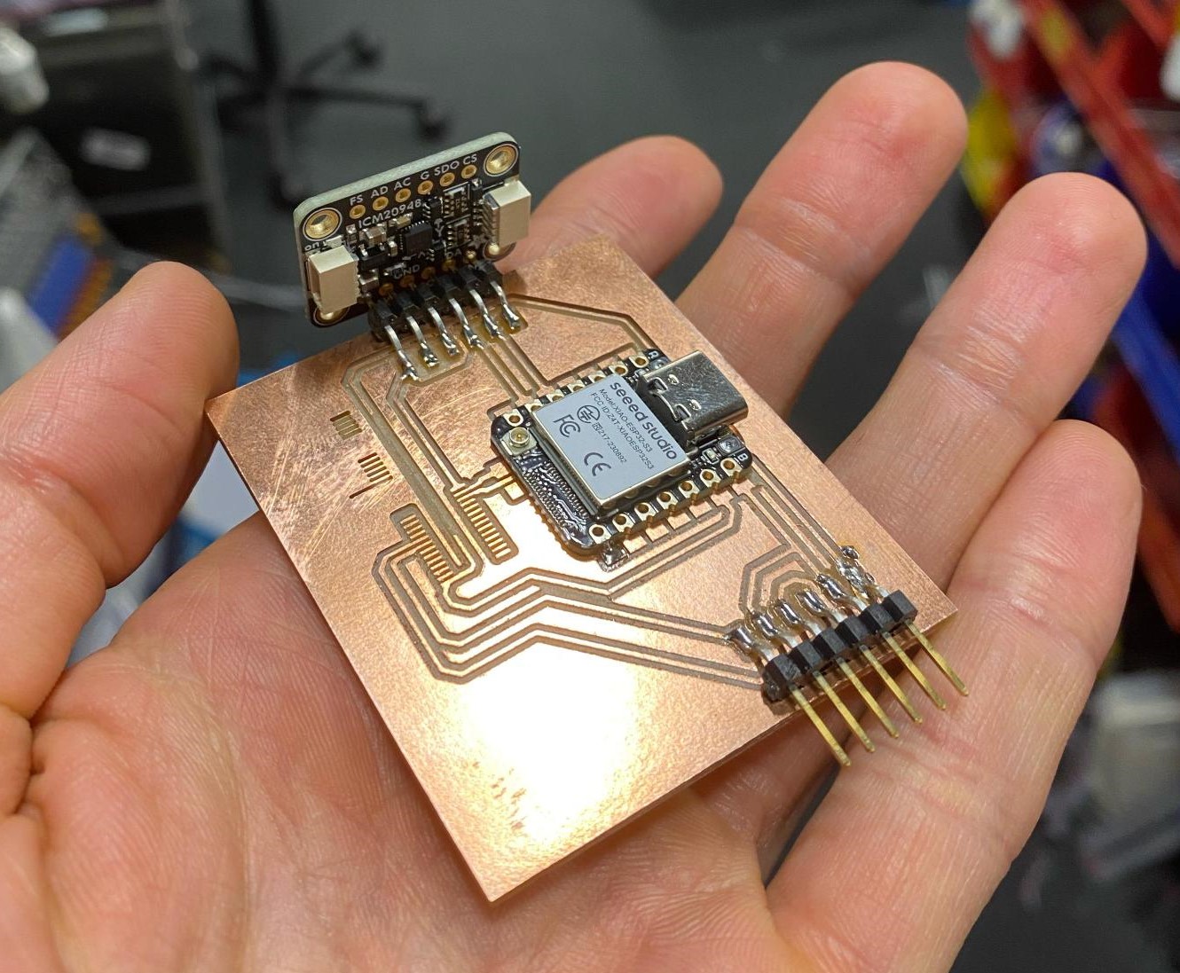
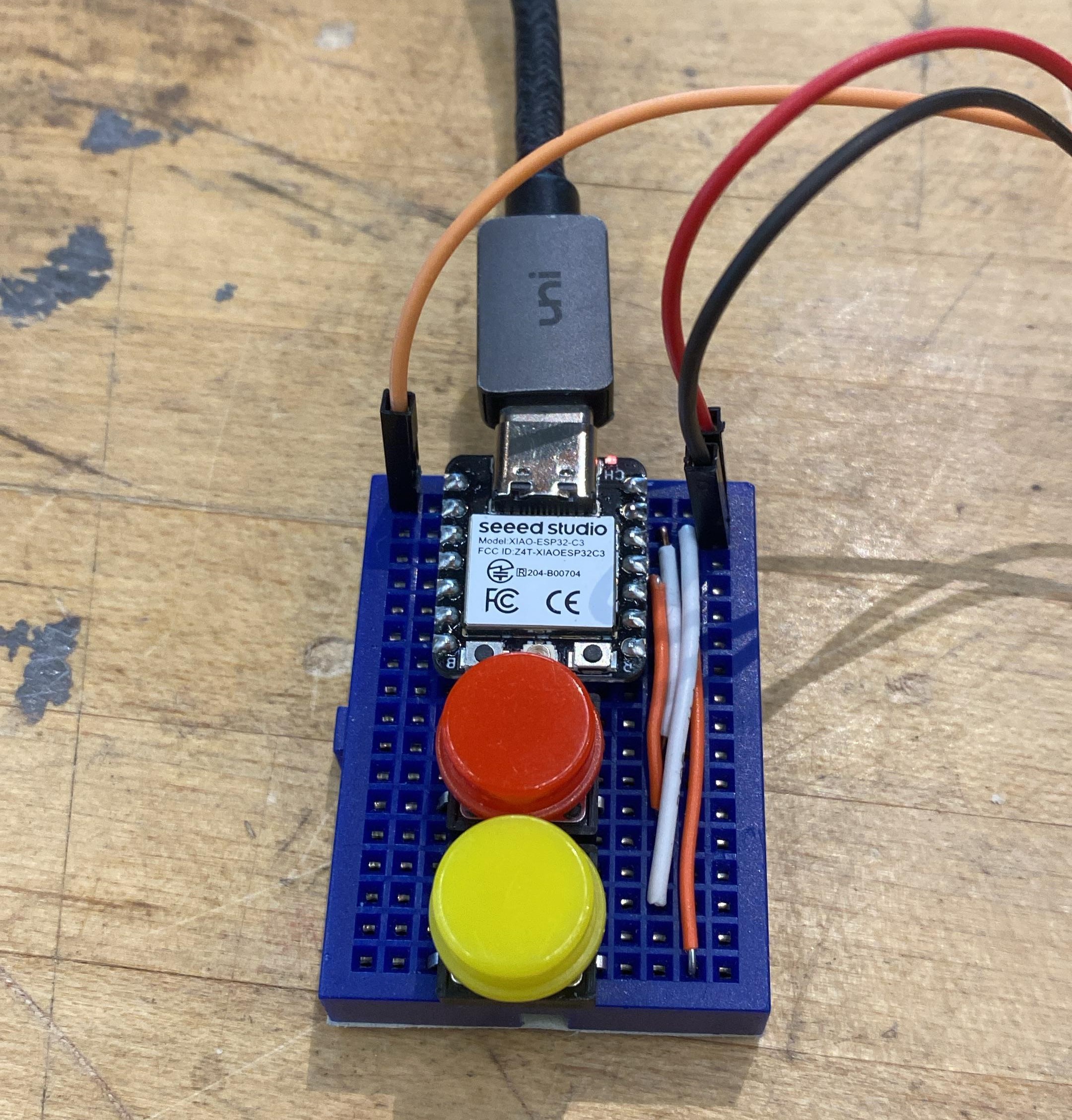
When we were intiially brainstorming/developing our idea, I signed up for the electronics team because that is where I felt my skills would be most impactful. As our section started to hone in on the project that would eventually become the Neilbot, we were able to get a better idea of what would be required to operate our machine. As the electronics team, that meant we were tasked with picking out all the components necessary for operating the 20 servo motors, integrating battery power, sensing our position/orientation, and adding a microphone for playing sounds. Some of these components were very easy to determine, we had breakout IMU and speaker driver boards in our class inventory, so we planned on using those. For battery power, there was a regulator breakout board that came with the batteries that we were able to pick regulators based on. And finally, Dimitar found PWM driver chips that take I2C inputs and can operate up to 16 PWM signals out which are perfect for easily controlling our servos.Right off the bat, we wanted to try to get some parts into the hands of the software team so they could start to figure out the servo and IMU interfaces. Dimitar put together a breadboard or two while Ben and I designed and cut an initial PCB. This PCB had a XIAO board, the IMU breakout, and the PWM driver chip connected to two servo pins. Ben had to modify the cutting parameters in order to get the PWM chip's traces to resolve properly due to the package type, but we were able to successfully produce a board and deliver it to the software team. While Ben was soldering the components for the V1 board, I also put together a small breadboard with buttons for the mechanical team to test the actuation of the servo. Surprisingly, they ended up using this pretty late into the project for the various mechanisms they designed.
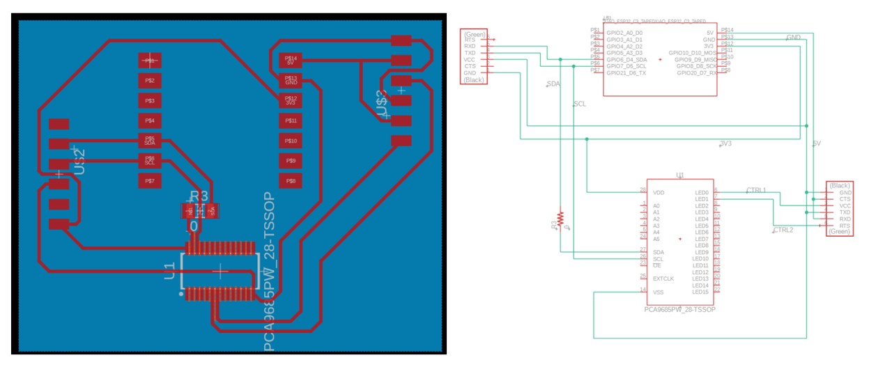
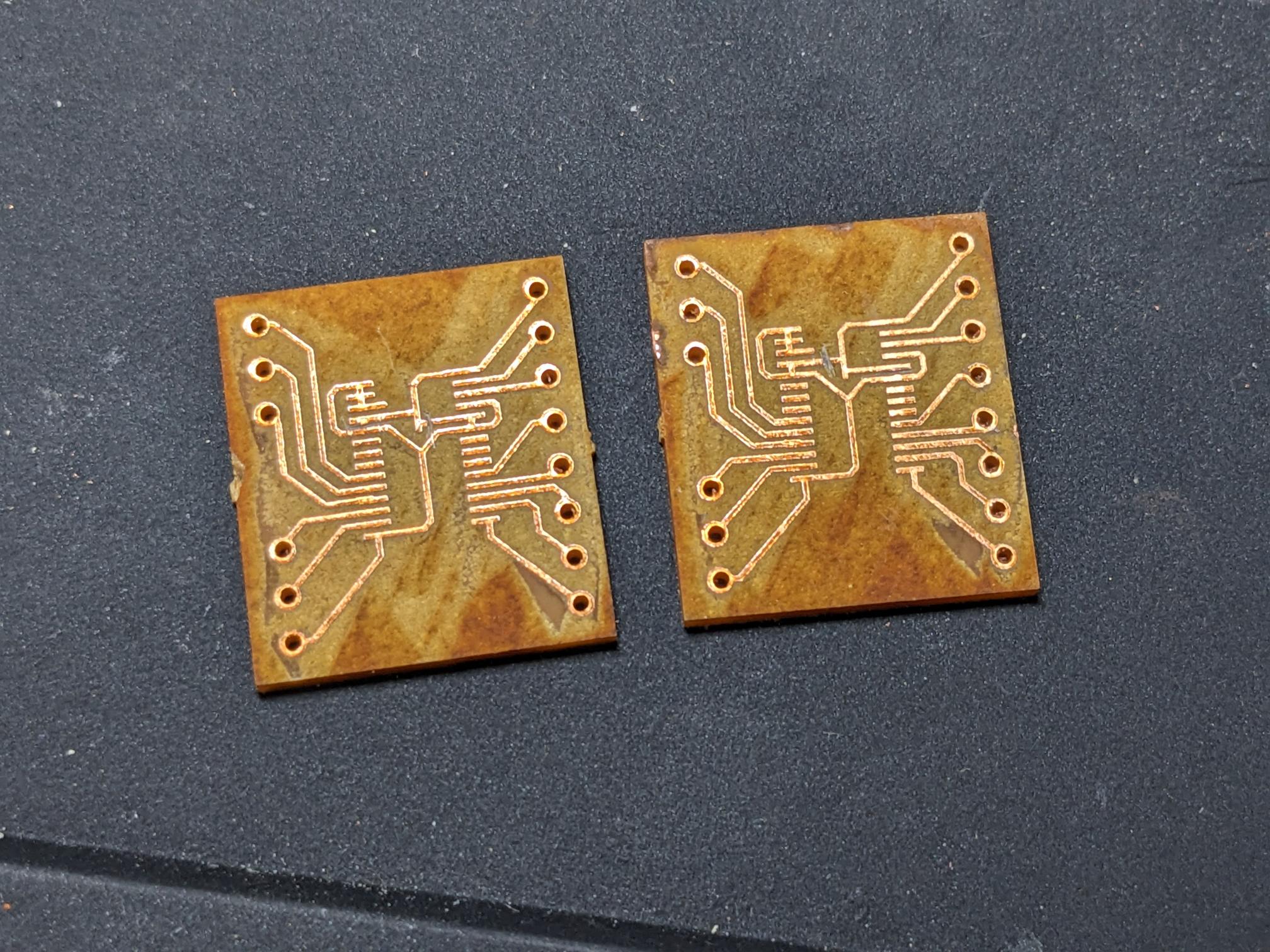
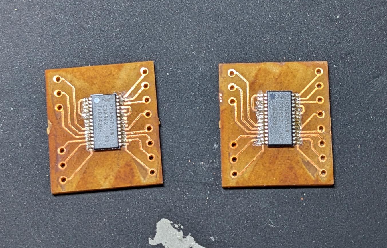
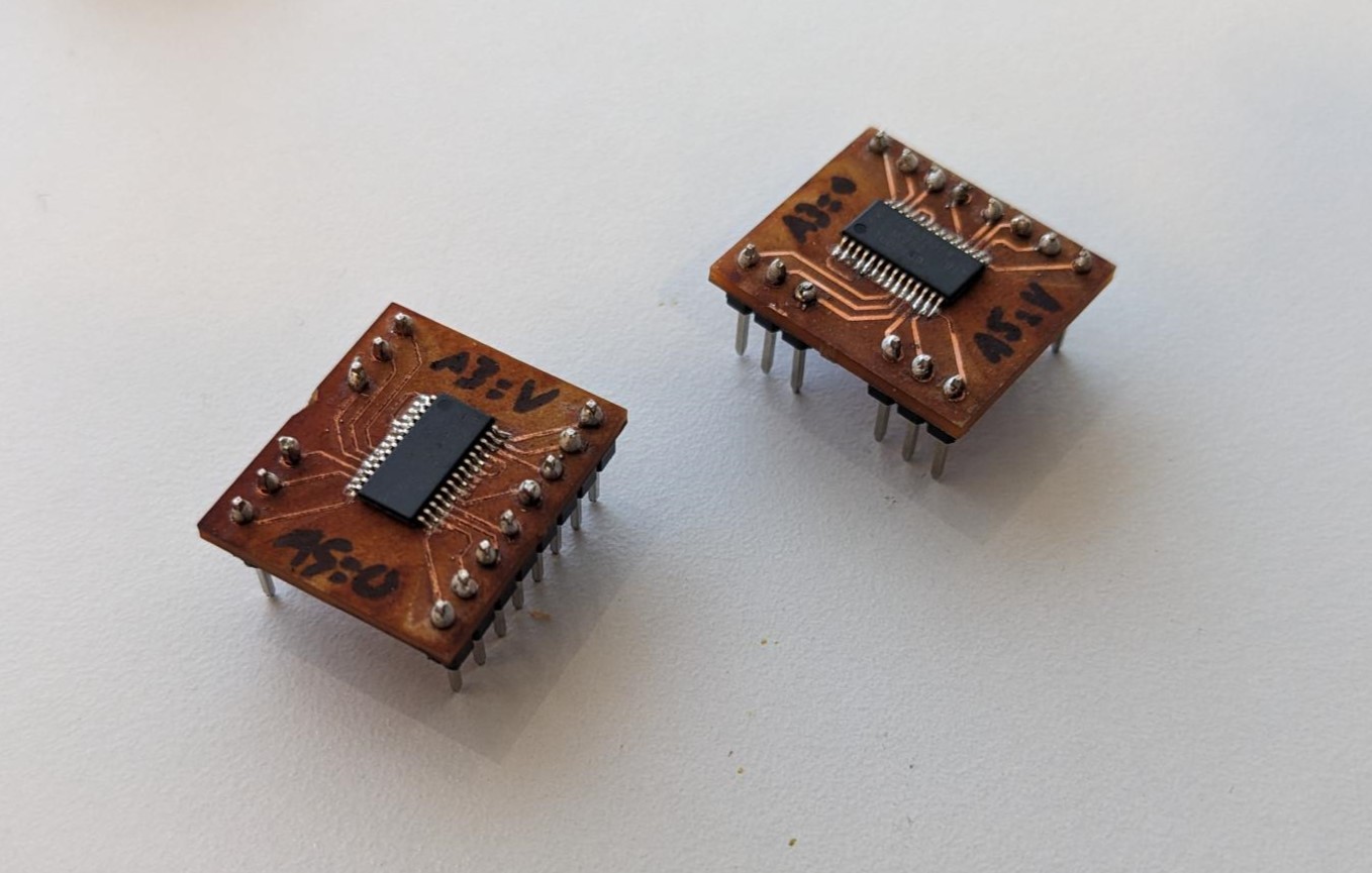
Following the creation of the V1 board, we determined it would be easiest if we made our own little breakout boards for the MUX PWM servo drivers. I took on that responsibility and designed a small little PCB to cut on the XTool F1 laser cutter. One of the requirements we had was a way to set the addresses to make sure that the two driver chips were not on the same communication line. In hindsight, I should have probably used 0Ohm resistors to jump VDD to the desired address pins, but instead I just connected all address pins to VDD and GND (which made the schematic a bit weird) and then cut them manually after the boards were made. Agai n I should have just used resistors, but this did work exactly as intended! On a brief side note, I found that in order to get the pattern on the laser cutter control software to align with the image, it needs to be shifted .6mm to the left and .3mm up (6 left arrow taps and 3 up arrow taps). This is for the center of the bed, it shifts slightly on the outer extremities.
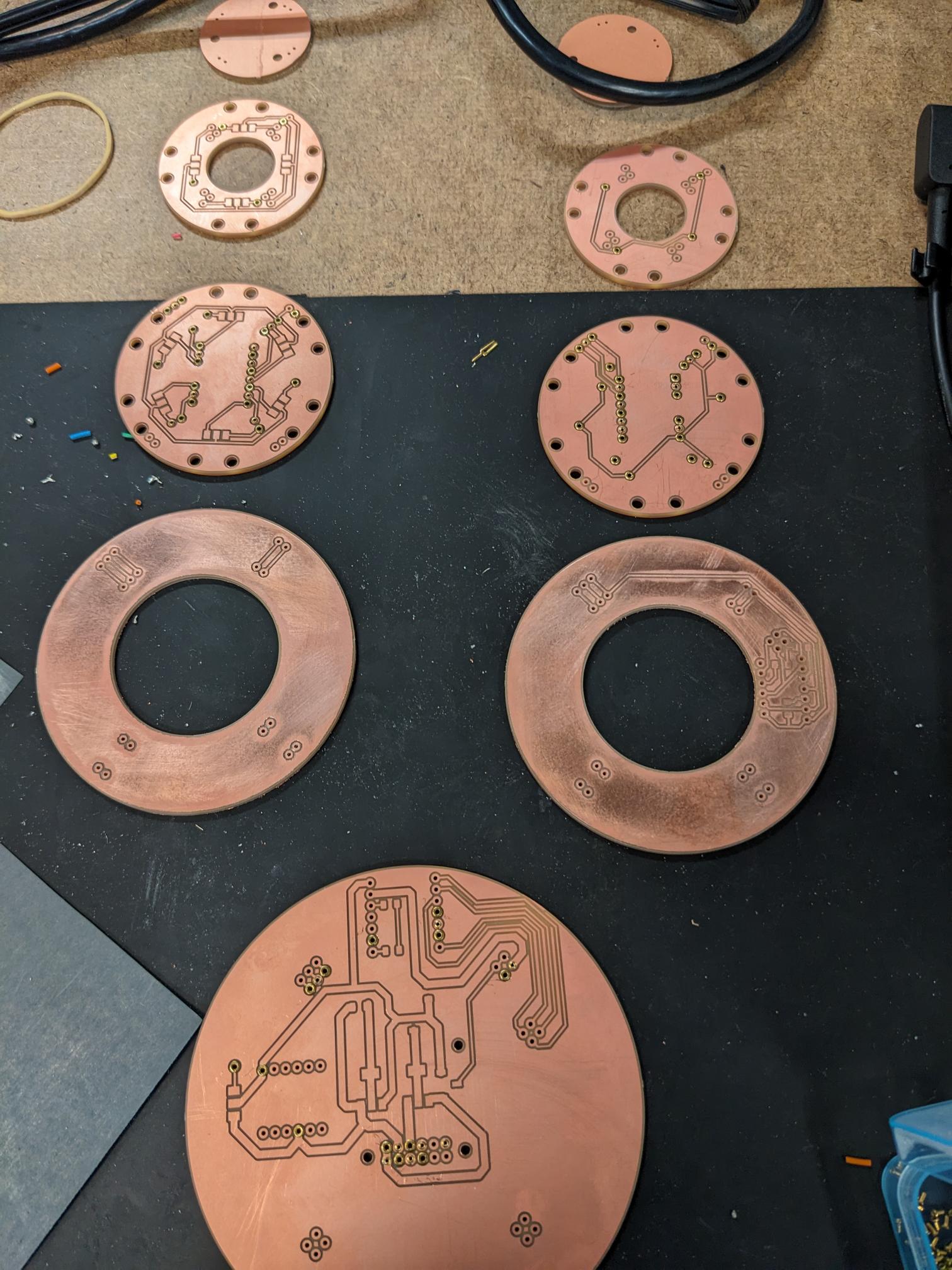
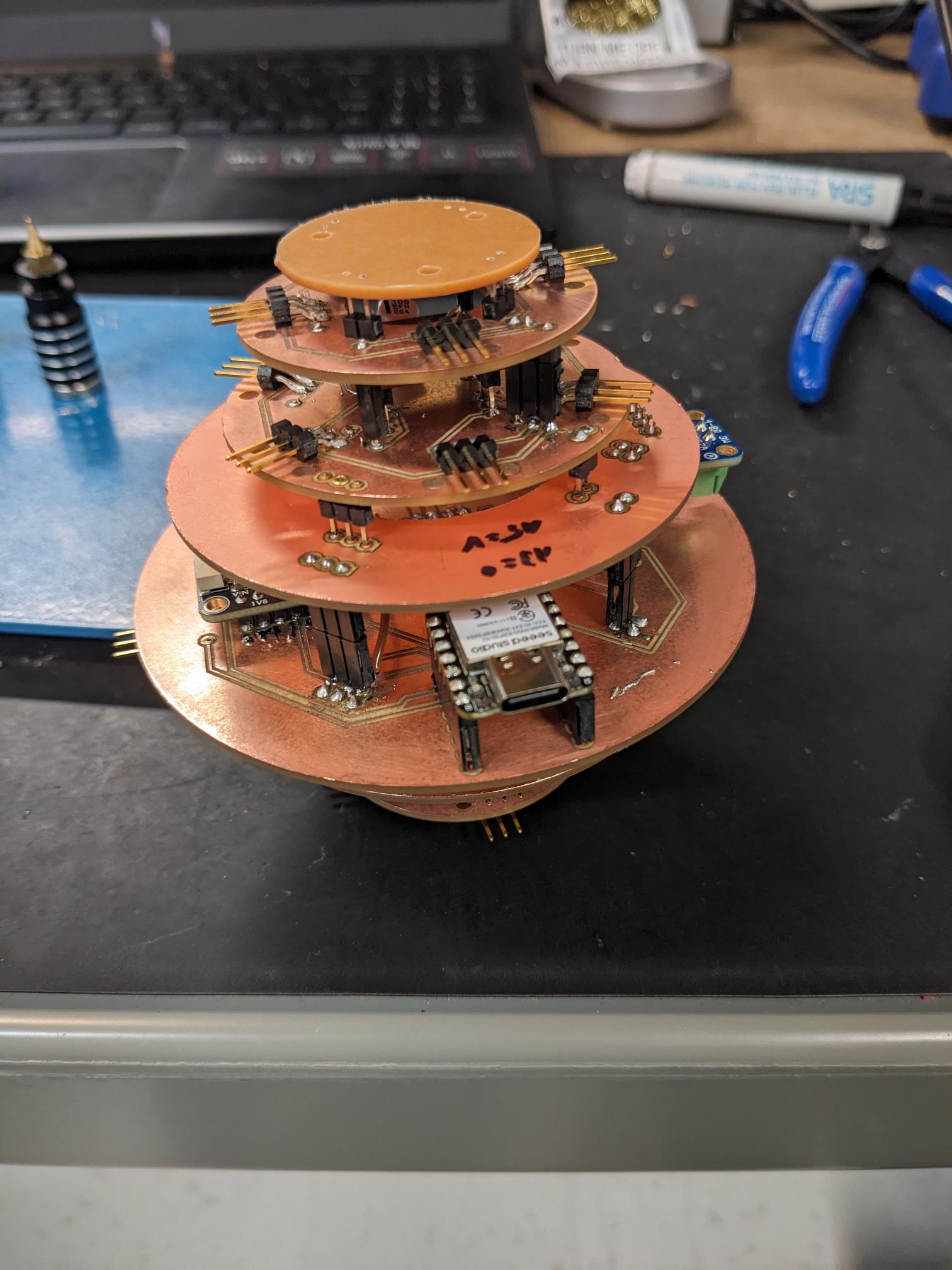
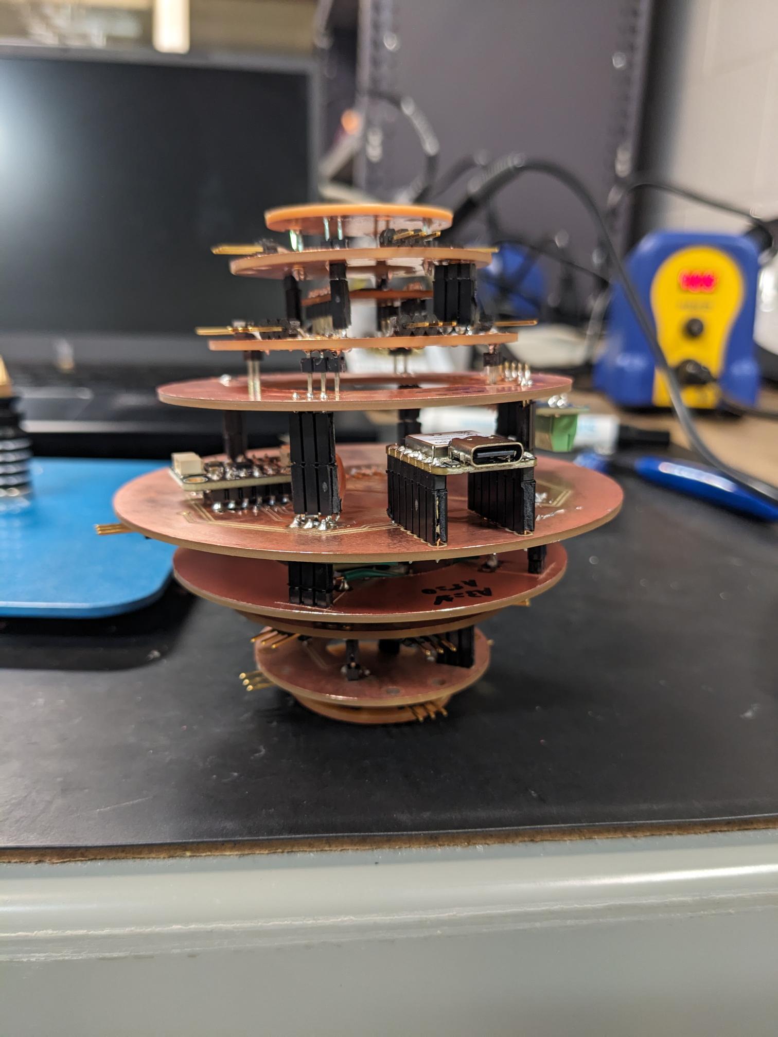
While I was making the PWM boards, Dimitar did a fantastic job of designing a complete V2 board that would be sufficient to run our minimum project requirements. At some point however, we talked about making a 3D PCB because it would be "more ball". So my next task was to take Dimitar's design and transform it into a multi-stack PCB, during which any bugs they encountered I would be able to adjust and account for. It did take a while, but I was able to create a schematic that successfully routed all components across multiple layers. The two smallest PCBs on the end of the stack also had the same mounting holes as the V2 board for simplicity.
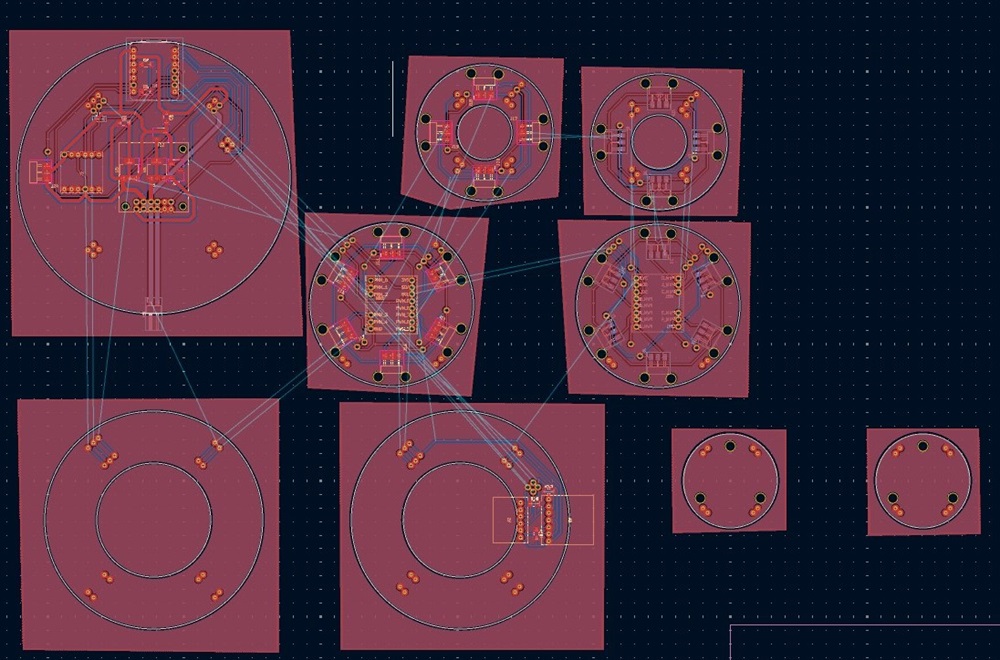
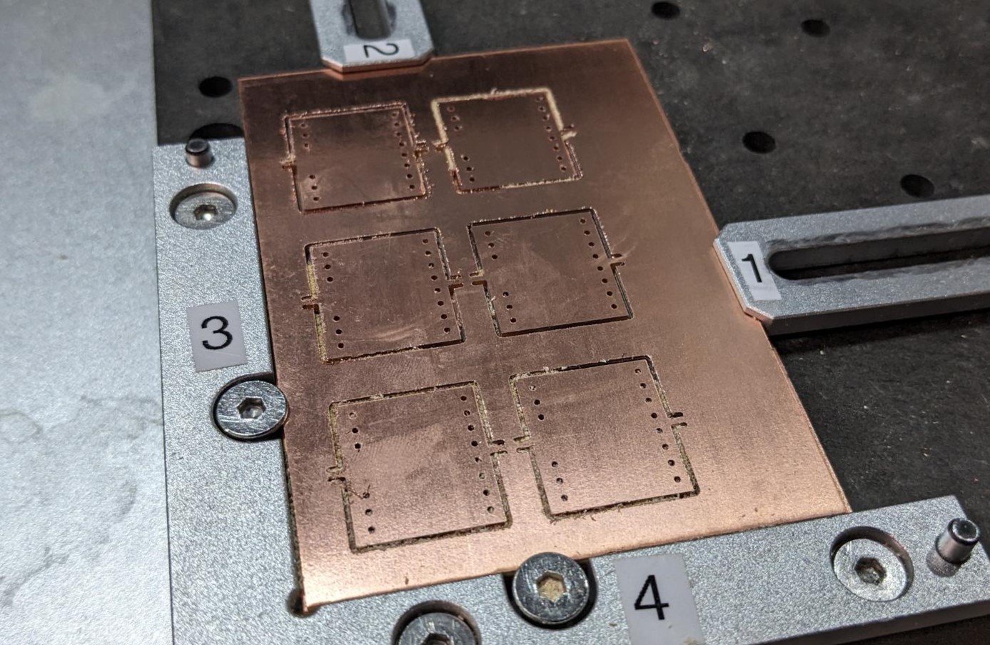
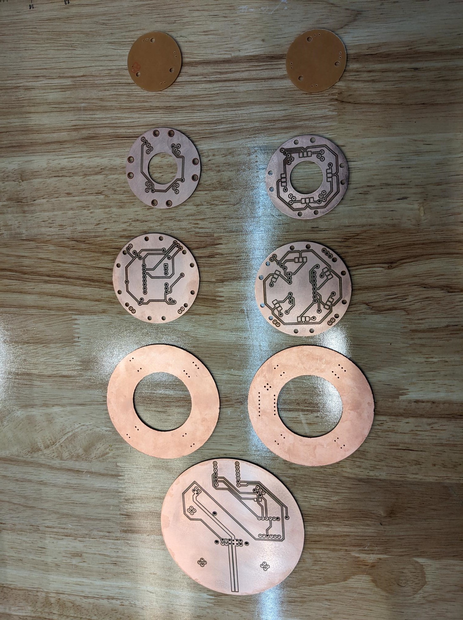
I found it much easier to work in one document where I could see the trace names of the different boards, so to cut and manufacture the boards I had to save the gerber files from a new document. Once I did though, I cut all the front layers of each PCB on the Carvera and then did the backside on the XTool F1 now that I had figured out the alignments. Laser cutting some of the bigger boards did take a while, but overall they worked very well! The front of the boards is on the left and the back is on the right.
We had pre-determined a number of through-holes that would have to connect to both sides of the PCB. So we cut those holes a bit larger on the Carvera to allow for riveting them. Dimitar and Ben had spent some time while I was fabricating the V3 boards on testing the riveting, but they couldn't get it to work cleanly. Oddly enough, I actually had some prior experience riveting hockey skates, so I was able to make use of their efforts in cutting test boards to help them determine the best rivet size for our hole types. I then got to work putting all the rivets in the V3 board and beginning the assembly process. I found soldering the boards to honestly be quite therapeutic since all of the design and prep work had already been completed.
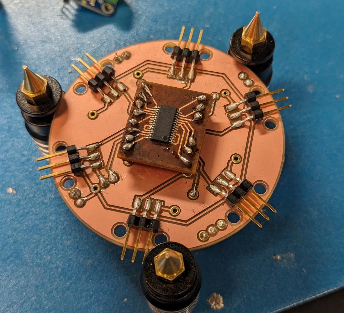
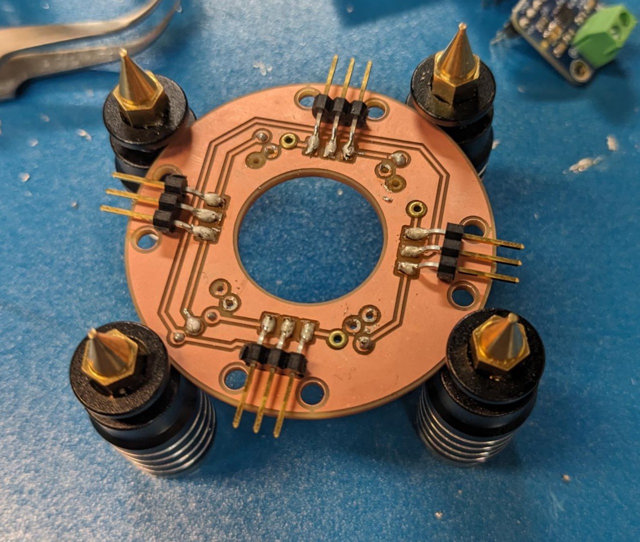
It still took me a few hours to do all of them, and when I stacked them up they were almost perfect. I had to go back and touch up a few pads that did not get connected through the rivet, I needed to increase the spacing since the power board was a lot taller than we were anticipating, and I ended up jumping one of the PWM chip's I2C lines because I could not figure out where the disconnect was. And while I ended up doing this much later in the process, we also made the decision to switch the IMU off of 5V to the 3.3V coming off the XIAO, so I manually cut the power traces to it and used a jumper wire. That being said, the board stack looked insane and really cool at the same time. It is definitely a bit more janky than I would like it to be, but we were also creating a multi-stack PCB out of double sided PCBs which is a challenge in its own right.
I then worked with Matti on the software team to thoroughly test the board before sealing it inside the Neilbot. We made sure each of the servo pins worked which they did, we made sure we could stream IMU data which we could, but we did run into some problems on the speaker. We ultimately found that we don't need to ground the SD pin, after which audio played just fine! After the final debugging we committed to the V3 board and began the process of mounting it inside the frame. Jacqueline did a great job using the laser cutter to create a piece that would align our mounting holes. She also had created a great workflow for assembling the inner triangle for mounting the rack and pinion, followed by the servo and outer triangle to seal the face. I made sure that we were able to route all of the servo connection through slots in the inner frame to the proper connection on the PCB. We just had to be careful with the order that we were attaching the inner and outer triangles to make sure we could access the connections/locations we needed prior to placing the final piece. It took a bit of coordination, but we were able to successfully assemble the Neilbot! We then tested each servo and labeled the face with the corresponding servo number. at this point all servos functioned properly!
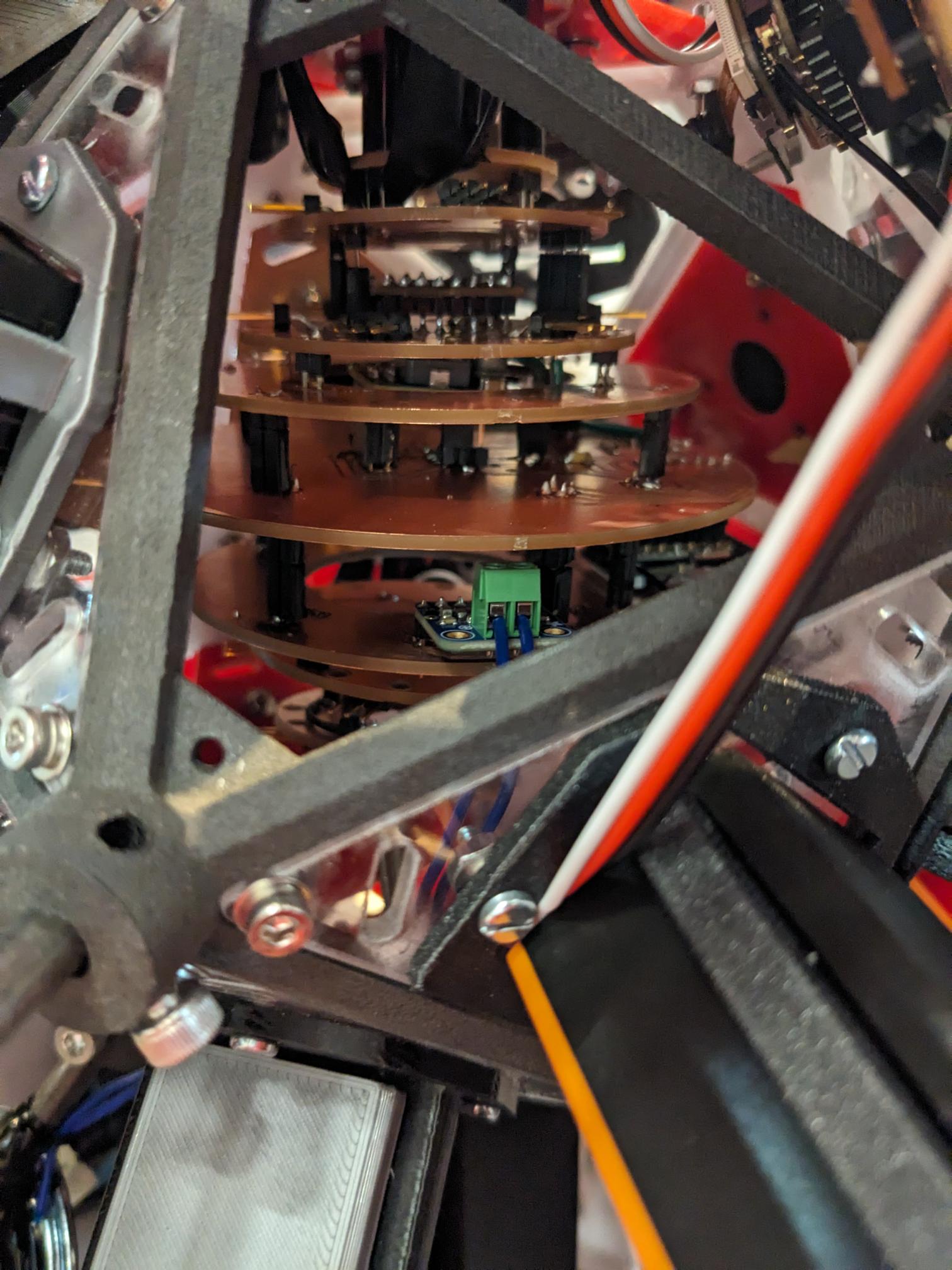
Unfortunately, that is where I called it a night as it was about 3am. The reason that is unfortunate is because during testing at some point the PCB started smoking. Dimitar, Ben, and I have talked about what we think went wrong, and we think we just burned through one of the main power traces. When we extended the servos, the rack and pinion was not rigid enough so the servo gear skipped. That meant the faces were not fully pushed out but the servo was fully rotated, so when the servo then went to retract, it retracted the faces enough for them to be fully seated but then continued to try and drive the servo further. I believe for this test there were three servos actuating at one time, so when they weren't moving and ramped up the current it was enough to fry one of the traces. That meant for our demo we did need to revert to the V2 board as a last minute fix, but we were still able to show the robot off to class which was good!
On a side note, I really do want to try and get the robot working. Or at least create a cool memento from it. So I plan on going back to the KiCAD design for V3 and effectively making a V4. I will make the adjustments we did manually to the IMU supply voltage, I will reset all the through hole sized to not need rivets, and I am going to re-work the power supply lines to hopefully prevent an overcurrent event from melting traces. I will then order a couple of the board from a PCB house and make an actually nice-looking stackup that we can hopefully replace the old PCB with so we can get back to a fully functional Neilbot. Some people on the mechanical side have also expressed interest in strengthening the rack and pinion to prevent slippage which would be great, and there was talk about adding a mechanism to prevent over driving on the servos in case we don't fully extend the faces.
But overall, this was a lot of work to get the Neilbot even to the state it was in. We definitely pulled some really long hours in the shops, but it was also super fun and I am just amazed at what we were able to make in just a single week. I look at this project and think, ok maybe it took a couple of weeks or a month or two, but no it was just one week which is crazy. And I hope that we can get the Neilbot to a state where it can roam the halls of E14/15 and share the wisdom of the Neil-isms we recorded with everyone!