Week 2 - Project Management and Computer-Controlled Cutting
This week we were given an overview of project management styles and design parts for 2D cutting techniques
Assignments:- Read and sign the student agreement (and commit to our repo)
- Work through a git tutorial
- Build a personal site in the class archive describing us and our final project
- Do our lab's safety training
- Cut something on the vinyl cutter
- Characterize laser cutter performance (focus, power, speed, rate, kerf, etc.)
- Design, lasercut, and document a parametric assembly kit accounting for kerf
Cutting on The Vinyl Cutter
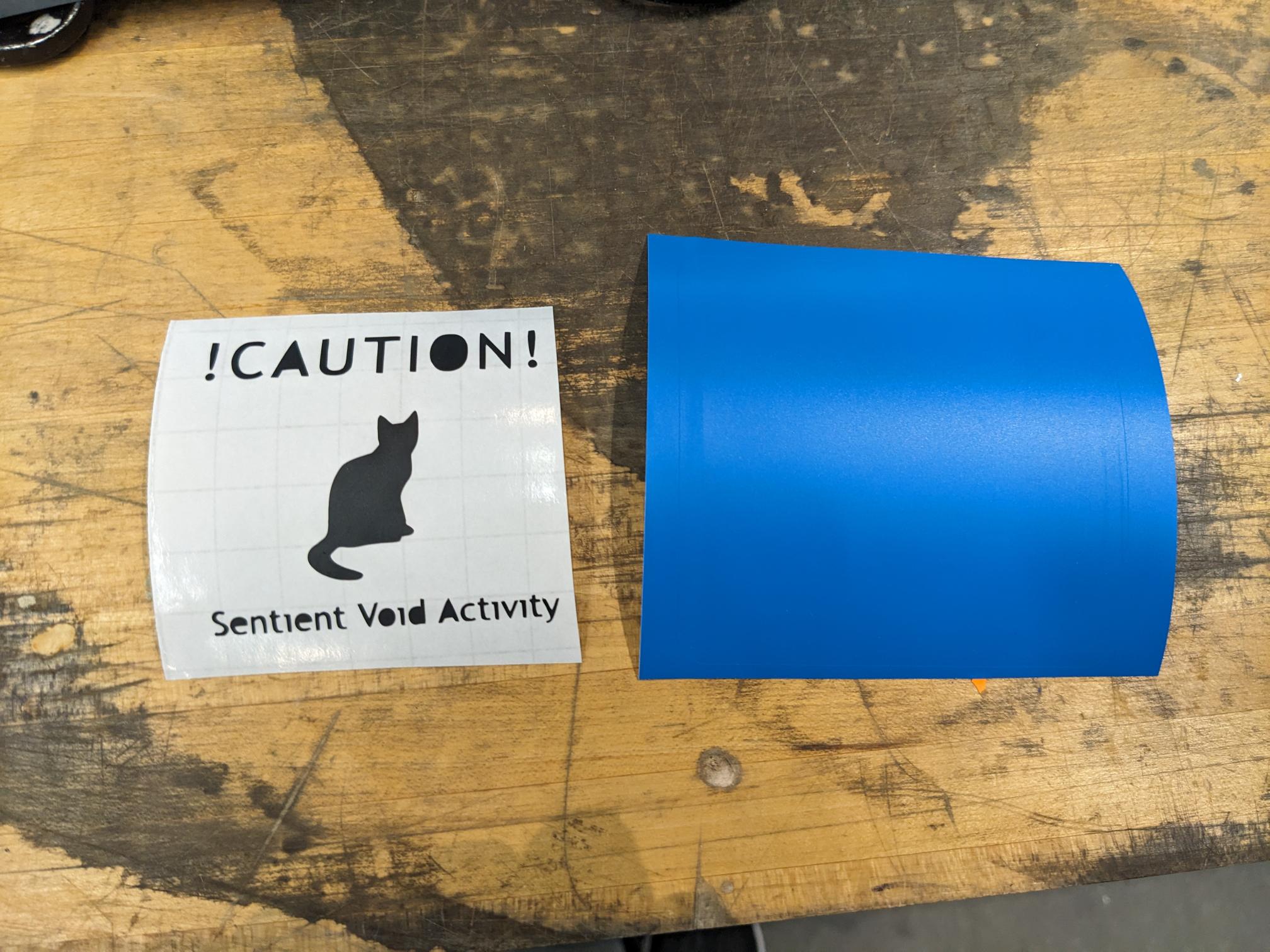
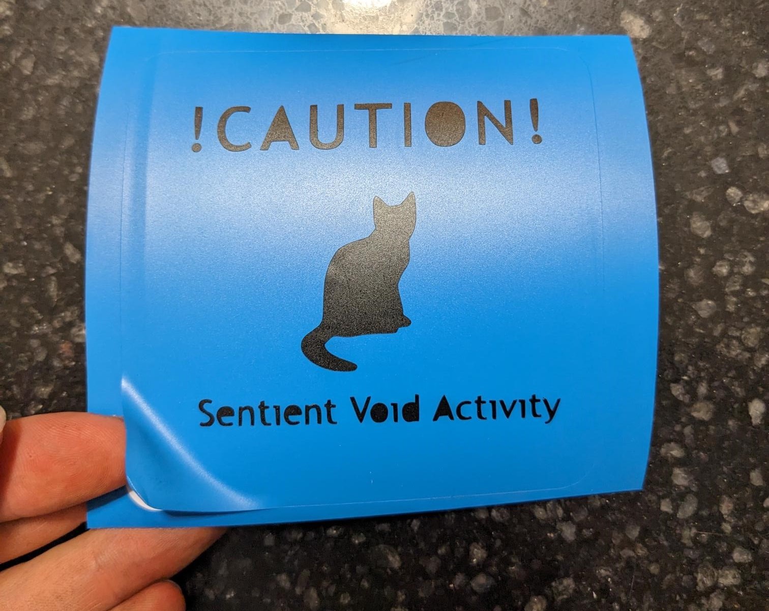
I wanted to make stickers on the Cricut vinyl cutter, and I had a funny idea to make a sticker referencing my black cat. The sketch took a bit of time to make because I had to trace a silhouette, and I ended up changing how I was going to do the background and text once I got some time to play with the tool and figure out how it works. Below the CAD sketch is how the stickers turned out. The blue square is cut out of permanent vinyl, so it is acting as the base layer with a simple square cut around it. The black text and cat image are transferred onto it using the transfer tape and I am surprised at how well it worked (I lost the small dots like I thought I would which is no big deal). I expected I would also have to pick small letters off with tweezers, but it was actually pretty seamless! Also, I couldn't quite find the setting in the Cricut software that would cut out the center of closed letters like O and A, but for my first exposure to a vinyl cutter I really liked using it and I am very happy with the results.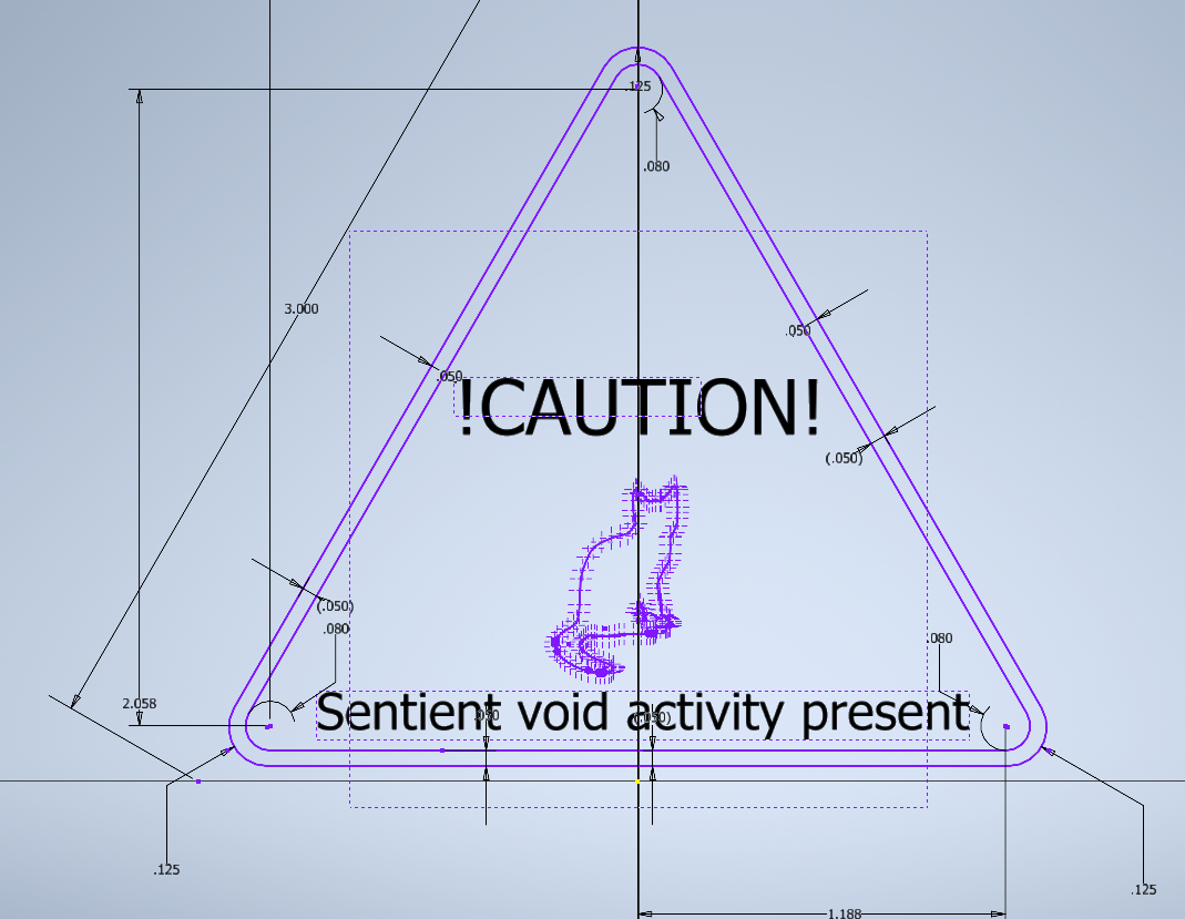
Design files:
Characterizing the Laser Cutter
In order to properly design our parametric assembly kit, we need to measure the laser kerf and how that affects joints. This was done by making 'combs' or squares that had varying slit widths which could be used to find the proper dimensions needed for joints. Our section determined that there was about a .1mm kerf, and the ideal parameters for the XTool were 87% power and 37% speed. We accounted for the kerf in the laser settings and the cuts came out nice and clean (big thanks to Ceci for doing the first pass!).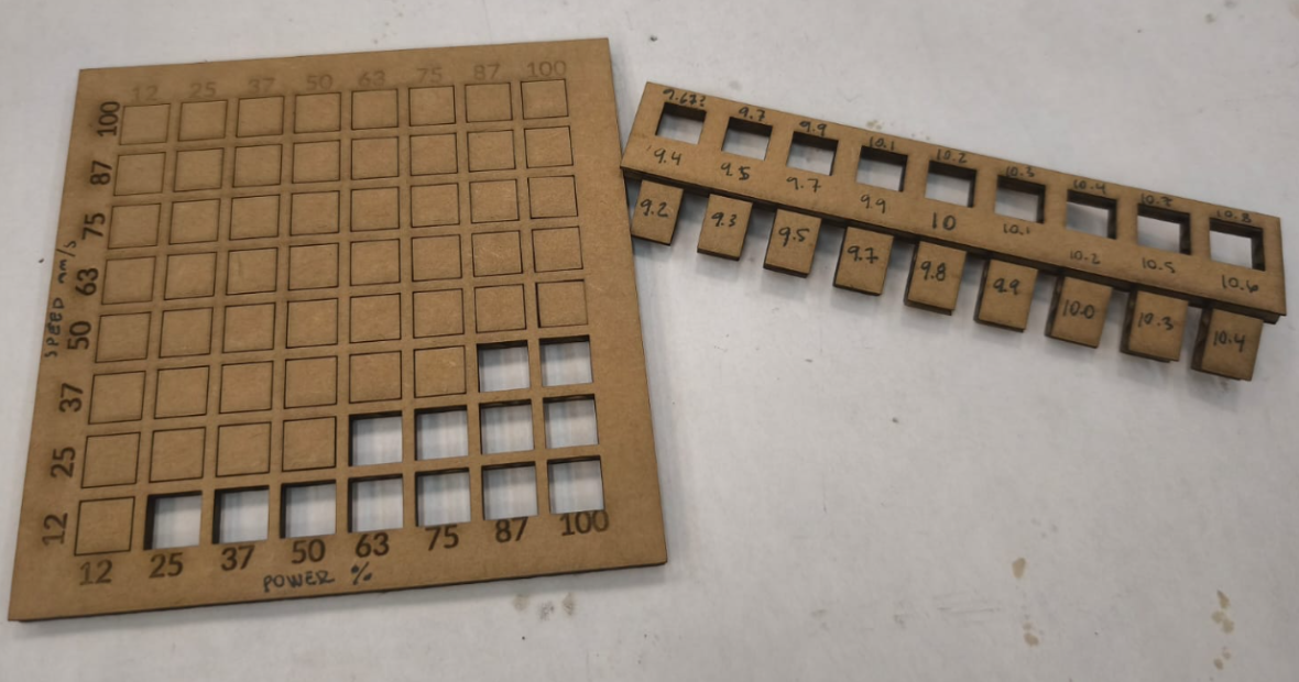
Assembly Kit Cutting on The Laser Cutter
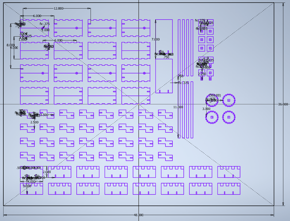
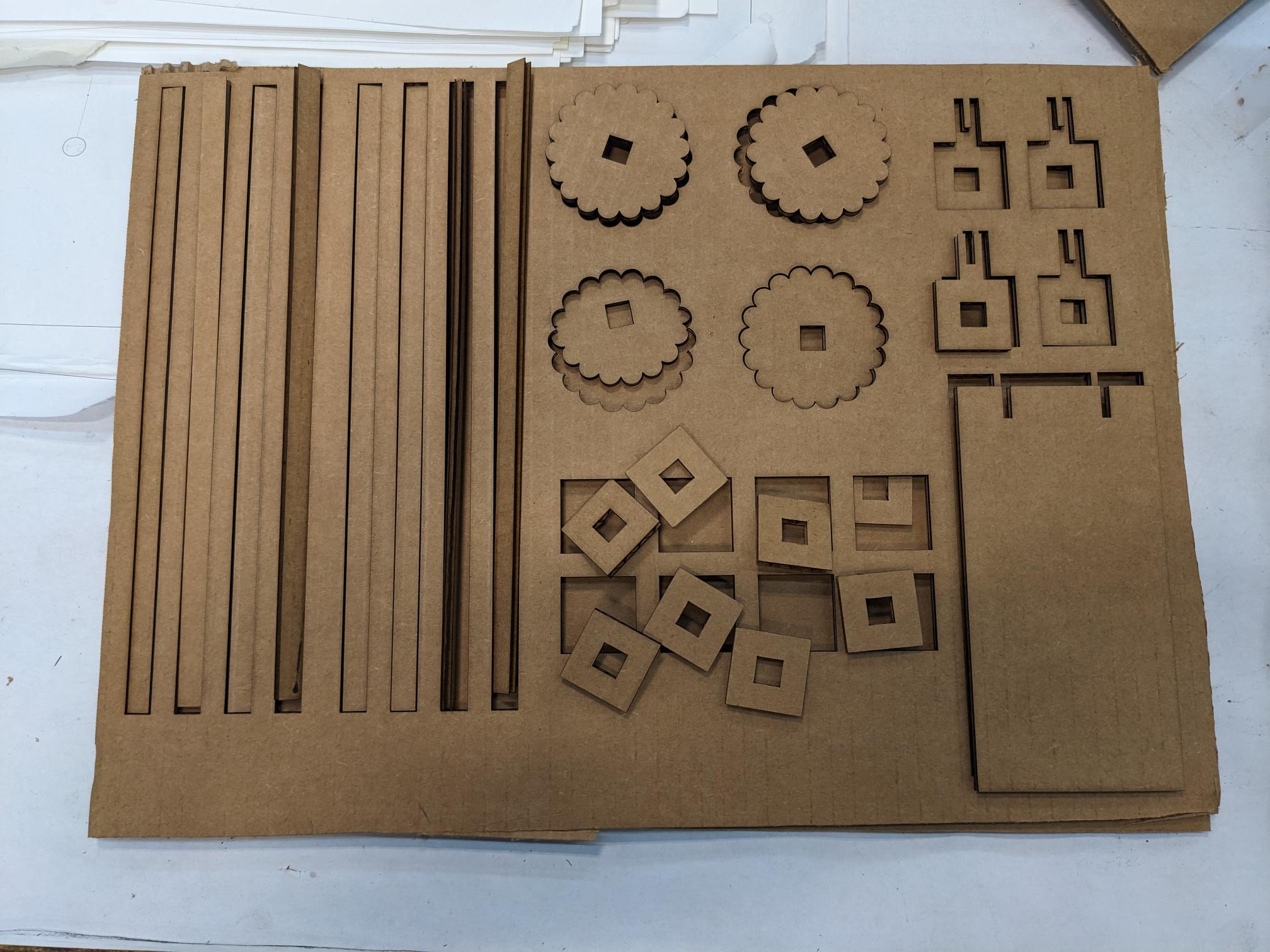
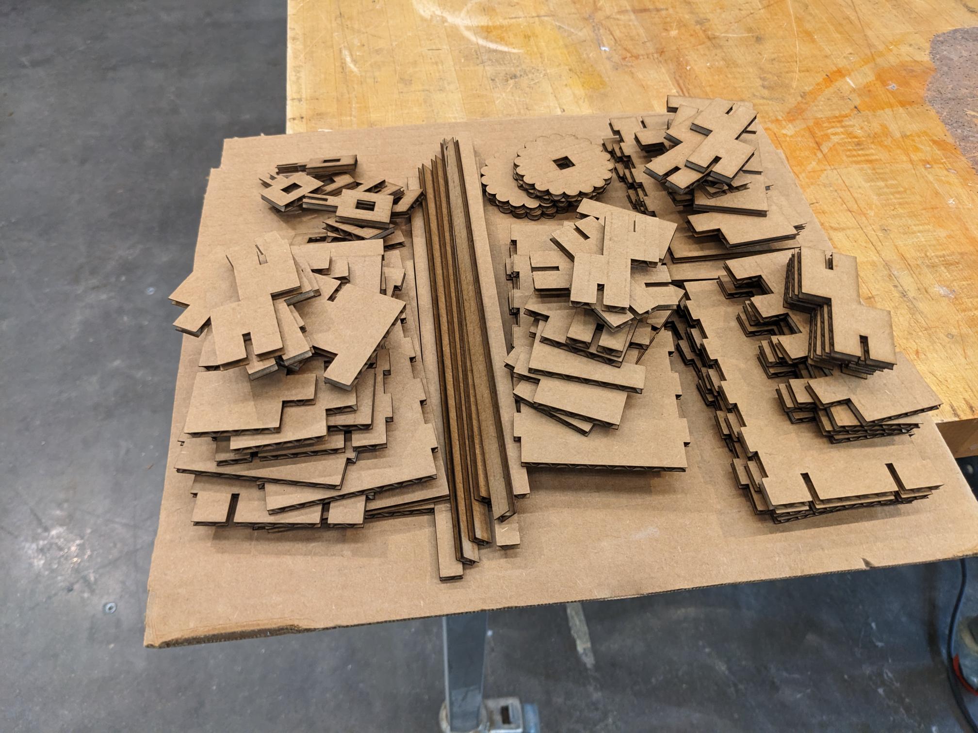
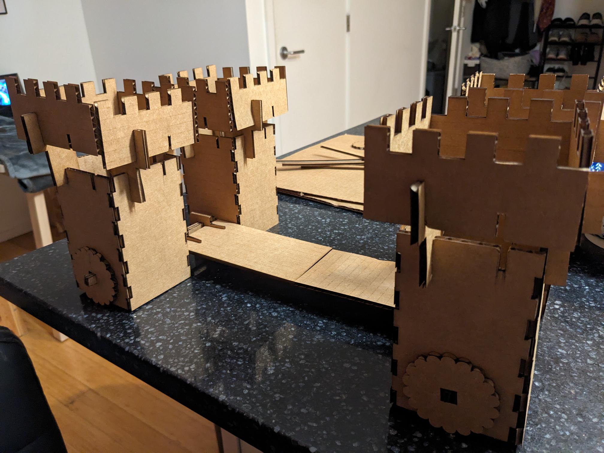
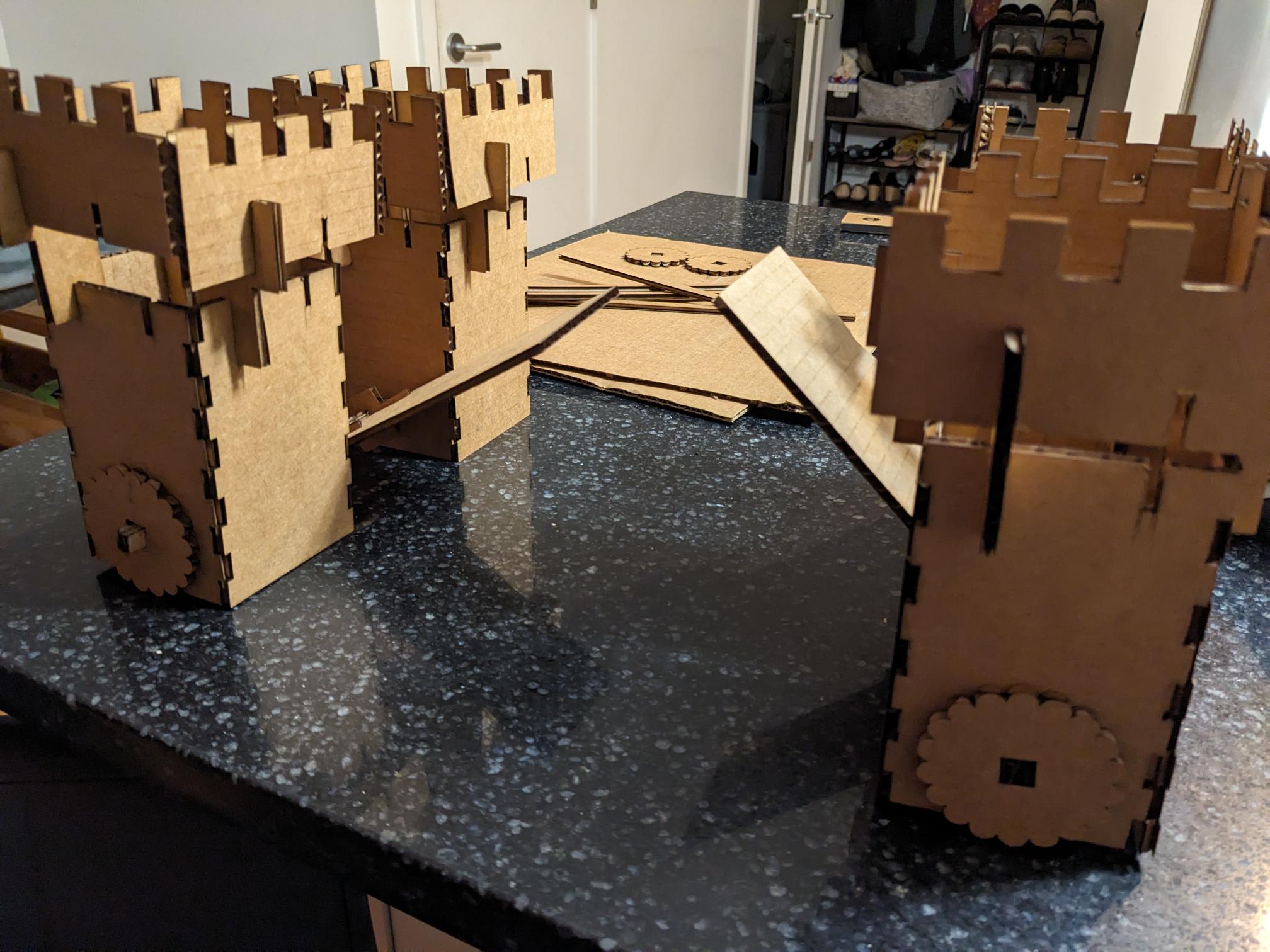
When it comes to actually designing an assembly kit, I came up with the idea to make a bridge that would have the capability of actually raising the bridge portion. The design was simple enough, with 4 columns that would have holes to slot a few pieces of stacked cardboard to act as the axle. There would be a gear to turn to actually raise the bridge, a few simple squares to keep the cardboard axle together, and a joint piece with a square hole to connect the axle to the bridge piece. To make the design a bit more aesthetic I also added a few castle rampart-like pieces to accent the top of the columns. The images below show my initial sketches as well as the sketch I created in CAD before exporting it to a dxf for laser cutting. Ultimately, the idea was executed moderately well but there are a couple of learning points to mention. The most relevant to the general HTMAA population is that I could have designed the corner joints a bit better. Some pieces of cardboard were not perfectly flat which created a bit of bowing that did not let all the corner joints seat well (and they were already thin as it was). In the future it would be much better design wise to have a locking joint of some kind for high aspect ratio parts to prevent bowing from becoming an issue. It would also add to the structural rigidity since my assembled columns/towers were a bit flimsy. Second, and this is something that more so bugs me, the turning of the gear/raising of the bridge is not perfectly smooth. It is a bit sticky but still manageable for now. This likely came down to tolerances/clearance of the circle I cut into the towers for the axle to thread through. But sadly, my biggest goof was that I did not count the right amount of standoffs for the ramparts. I counted in my head that I needed 4 per tower, CADed the correct amount, but when I parsed the CAD file into the individual laser cuts I missed a bunch. Like a lot a bunch... make sure you count the parts you need vs the parts you have! Luckily I was able to get by with a single support holding up the ramparts, but it would have been better if I cut the correct amount.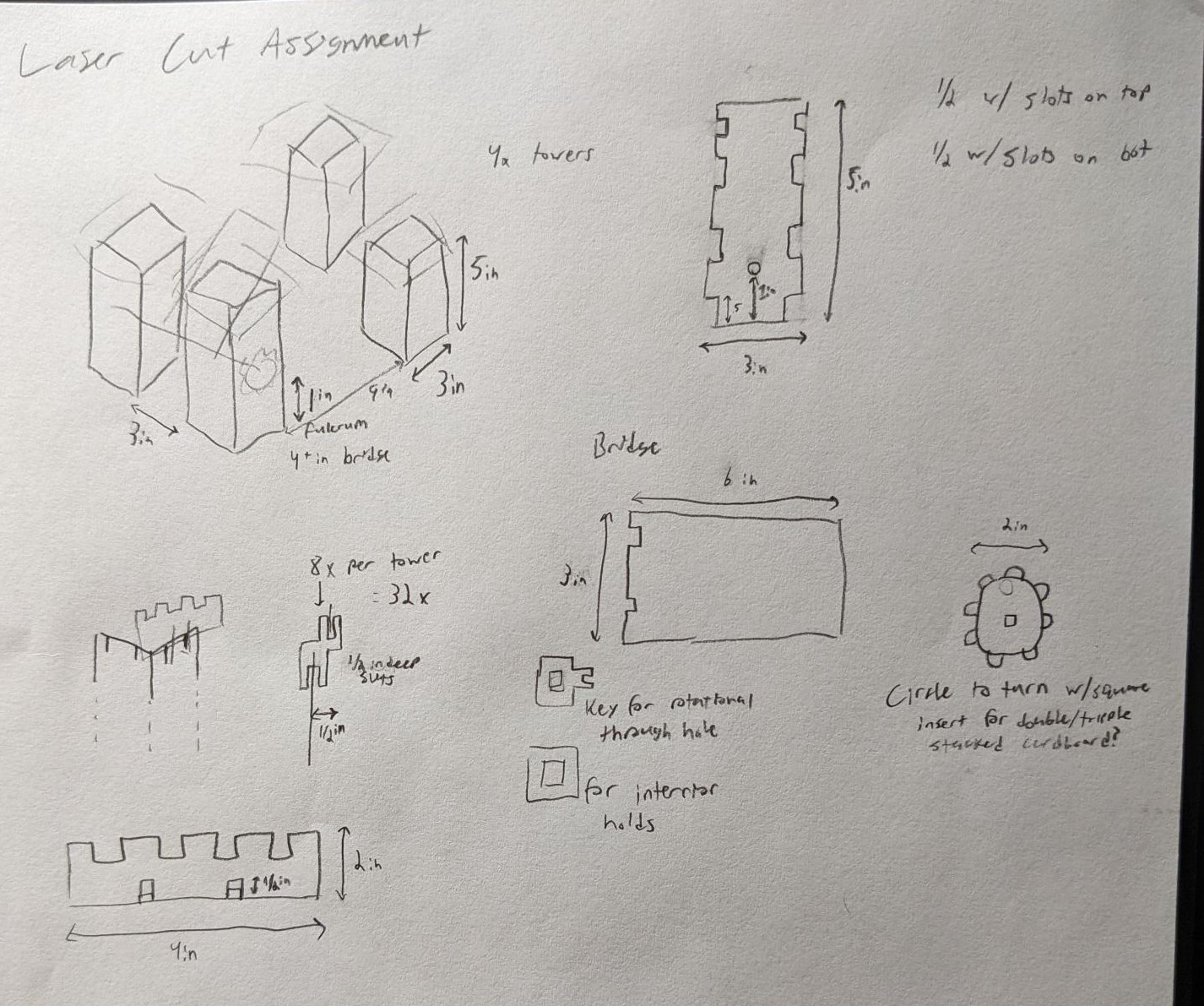
Design files: