Week 3 - Embedded Programming
This week we talked about a number of different microcontroller architectures, highlighting the ones we would have available for class. We also discussed the different blocks they are built with, performance, and cost. Some details on programming the microcontrollers as well as the languages they support were presented with example programs and their effects.
Assignments:- Compare workflows for different architectures (group)
- Browse through a microcontroller data sheet
- Program an embedded system using a microcontroller to interact and communicate
- Extra credit: try different languages and/or development environments
Comparing Different Microcontroller Architectures
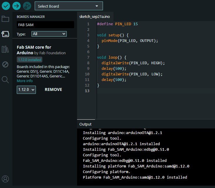
During the lecture portion of class, we talked about a couple of different microcontrollers we would have access to. We primarily talked about the RP2040 and SAMDs, but ESPs and ATtinys are also listed in the course material. Most of the microcontrollers I worked with previously had Arduino boards, which as we learned can mean a lot of different things depending on the context. In my case, my Arduino experience refers to completed boards (like the uno and nano), the coding language, and the IDE. Because of this familiarity this is the toolchain I used for these assignments. I was not present at the discussion, but Ben, Jaqueline, and Matti put together a great document on our sections site discussing their experience (big thanks!). I added some notes of my own in another pdf and hopefully more will be added over time. Their group had a broader range of experience than myself, but it seems like there was similar sentiment around Arduino. It's very easy to use and welcoming to beginners, which is the main attraction of the platform. Branching out more, the teensy microcontroller had some issues with timing when running through Micropython, and the ESP32 is trickier to set up and get running in the first place. That being said, Python is a very easy language to use, more so than C++/Arduino code in my opinion. Depending on the amount of effort a user is willing to put in to get up and running there is no reason that a more setup-intensive platform couldn't be used if that is the preferred method to work with.Back to my workflow. The first step was to configure the IDE to be able to find the microcontroller. In the lab section I made a board using the SAMD21, so that determined the architecture I was working with. Quentin put together a great guide with examples and tutorials here, and he also helped me during the lab session to upload the bootloader. That meant I only had to set up my IDE and begin uploading code. Below is a screenshot of the SAMD core installation and the board with the "Hello World" sketch uploaded to it.
Programming a Microcontroller
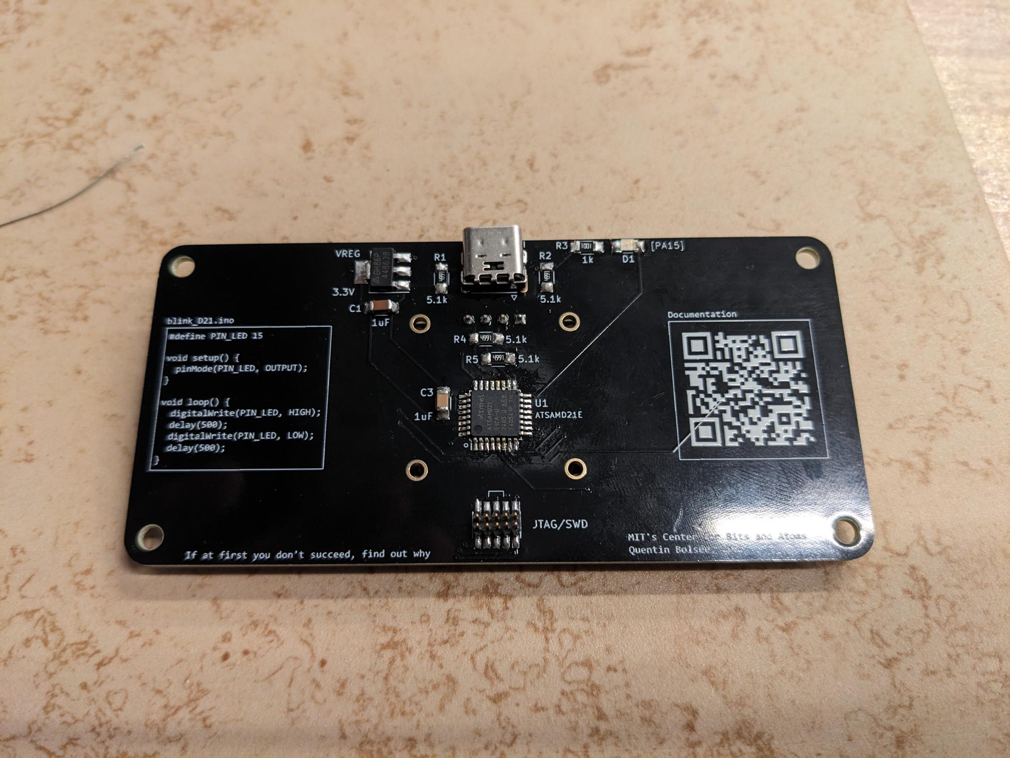
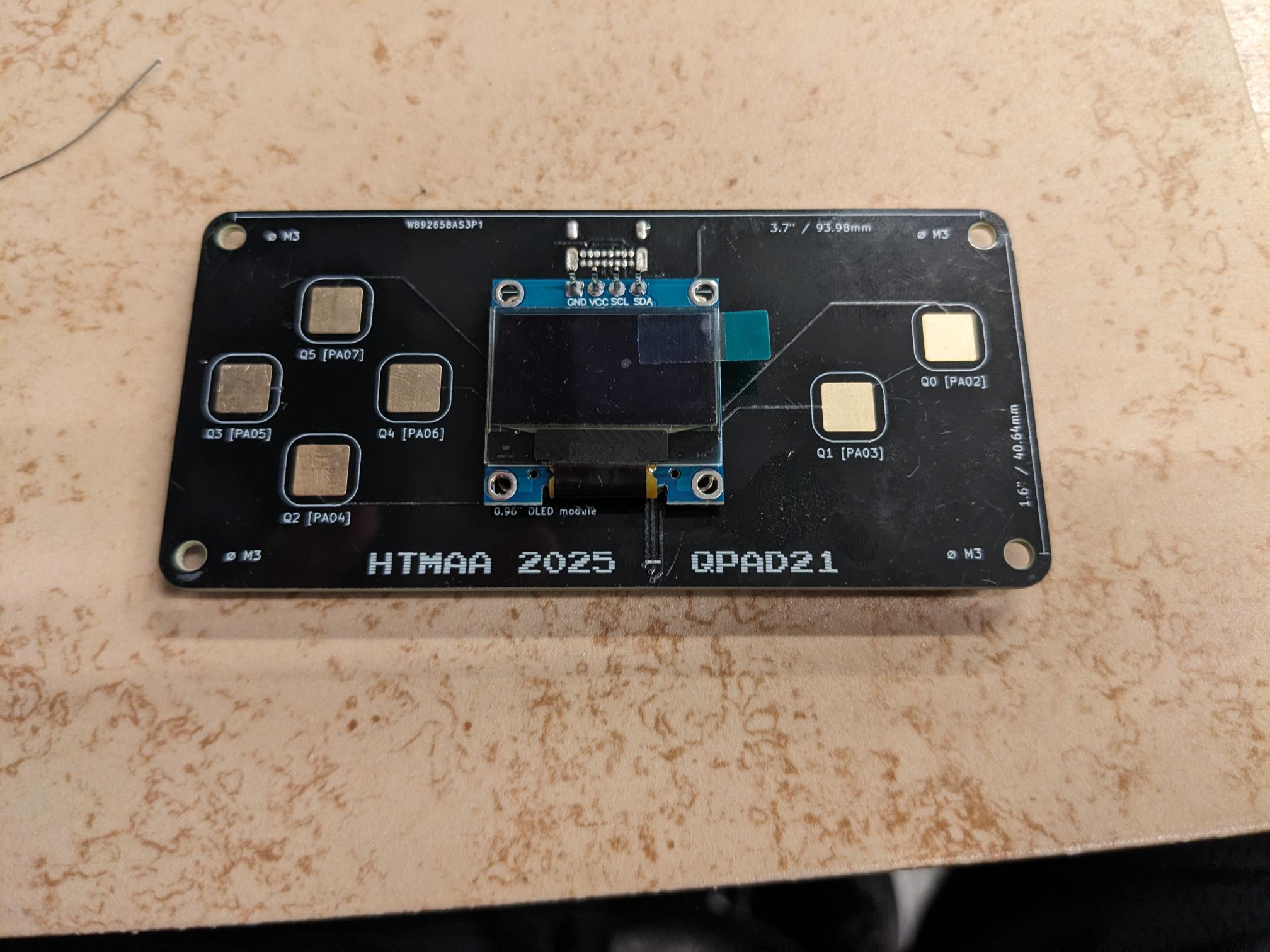
As mentioned in the previous section, we had a lab session the consisted of soldering together a game pad with a microcontroller, an LED indicator, a small screen, and in my case a USB-C port. For the most part I didn't have much trouble since I have a lot of experience soldering and the components were on the larger side. However, I have not used solder flux too often and I did create a few bridges when mounting the SAMD21. These were quite annoying to fix and I was hoping the shorted pins were not connected, but after consulting the data sheet I found they were significant. But, with enough patience and reworking, I was able to fix all of my shorts, and everything worked as intended. The initial image below shows my board with only a few components soldered, followed by pictures of the front and back of the completed board.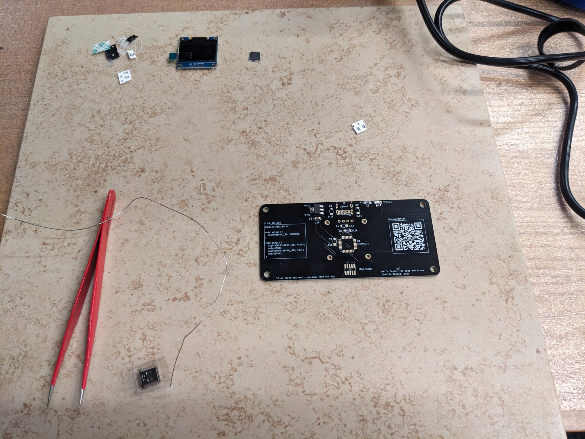
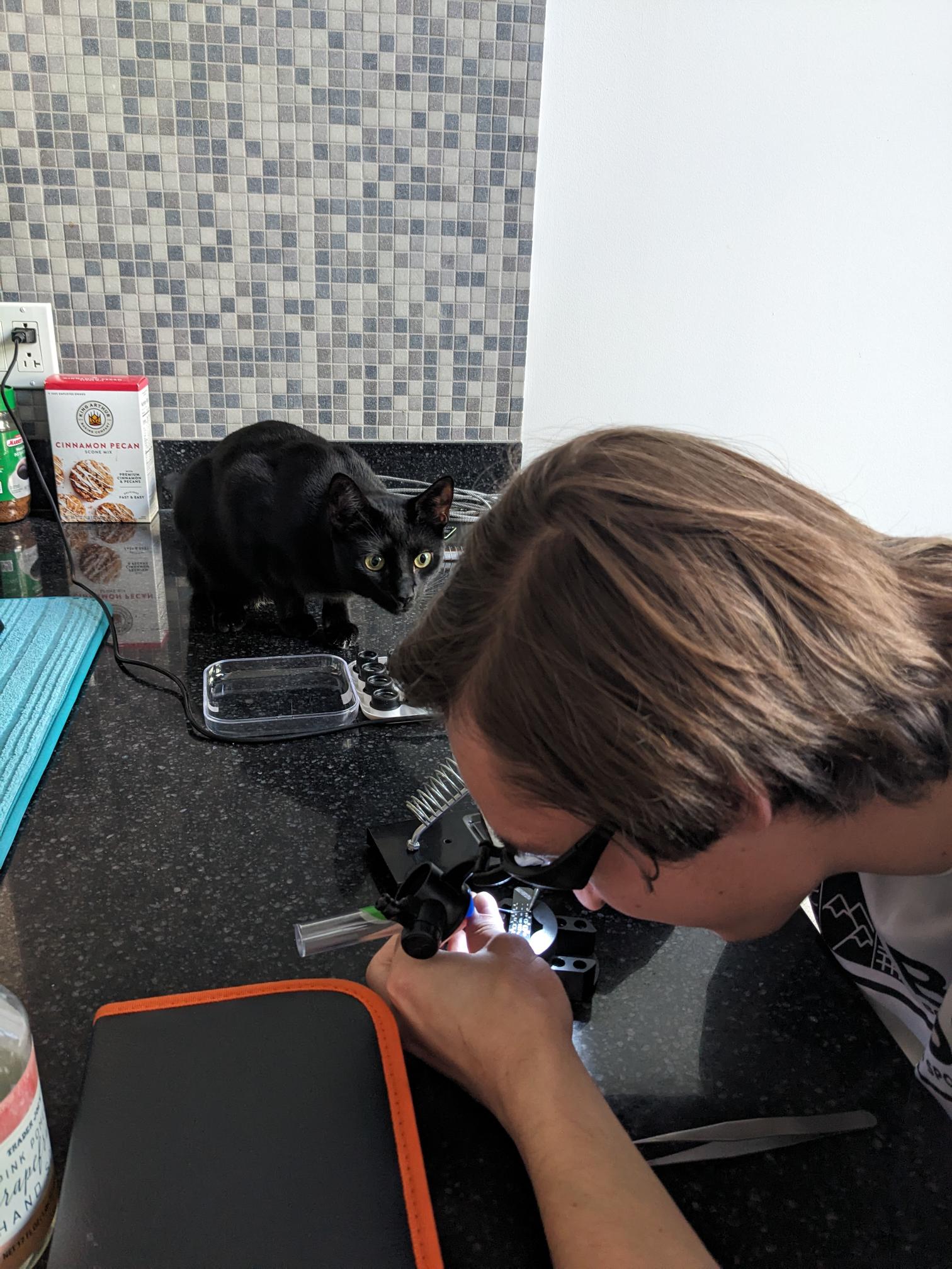
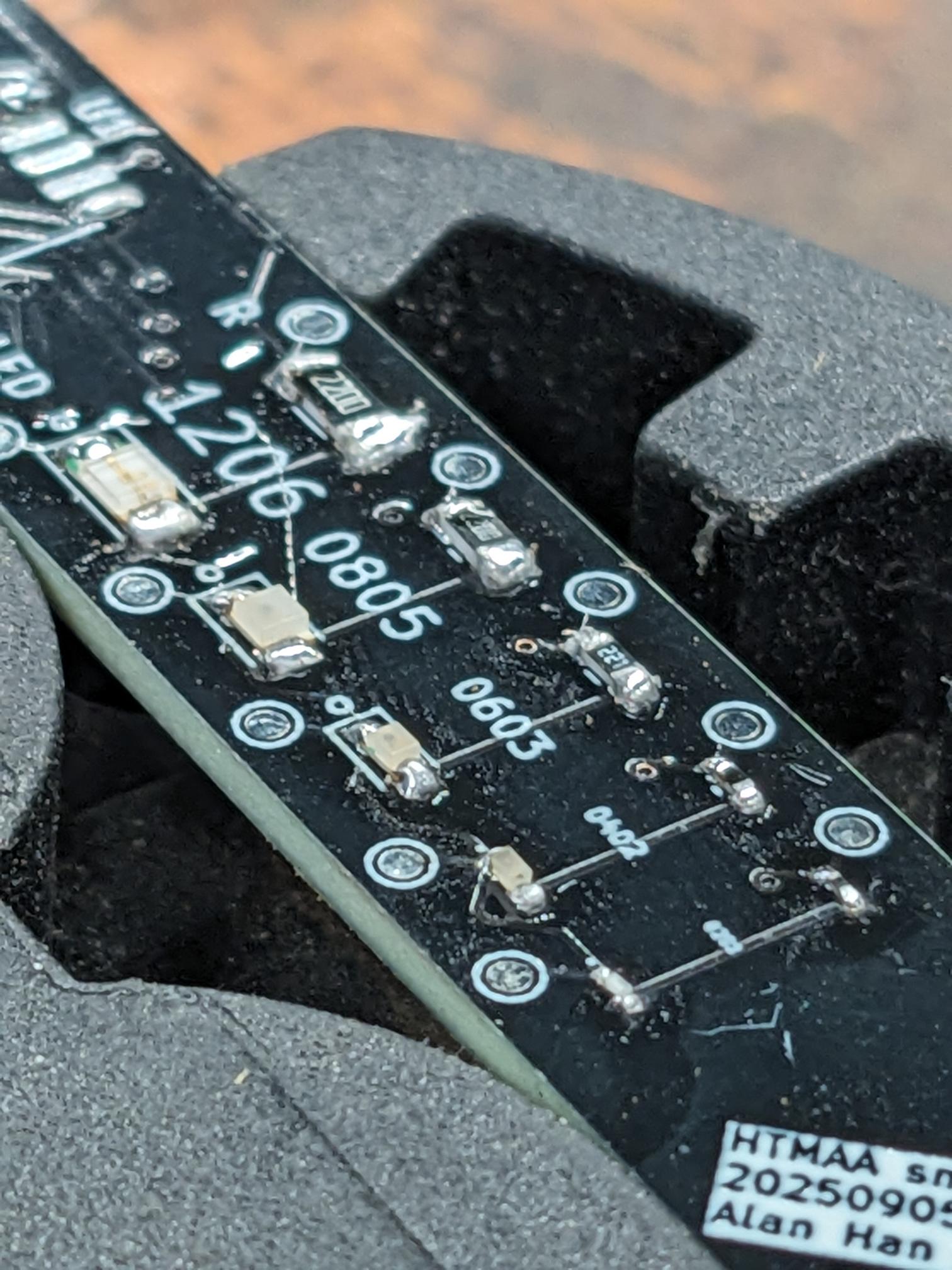
I didn't have enough time to work on the challenge board during the lab session, but I still wanted to give it a shot because I had some basic equipment at my apartment. The challenge board was hard because the components started at a larger form factor (1206s) but scaled all the way down to super tiny LEDs and resistors (0201s). I didn't have a microscope to assist with the smallest sizes, but I did have loops and moral support from Raven so I think I was able to do really well. Sadly, there were not microcontrollers available for this during the lab session so I am unable to actually test my board at the moment, but I feel like I put together a good attempt at doing this challenge board by hand.
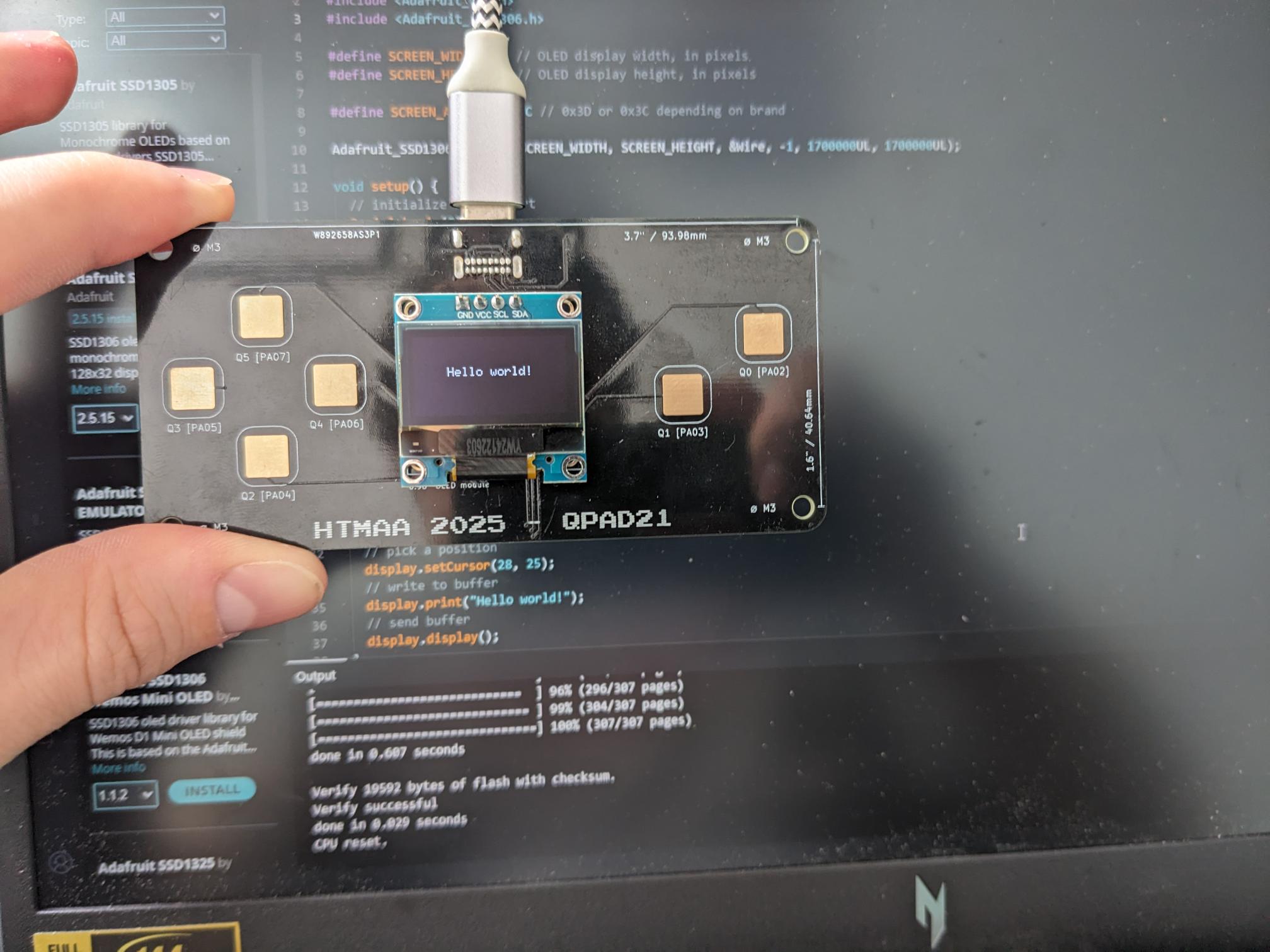
Once the main board was completed, I uploaded the bootloader and set up my IDE. These steps were covered in the above section discussing microcontroller workflows. I was able to successfully run all the test code provided by Quentin, and a video of the button responses is seen at the end of this section. While this sketch did demonstrate taking input into the microcontroller and communicating those inputs back to a monitor/plotter, to satisfy the assignment I decided to modify the examples and create a sketch sketch. I tied the d-pad buttons to the display coordinate system to allow the user to move the current location of the cursor. I then used the Q0 and Q1 to act as placement and removal of pixels by either drawing the pixel in white or in black. I did have to guess and check the movement directions since the orientation of the screen is not matched to what the user would anticipate based on how they would hold the board, but that was a very simple fix. The code I used is linked below the videos!