Week 5 - Electronics Design
This week we were given an introduction to circuits and circuit components so that we can consider how they would come together on a PCB. We talked about how circuits are designed and associated software used for checking design and electrical rules, along with additional software that can be used to simulate the circuits.
Assignments:- Use the lab test equipment to observe the operation of a microcontroller as a group
- Design and simulate an embedded microcontroller system using parts from the class inventory (check design rules for fabrication as well)
- Extra credit: Try another design workflow
- Extra credit: Design a case
Testing a Microcontroller
There were two sessions that were scheduled to go over different types of electrical test equipment. These were multimeters, oscilloscopes, logic analyzers (mixed signal and digital), and power supplies. I was unable to make either of these sessions due to travel and work, but Eitan did an amazing job taking notes during the first group session. On Monday I also caught up with Jaqueline and Matti who had gone to the second session earlier that day and asked about what they covered. Since I have had a lot of experience with test equipment, I did not have a problem understanding what they were shown. Our group site can be found here.
Designing and Simulating an Embedded System
For this assignment I thought it would be fun to create a handheld version of the mastermind 'codebreaking' game. For those who are not aware of this game, the simplified version that I decided to implement consists of a colored 4-LED sequence that is randomly generated and the player doesn't know it. The player then has to guess what the sequence is, and for each round of guessing they receive feedback based on the number of correct colors but wrong positions and the number of correct colors that are in the right place. The difficulty of the game can be adjusted by changing the number of colors that the LEDs can be. For example, an easy game may only have 4 possible colors for each position, but a difficult game could have as many as 8.To implement this game on a PCB, I anticipated that I would need 4 RGB LEDs that will act as the player entered guess. The RGB LEDs listed on the inventory page are each 4 terminal devices with an input for each color. That means I will need 12 output pins on the microcontroller to handle the guess LEDs. I had planned on using a surface mount SAMD21, so that that limits me to 4 other digital pins and the 6 analog pins remaining. Of those pins I will need 4 analog pins to make touch pads, so I have 2 analog pins and 4 digital pins remaining. It would have been great if the LEDs on the inventory list had a low enough forward voltage that I could use the analog pins to selectively power a certain number of them, but since the Vf is 2V I won't have enough power coming off the microcontroller to make that work. Instead, I will use two of the remaining digital outputs to blink a green and orange LED which will each represent completely correct and partially correct guesses respectively. I will tie the last two digital pins to two red LEDs that will allow the player to select a difficulty at the beginning of the game.
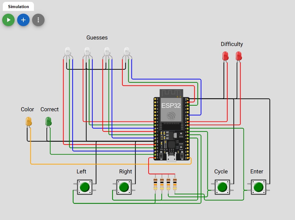
I chose to complete this assignment by using the Autodesk Fusison as the EDA tool and Wokwi as the simulation platform. I figured Wokwi would be a bit better for simulation as I am going to be writing a lot of code for this assignment and I want to make sure that works in conjunction with how the board would be laid out in Fusion. That being said, Wokwi did not have a SAMD21 available for simulation, but since I planned on writing the code in Arduino in the first place I figured I could simulate the code using a different microcontroller as long as it had enough pins. I needed 16 digital pins to handle the LEDs and 4 to handle the inputs, so the standard ESP32 device had enough inputs for me to use. I also used simple push buttons in the simulation rather than touch pads as inputs due to what was available, but I will just have to change the code to handle the difference. I also realized after the fact that I did not include resistors on the LEDs in Wokwi, but 1kOhm resistors have been implemented on the board in Fusion to handle the current through the LEDs. The design of the circuit in Wokwi as well as a video of playing the game can be seen below.
I think my implementation is solid, but I had a lot of trouble figuring out the code to count guesses of the correct color but the wrong location. I had a bunch of issues with certain locations be double counted, but I eventually figured out I was counting from the right answer side of things rather than the guess side. Changing that around got me to a good spot, and I did skip the rest of the code that counts locations if the guess matched the answer first which really helped eliminate the final instances of double counting. I do wish that I had more space for extra LEDs, because blinking the orange and green as guess indicators take up the microcontrollers actions and the user cannot activate any buttons while this is going. I had to balance how frequently the feedback was given vs how much time the user had to change the guess in order to make it feel convenient to play. This version is also a bit hard because you can't see the past guesses which really helps inform future decision, but it is still solvable and fun to play.
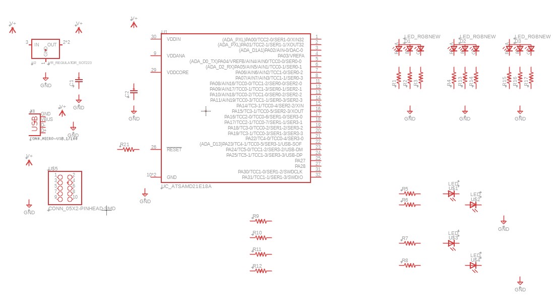
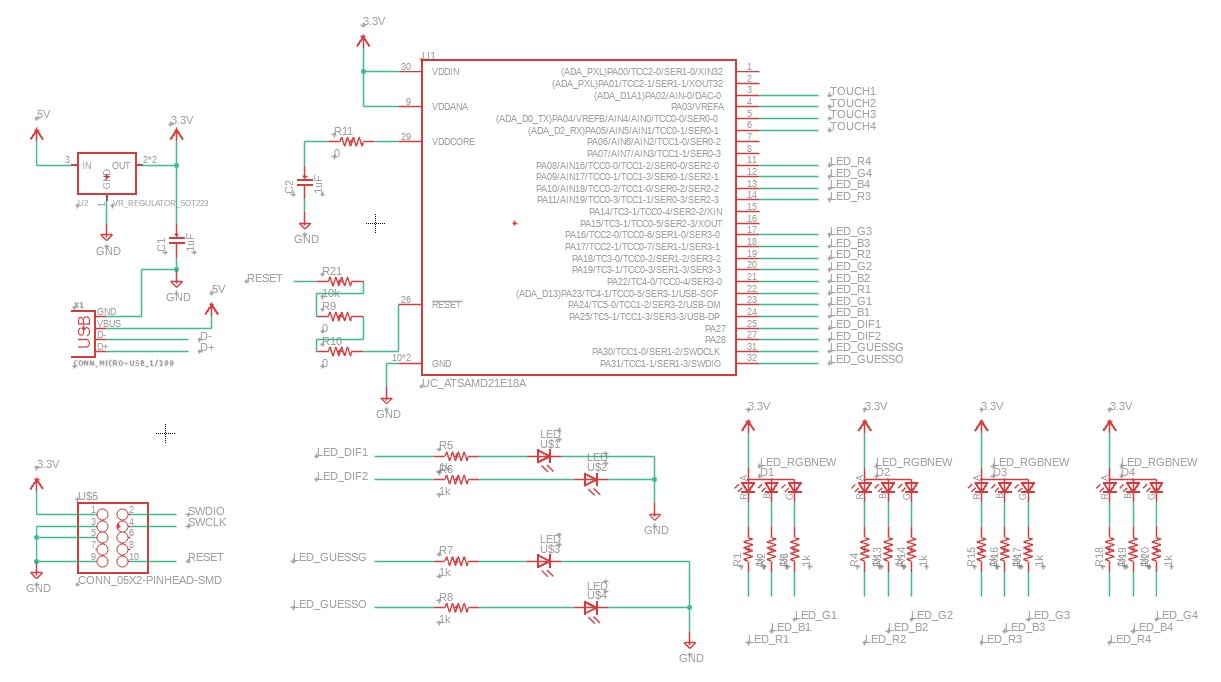
When it comes to making a PCB on Fusion, I had used Fusion before but never for electronics. I followed the menus to get to the electronics design portion and started dragging parts from the FAB library into the schematic view. After playing around with some parts I found that it was also populating a PCB document with the parts I was placing. I would then just have to drag them into place after I was done setting up my schematic which I thought was pretty cool. Aside from the parts I knew I needed from my Wokwi simulation, I also added supporting hardware like the 3.3V regulator, micro-USB connector, and programming pins based on inspiration from Quentin's Q-pad board. Once everything was placed, I wasn't entirely sure the best way to tie ports together, but Anthony put together a great tutorial video here that I used to fill in the gaps of just playing around in Fusion. With his video, I completed the schematic design and cleaned up the file to be easy to follow. There are a few additional 0 Ohm resistors that were added to the final design as well, these came in during the PCB layout portion and will be discussed in the following paragraph. The RGB LEDs in the shop also have a common anode for the three color channels. In the simulation I used common cathode LEDs, so I will have to remember to switch the HIGH and LOW states for actual board.
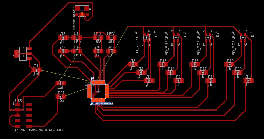
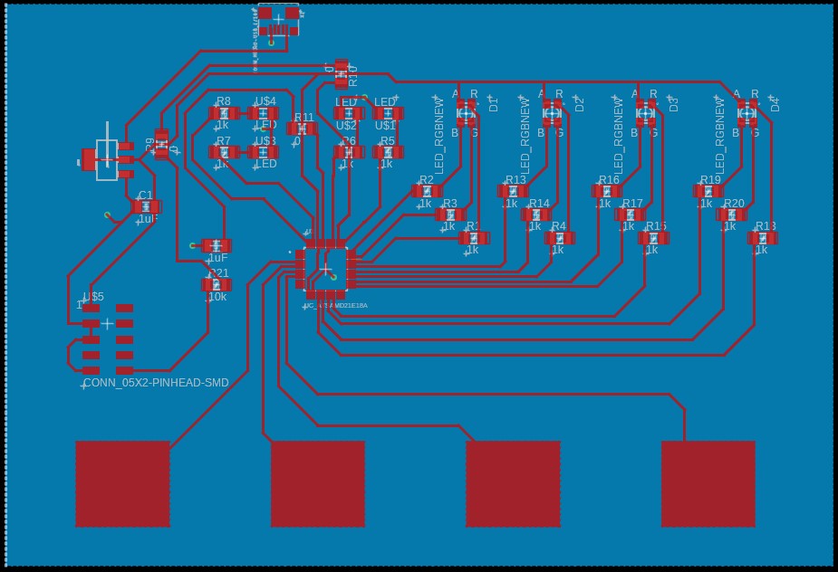
For the most part creating the PCB layout followed the same strategy as the circuit schematic, only this time there were 'air wires' that helped inform where the connections needed to go. Since I did the Wokwi simulation, I had a good visual of where components should be roughly placed to prevent traces from crossing. This was immensely helpful, and I specifically named the nets in the circuit diagram to account for the PCB placement. After I did the first round of placement and connections (left image), I was left with a few traces that were unable to reach their destination without crossing over another trace. Alfonso gave me some really good pointers that let me complete my PCB layout nicely. At first I was planning on routing the remaining traces on the backside of the PCB, but he recommended to instead turn it into a ground plane and route all the GND signals to it which helped greatly. I then had 2 remaining signals that he suggested I could route through 0 Ohm resistors to act as jumpers over traces. These additional tips helped me complete the PCB board and create the picture on the right. I then had to make sure everything passed DRC checks though...
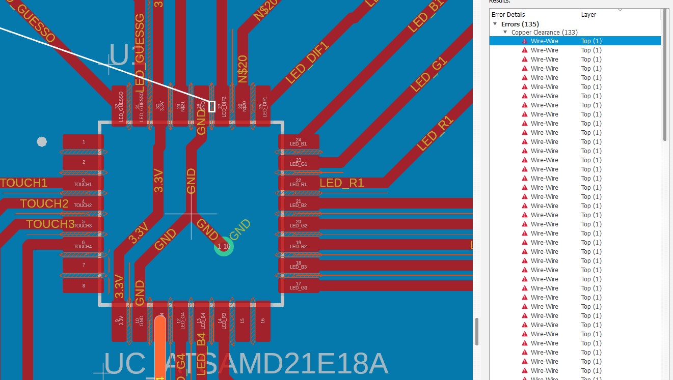
Taking a look at the DRC errors, I had 135 errors to look through. At first I was a bit worried, and I found that the first few of them were handled by making sure a trace was actually connected to a pad. Visually it was, but there was a very small air wire left saying that there was a missing connection. After fixing those, I was left with 134 errors. After looking through them, they were all related to the spacing of the surface mount SAMD21 and the micro-USB port. I had adjusted the DRC rule to look for spacing of 16mil based on Anthony's video, but there is no way to get around this sizing issue because of the surface mount nature. In this case, I approved these DRC errors and tentatively I would say my PCB is all set to go.