Introduction
This page shows the progress on the frame designing of Richard Liu's final project.
Progress
Designing of the Gimbal
Since I have had some experience in using Solidworks, I decided to use OnShape to design most of my projects in this class.
My gimbal must have three degrees of freedom to perfectly cancel any arbitrary vibrations resulted from motion or other effect. Therefore, the gimbal should have three arms, which should be guided by three stepper motors. Besides, It should also have a handle for me to install battery and main controlling board.
Handle
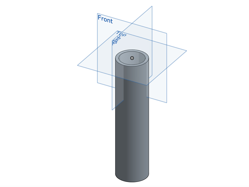
The handle is designed to be a hollow cylinder. Inside the handle, there will be a small battry to power the whole gimbal. Then on top of the battery, there will be space left for the main controller to do all the PID calculations, as well as give instructions to the motors and heater.
The first stepper motor will be placed on the top of the handle, with first arm installed above that.
Arms
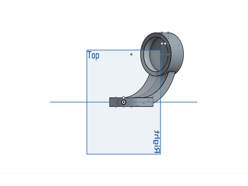
This is the 1st version of the arm. Basically, the arms are designed to be curved sticks with one end screwed onto the motor on previous stage. The other end of the arm will hold a stepper motor.
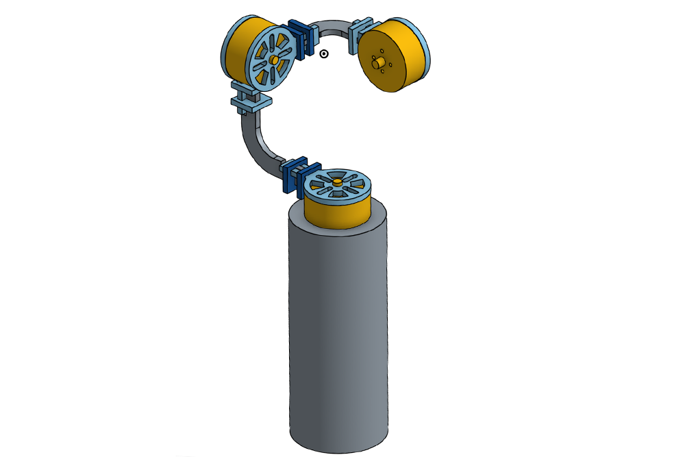
Assembled Gimbal
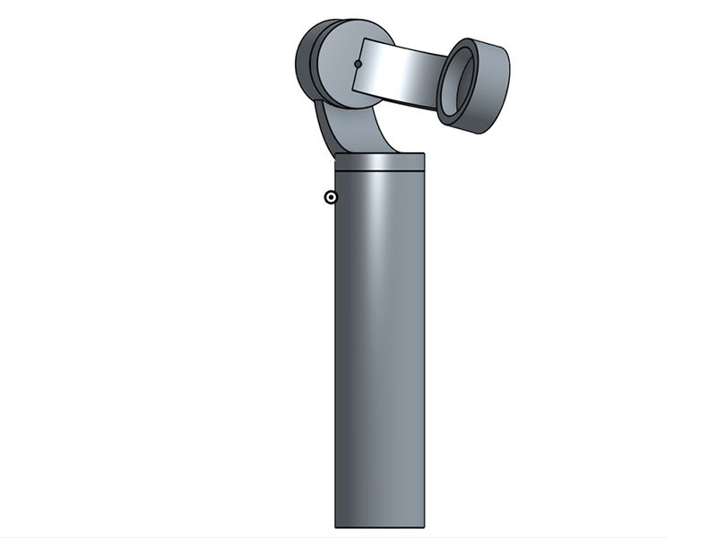
This is the 3D view of the assembled gimbal.
2nd design of the arm and selection of materials
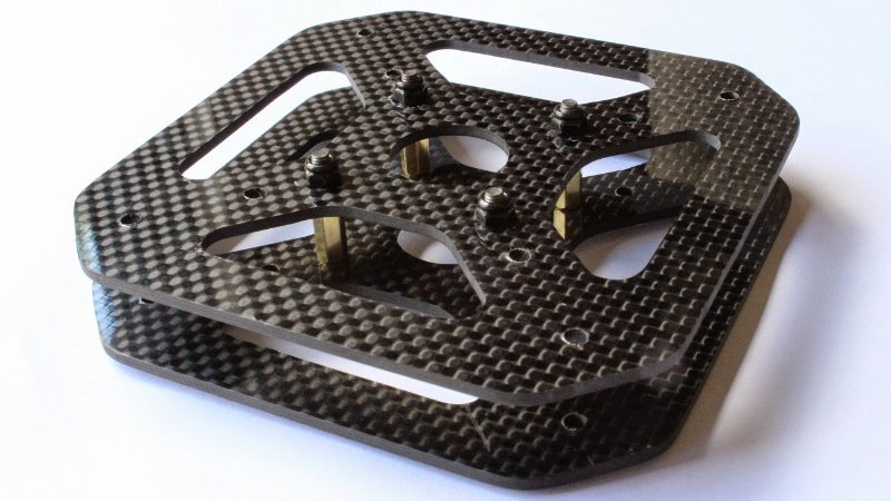
In order to make the gimbal lightweight and robust at the same time, I decide to use a special material for the arms and motor holders -- carbon fibers. I have seen a lot of people use carbon fibers to fabricate their drones and bikes, because carbon fiber is the ideal material that can be strong and lightweight at the same time.
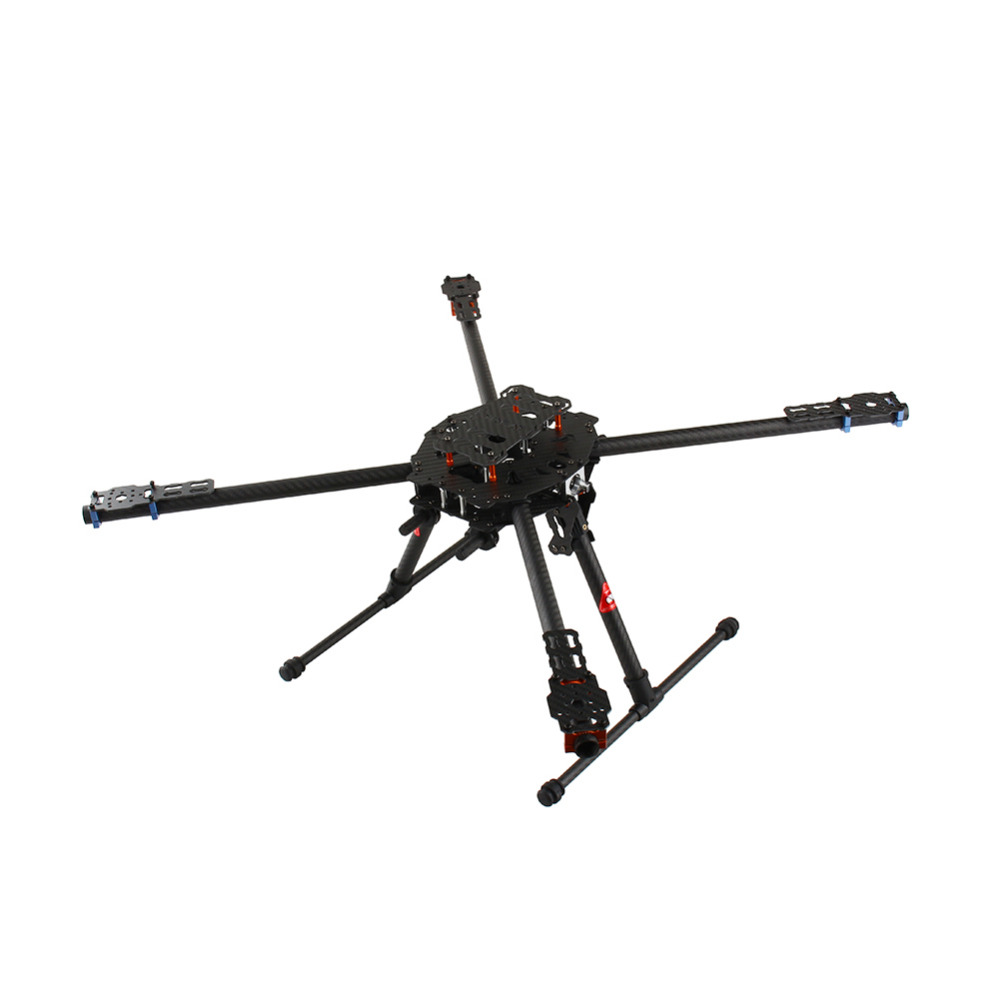
Image of a drone frame made of carbon fiber (the picture was adapted from aliexpress.com).
However, carbon fiber is not easy to machine. Instead, they often come in a stack of thin plate or straight rod. Therefore, if I want to make the arms of my gimbal out of carbon fiber plate, I must come up with a different design.
By looking at carbon fibers from online stores, I found the one with 0.06 inches of thickness could work for my project. Here is my new design for using carbon fiber sheet to construct a gimbal:
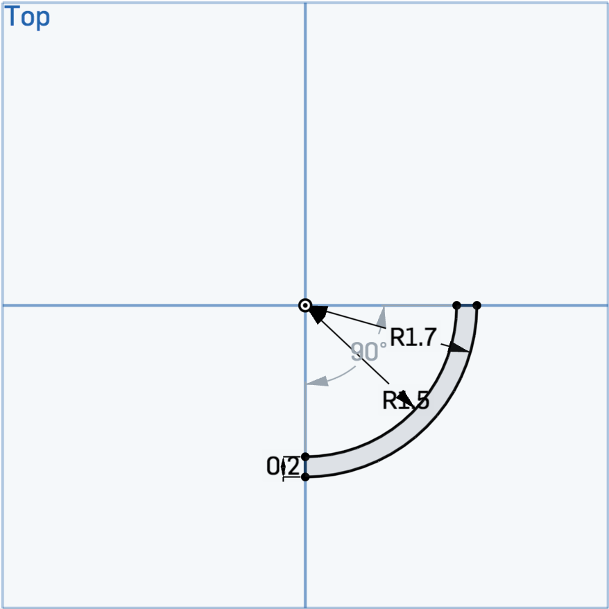
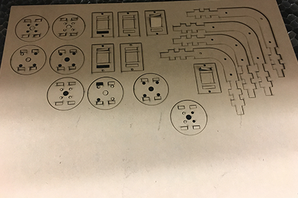
These are the design for the arm. The 2D feature of the design makes it suitable for laser cutting. One copy of the upper drawing, and two copies of the lower drawings will be used to assemble one arm.
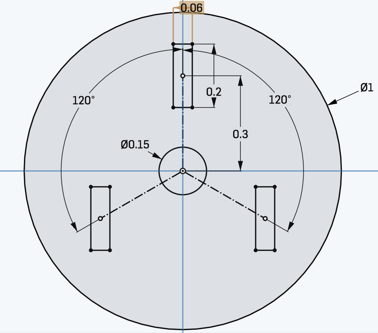
This is the cenrtal ring for fixing the arms. The hole in the center can be used for placing wires. Three copies of such ting will be used in a single arm.
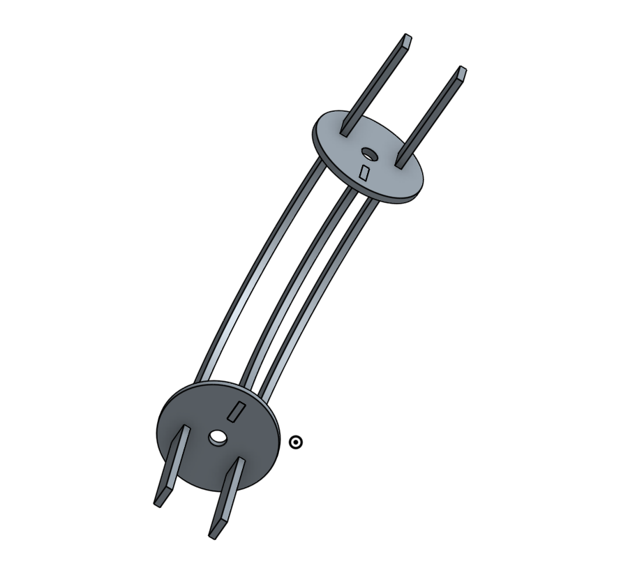
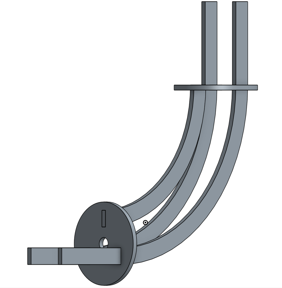
This is the 3D view of assembled arm. There will be one more ring in between the two rings, however, I'm still learning how to add that ring in the assembly in OnShape.
Second CAD Design of the Gimbal
(From now on, I will only show the assembled figure of the design, until I have finalized the design.)
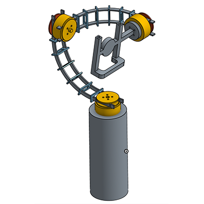
This is the overview of the 2nd design. In this version, I have changed the 3 supporting sheets in the arm to 2 parallel sheets. By doing this, the material needed for the arm will be much reduced, as well as the total volume.
Another big change I have made in this design is the phone holder. The phone holder will be ideally 3D printed and mounted directly to the last stage of the motor.
However, I realized that the semi-cicrle design for the arm was a bad idea, because:
- the shape of arm will make it occupy too much unnecessary space.
- more severely, since the 1st arm will be too far away from the phone holder, the 2nd motor can block the camera of my phone.
Therefore, I have no choice but to change my design again.
Third CAD Design of the Gimbal
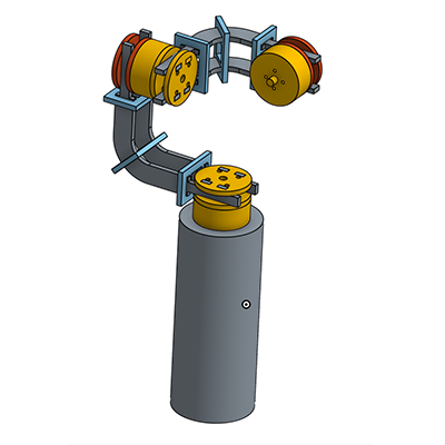
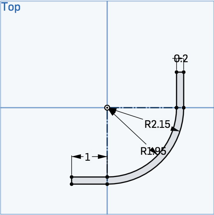
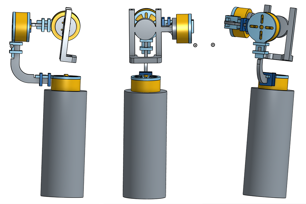
As shown in the picture, I have changed the shape of arm to two straight parts perpendicular to each other, with a small-radius curve connected together. Using this design, the two problems in the 2nd design can be perfectly solved.
Another point to notice is all the details I have added in this design. The screw holes and motor holders are designed with correct size that will fit with the motor I have chosen. The motor holders are designed such that they can fit with arm in a press-fit level, i.e., screws are only needed to fix motors onto motor holders.
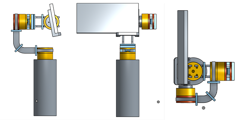
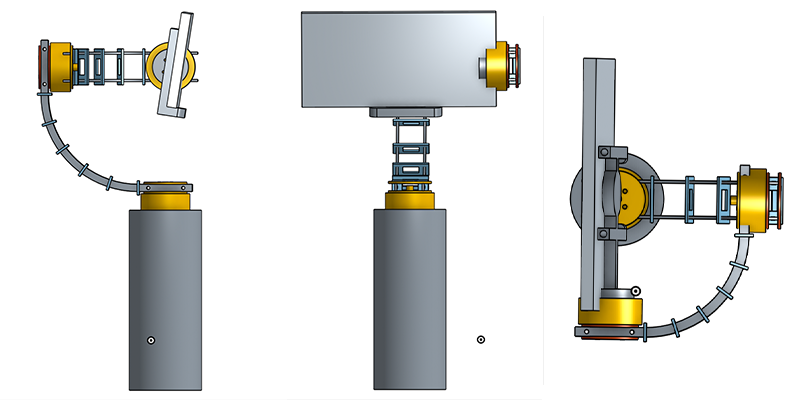
Three views of the third design.
Note that the distance from phone holder to the 2nd motos is much reduced compared to 2nd design, which can leave the camera unblocked. Besides, this change can also make the whole gimbal smaller.
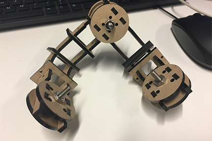
This is the photo of this design fabricated by laser cutting of 3mm acrylic plate. Actually, this design proves to be very robust. The problem with it is that it's too ugly and bulky.
Since I have already decided to use very strong materials like titanium and S.S. 304, I will reduce the size of the design.
Final design for the gimbal.
Here is the frame cut out of acrylic:
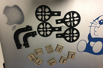
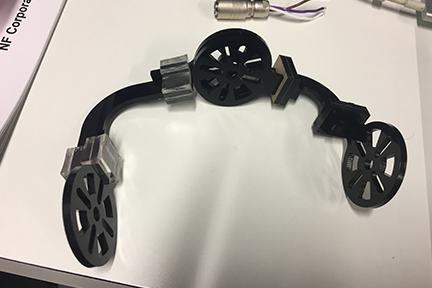
The final version of the gimbal looks much better and occupies much less space.
This is the frame made out of 3.5 mm titanium (Ta15):
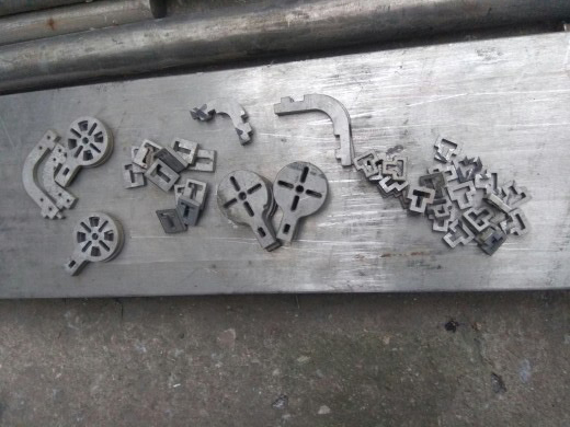
It looks even better than the design assembly picture!
Choices of Materials
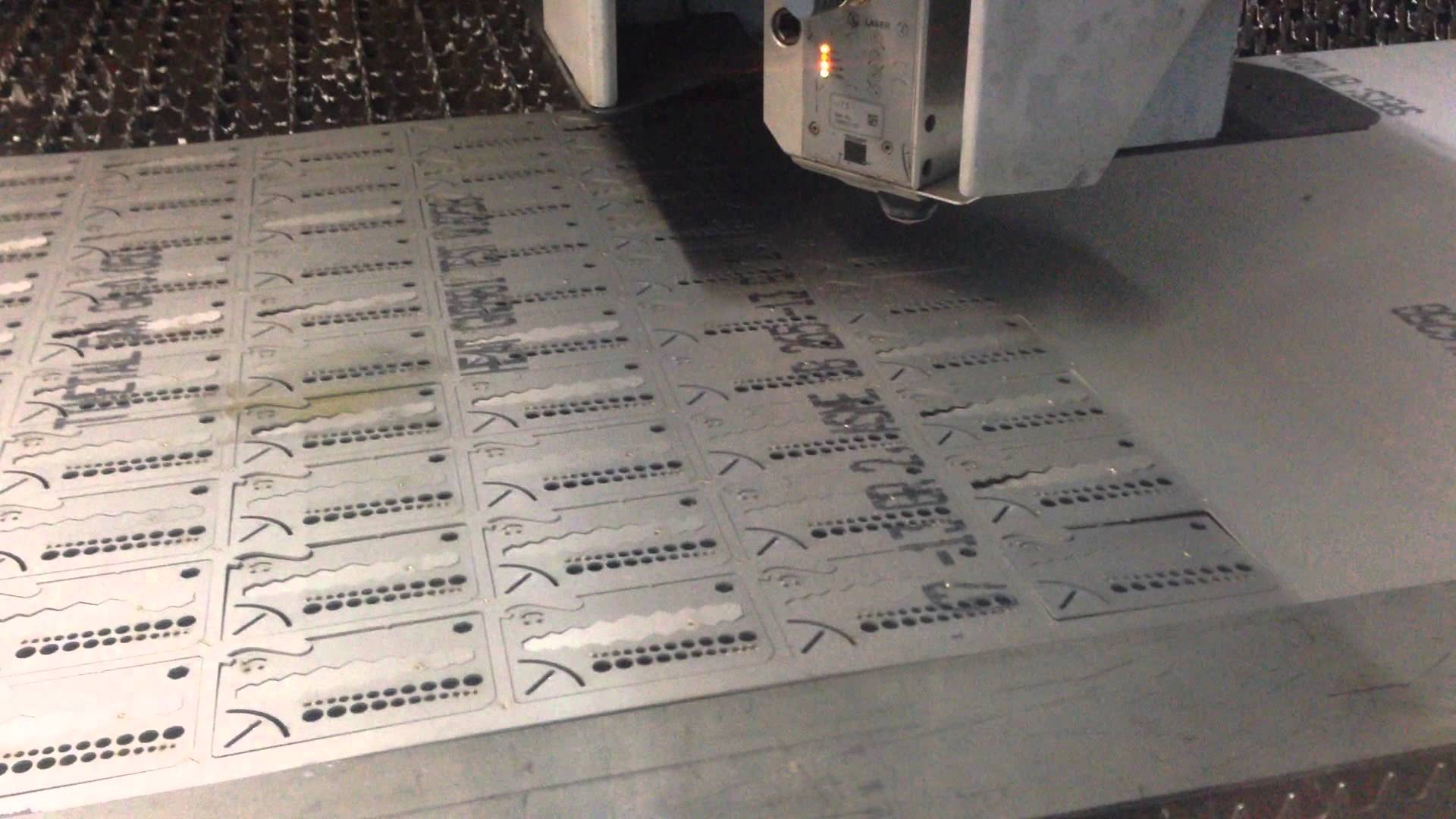
Since my design is particularly suitable for laser-cutting, I will make decisions between different sheet materials.
Before we start, we need to make sure we know what factors to consider when we're making decisions on materials:
- Cost: low cost will be great.
- Strength: should be as strong as possible (within my budget)
- Availability: it should be delivered well before December (or at least before the open house for my presentation).
- Other properties: should be suitable for laser cutting.
After I spend some time searching online, I have found following materials might be suitable in my final project.
Acrylic Sheet
This material is commonly used in laser-cutting. It's cheap, and can be found in almost all websites. However, because of its low robustness, I will only use acrylic for protocal fabrication.
On McMaster Carr's website, a "Scratch-Resistant Acrylic" with 12" x 12" x 1/8" will cost $6.74, and can be delivered within three days.
Carbon Fiber
Carbon fibers are lightweight and strong, which makes them very popular in drone and bike fabrication. However, they are usually very expensive.
On McMaster Carr's website, the 12" x 12" x 1/8" carbon sheets will cost $100 and can be delivered in 3 days. However, this is way too expensive for my project. Therefore, I turn to another website, and find there are a lot of good deals on carbon fiber sheets.
On Aliexpress's website, the 300 mm x 200 mm x 3 mm (roughly 12" x 8" x 1/8") will cost about $24, and it takes 12-30 days to deliver. This really sounds a great deal.
Density: 1.6 g/cm3
Aluminum Sheet
Aluminum sheets and brass sheets are common materials in any machine shop.
On McMaster Carr, the 12" x 12" x 1/8" aluminum sheets can be purchased at $40 each, and delivered within three days.
On Aliexpress, aluminum sheets with similar dimensions will be $12, and can be delivered in 12-20 days, which is reasonable for me.
Density: 2.7 g/cm3
Titanium Sheet
Titanium alloy can be extremely robust, and lightweight at the same time. Actually, titanium should be more favorable in water-jet cutting, instead of laser cutting.
On McMaster, the High-Strength Grade 5 Titanium Sheets with dimension of 12" x 12" x 1/8" can be $300-$400 each, which is far far beyond my budget for the final project.
On Aliexpress, the grade 5 titanium sheet is $16 each with dimension of 150 mm x 150 mm x 3 mm, and can be delivered within 12-20 days.
Density: 4.51 g/cm3
Summary
Here is a detailed comparison for materials:
| Materials | Tensile Strength (MPa) | Density (g/cm3) | Price ($) |
|---|---|---|---|
| Aluminum 6061 | 270 | 2.7 | 8 |
| Carbon fiber | 200 | 1.6 | 20 |
| Titanium Gr.5 | 950 | 4.5 | 16 |
| S.S. 304 | 500 | 8 | 16 |
After spending a lot of time searching online and chatting with salses persons from online stores, and based on the fact that laser cutter in the physics machine shop can only cut S.S. up to 2 mm, I decided to make my gimbal out of titanium and S.S. 304.
Since I cannot cut titanium sheet here, I have ordered three sets of gimbal frames made out of 3.5 mm titanium alloy, and asked the salse person to cut the titanium using their laser cutter, with drawings provided by me. Each set of titanium parts plus machining will cost 12$, and will take three weeks to be delivered.
At the same time, I will order one 12"x12"x.065" S.S 304 sheet from McMaster, and then I can tes the electronic designing by the S.S. frame.