Final Project: CORE XY Plotting Machine
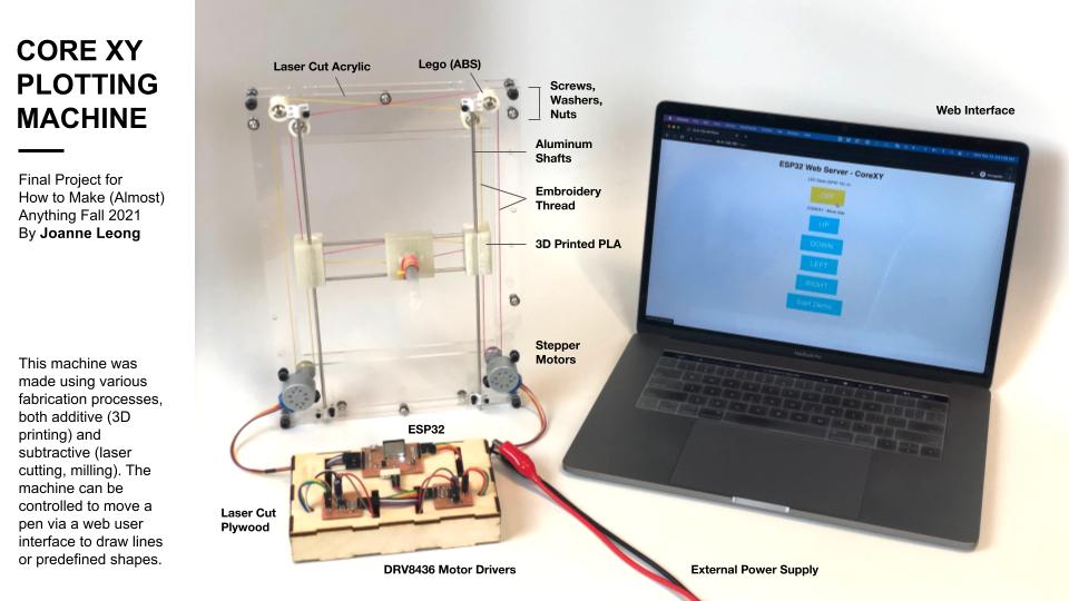
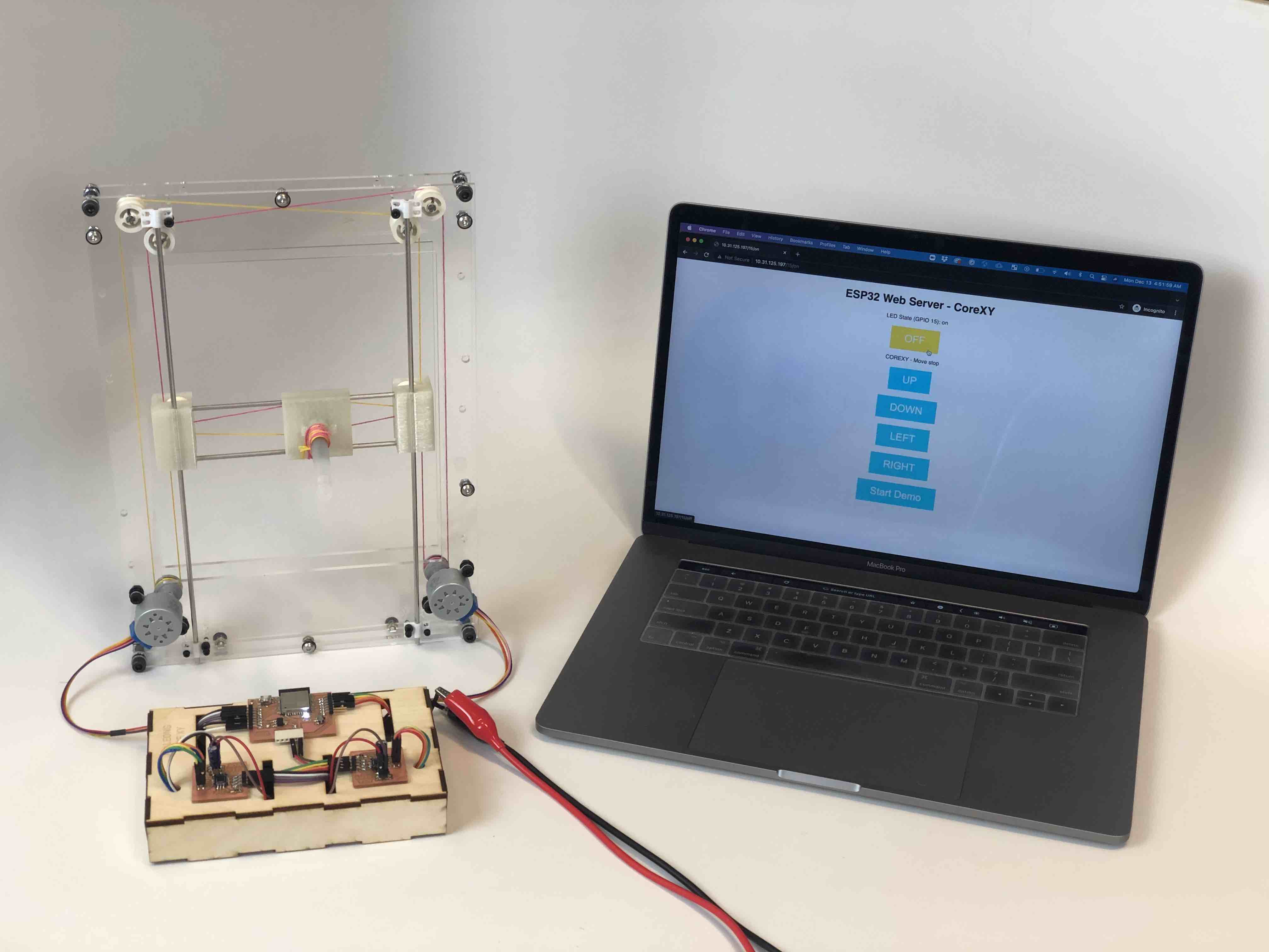
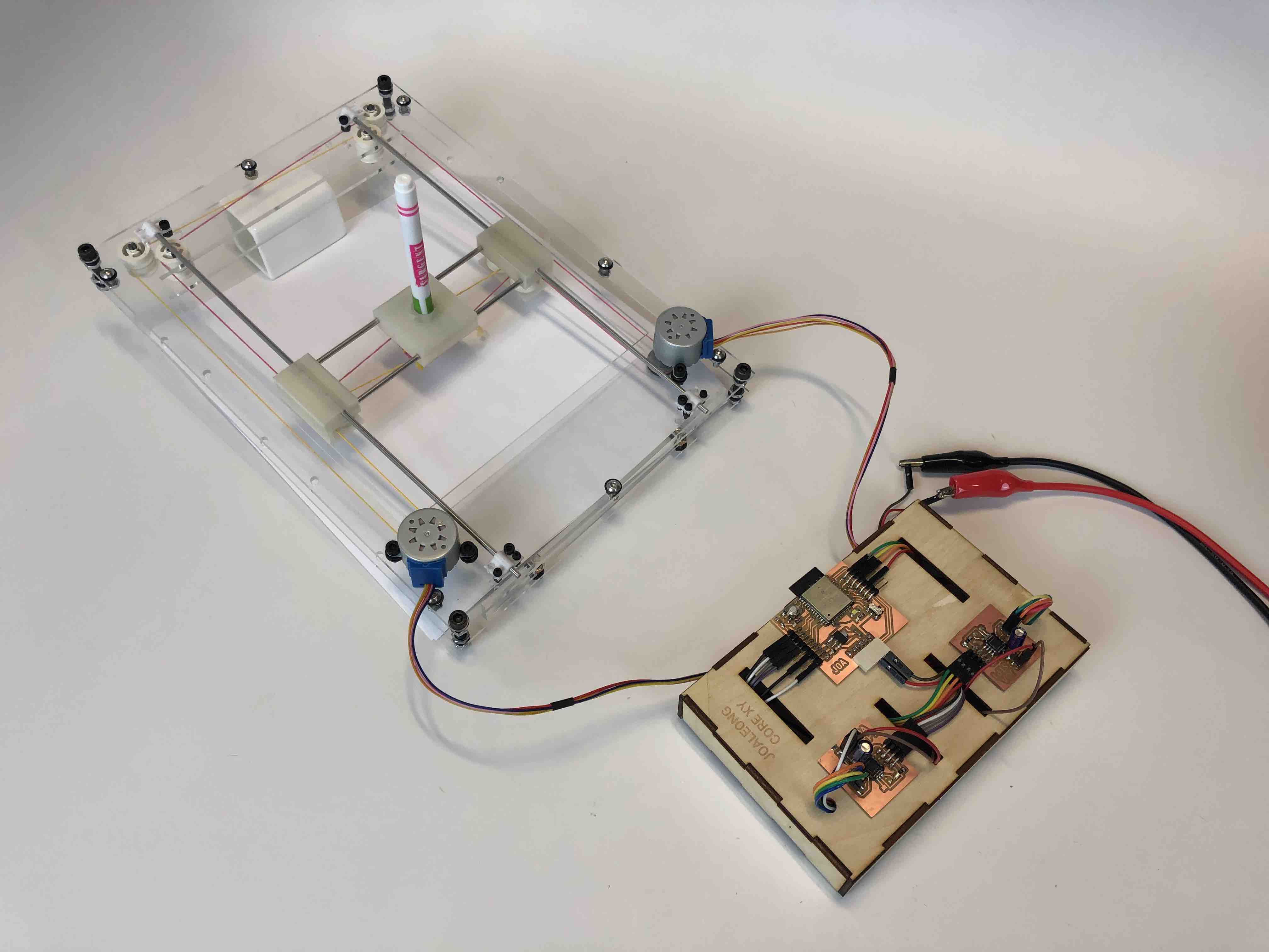
For my final project, I made a CORE XY plotting machine! There were so many things I had to learn in the process of finishing this design “spiral”. Here I cover my process, what I learned, and the result of this journey. If you want to know more, continue reading the documentation below!
What does it do?
It’s essentially a plotting machine made from the CoreXY system. This is a particular design for a motion system that relies on two motors and a belt system to move a head in two directions.
Who’s done what before hand?
I mostly referenced the CORE (X,Y) website to understand this mechanism and how it operates.
Other sources of inspiration for my design include on body interfaces and machines such as:
A week before this final project was due, CBA held a “Mechanical Machine Design” week. Quentin and Rob made a larger scale Core XY machine. I talked to them for some ideas as well.
Materials & Cost Estimation
Many of the materials I used in my final design were things I received courtesy of the lab. The only things I purchased that was incorporated in the final design were the aluminum shafts. I include a link to a possible provider and a unit cost (USD) per order. Approx. total cost is 71.25 USD.
| Material | Qty | Link to a Provider | Cost | Approx Unit Cost |
|---|---|---|---|---|
| 3 mm acrylic | 24”x24” | MakerStock | 24.95 | 25 |
| Screws and Washers (M3,M4,M5) | 14 pieces | Amazon | 23.99 | 2 |
| Embroidery thread | 2 skeins | Amazon | 13.49 | 0.25 |
| PLA plastic for 3D printing | A few grams… | Amazon | 24.99 | 5 |
| 3mm diameter aluminum shafts, 30cm | 3 shafts | Amazon | 8.89 | 4.50 |
| 3mm plywood | 1 sheet | Amazon | 18 | 6 |
| 2 Stepper Motors - 28BYJ-48 5V Stepper Motor | 2 motors | Amazon | 6.99 | 7 |
| Copper Plated Circuit Boards | 1 sheet | Digi-Key | 15.86 | 12 |
| Electronic components | 20 ~ | Digi-Key | 10 | 3 |
| ESP32D Wifi & Bluetooth MCU | 1 MCU | Amazon | 21.99 | 4.5 |
| DRV8436 Motor Driver Breakout Boards | 2 breakouts | CBA - Z. Fredin | N/A | n/a |
| Jumper wires | 20~ | Amazon | 5.99 | 1 |
| Lego Parts - pulleys and 1mm axles | 8 | Brick Owl | 0.01 | 1 |
Process
The process certainly wasn’t linear so instead of a numbered list, let’s go with nuggets! There were basically 3 main categories of things I had to tackle:
- Mechanical Design
- Electronics
- Software
In this section I will address:
- What parts and systems were made?
- What processes were used?
- What questions were answered?
- What worked? What didn’t?
- How was it evaluated?
- What are the implications?
Mechanical Design
This was possibly the hardest portion of this project for me, and arguably the most critical to have a machine in the end. I felt like while I knew where I was going on a high level, I didn’t know the ABC’s of Mechanical engineering to have things actually materialize. Some questions I had were:
- I have motors, but how do I actually attach things to it so that I can make them move things?
- I know I need things to slide around, how do I make rails that work smoothly?
- How do I cut an aluminum shaft in half?
- How do I actually design all the components to fit together?
- 3D prints and Laser Cutting - how to handle clearances?
- 3D prints - how to ensure structural integrity?
- How to make a nice box to house the electronics?
- Tensions versus Belts - How do you get good tension and grip?
The processes I used included:
- CADing
- Laser Cutting
- Drill Press
- Circular Saw and Sander
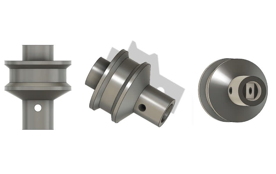
Motor Couplers - How do you actually attach things to motor shafts?
For the motors and how to attach something to it, I learned of things such as “couplers” so you can attach shafts to them. In my case though, I wanted to keep my machine to a slim profile, and after discussing this problem with Rob and Cathy, I learned that 3D printing could be the way to go. So I started off designing a kind of cap to sit on the motor hub, which was a challenging first exercise. I began by measuring the dimensions of the motors I have, and realized that they’re also posted online. I then modelled the shaft of the motors and subtracted this from the shape that I wanted to essentially mount to it (a shaft of the right length, and a pulley on it that would move the strings). The next question I had was about fit - how do I make sure that what I print actually fits snugly to the motor shaft? I was told that it was a matter of “clearance” and that a bit of experimentation with printing would be needed to get a good fit. Cathy also mentioned to me that I should design small holes on the sides of the print so I could insert a set screw to help keep the print tightened the shaft (which conveniently had a D profile, as in a flat face cut into it, instead of round shaft profile). The first print I tried was loose - I offset the walls by 0.4mm thickness- and then I printed it tighter. Next I tried a different clearance and found that offsetting the walls of the cylindrical hollow out by 0.2mm on each side (0.4 mm difference in diameter) given the lab’s Prusa 3D printers got a satisfying fit. When I pushed the part onto the motor, it fit quite snugly when I twisted it, and when I pulled it off, it made a very satisfying popping sound.
Rails - Textbook Standard Mechanical Parts and How to Ignore Them
I originally was thinking that I could possibly 3d print something, but I didn’t like the concept of plastic rubbing against plastic. I imagined that it would want to get stuck or wear down. Therefore I looked at the examples on the CORE XY website and also had discussions with Cathy, Zach and Dave about this topic. It seemed like standard way would be to buy metal shafts and linear bushings or bearings to get something to glide over them smoothly. However, I was inspired by the fabric version of the CORE XY that didn’t use rails at all. I think it works because they have a fabric base which essentially offers the structural support.
As I wanted to have a very light-weight construction, I opted to buy 3mm instead of 5mm shafts, and chose aluminum instead of steel shafts. Later, I learned from Zach that Steel would have been the choice he’d suggest since they are much stronger (would be less likely to bend, which is important in a machine like mine that spans them for some distance) and are typically made with a smoother finish, and are often designed to have maching bushings or bearings that can glide on them. Unfortunately for me, I didn’t have that knowledge - but fortunately for me the aluminum shafts I did get turned out to be good enough quality that the plastic didn’t stick to them and actually glided really smoothly over them! I also had decided to buy linear bearings, but when I tested them with the aluminum shafts, they tended to grind and get caught on it instead of slide over the shaft smoothly. Therefore, I opted to not use them in my design and tried to 3d print a part to move over them directly. It turns out that this was actually way smoother, so I went with that!
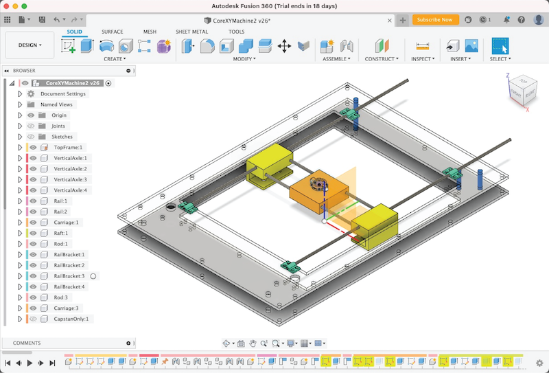
Determining Overall Dimensions - Learning to Model an Assembly
This was actually one of the biggest challenges I faced. While we had started learn about some CADing in the earlier weeks, this is the first time I realized I would need to model an assembly to make sure all the parts I designed were compatible with each other in dimension. Before this, I had never modelled something so complex. Rather, I had modelled individual standalone pieces which I could know the dimensions of before hand. In this case, the design of this machine had many variables, and it was too challenging to keep track of dimensions on some kind of spreadsheet. Therefore, I watched this really great tutorial on Youtube and did some serious work to learn how to design my own assembly in Fusion 360, where it would be possible to manage all these separate components.
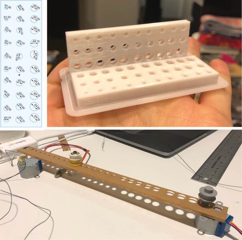
I also went ahead and tried to assemble this once using cardboard which taught me a little bit more about fit.
Clearances and Gauging Precise “Fit” of Parts
This was a recurring theme in my project. Again and again, I was wondering how do you get things to fit correctly? Some kinds of “fits” that I needed to achieve were:
- quite a tight fit, but loose enough that the printed part can glide smoothly over the rail / a part can spin quite freely but is still constrained
- a press-fit, where I can make things fit snugly without needing glue
Meeting this challenge required two bits of wisdom:
- When modelling pieces, it’s typically better to model them precisely. Then you can offset faces in Fusion 360 as the last step and play around with the clearance.
- You actually need to make several prints / laser cuts to test what is working in the real world. (this is a painful reality, especially when printing takes time!)
I ended up designing special test prints and laser cut designs to test different sizes. As I bought a 3mm aluminum rail and needed to see what size to make holes for both kinds of fits. I also learned that the orientation in which you print a hole can change its shape and affect the fit. Therefore I made this cool test piece and printed it both horizontally and vertically. This was to test the fits given that some of my pieces had holes in it that inevitably needed to be printed such that it was unavoidable that some holes would be printed in one orientation than another.
Another thing I learned is the idea of “chasing the hole with a drill press.” This was miraculous bit of skill I learned from Zach which was very helpful! He taught me that to achieve a press-fit, it’s better to print the hole too small and chase it with a drill press. He taught me how to select a drill bit, install it, and secure my plastic 3d printed pieces on the drill bed for safe operation. As usual, proper safety practices to use this include: wearing glasses, tying one’s hair back, ensuring any dangling bits of clothing are secured out of the way, and having someone else in the lab with you, at least within shouting distance to make sure you can get help if needed.
Likewise, for laser cutting a I made a test pieces with many different sized holes in it. This was originally when I realized that Illustrator 2021 has an issue with accepting .DXF files, and that I needed to export it to Illustrator 2020 if I wanted to upload a PDF to Corel Draw on the lab’s laser cutting desktop machine.
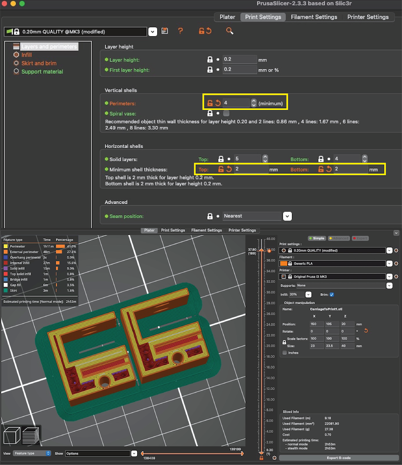
3D Printing Parameters to Maximize Structural Integrity
One part of my design was particularly suspicious looking. As Dave pointed out, the C-shaped rail brackets that I designed look fragile. The C shape created a kind of cantilever, where pressure at the end of the cantilever could encourage it to snap off. I was encouraged to make this part thicker to reduce the chance for breakage. I upped the thickness of the walls from 2 mm to 4mm thick.
Zach also suggested something cool - going into the Slicer and changing the wall-thickness parameters. We also talked about print orientations for parts. Essentially, I had to consider the kind of “grain” that the piece would have. If the grain ran perpendicular to the cantilever, it would be particularly fragile. However, what we realized is if I orient the print that the bracket is on it’s side, the printer would print an outline around that section which would help it be strong. Also, with the thicker wall thickness, it could ensure that this thin part would be printed at 100% density in comparison to the larger part of the print. This would also help it stay strong.
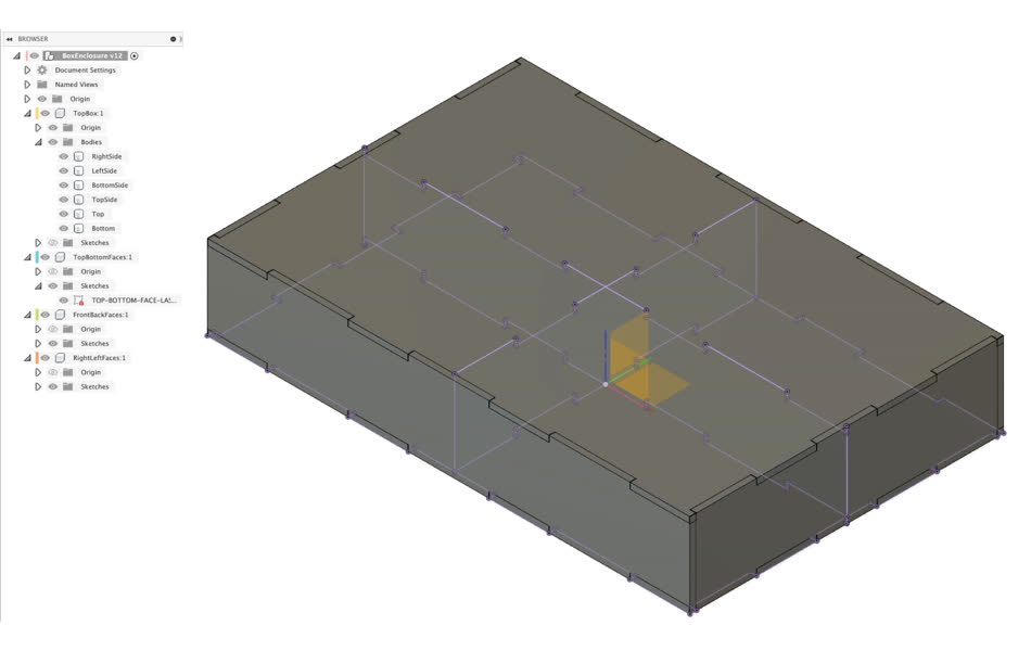
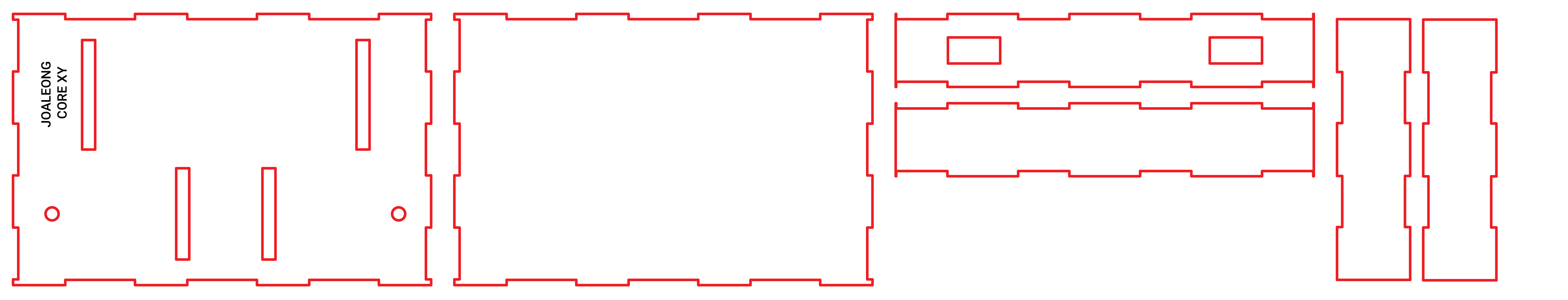
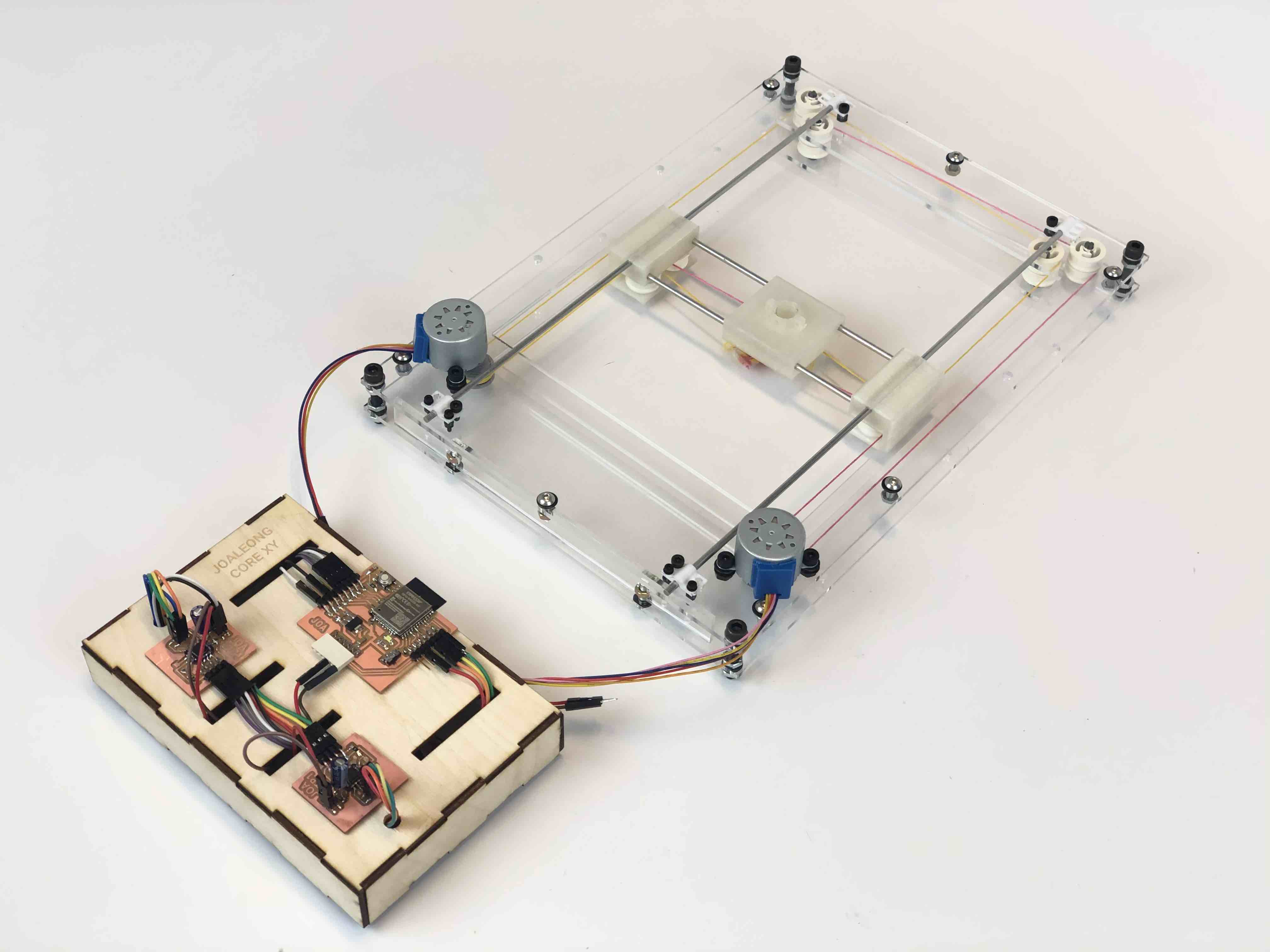
Electronics Housing - Laser Cutting a Box with Finger Joints
For the electronics, I wanted to package it nicely. I found a nice piece of scrap plywood courtesy of other students and decided to laser cut a box with finger joints. While I had somewhat gone through this exercise using FreeCAD, I found myself frustrated with the experience and decided to tackle things in Fusion 360. To do this, I first measured my boards to determine the necessary overall size. I then designed a box in Fusion 360, and used the finger joints plugin to add this detail. This required some trial and error. I initially didn’t realize how it worked and modelled the sides of the box as separate bodies that had faces touching but did not intersect. It turns out though that it is critical that there is a portion of these faces that do intersect with each other in space to add these finger joints. Once I had that a-ha moment, everything worked. After applying the finger joints, I projected each face of the box and exported each as a .DXF file. I noticed that exporting DXF files into Illustrator 2021 is buggy! For some reason, this version of Illustrator has a bug which means that the dimensions will not come out correctly. In Illustrator 2020 this is not a problem. In illustrator, I added some of the detailing I was looking for, including slots and holes for the jumper cables to be lead through, and also the text detailing on the top face. I then used the GCC laser cutter. I did some test cuts to find good dimensions I determined the following:
Getting Tied Up With Strings
I imagined that the strings would be difficult to tension, and I didn’t really have a sophisticated plan for making sure that they would be held with enough tension. I hoped that tying it would be enough, and that a simple hole on the gantry would be enough to secure the strings to (although I had imagined a future sprial could include a kind of rachet mechanism). This was mostly a trial and error process, coupled with lots of hoping. This is also not a fun process when you’re under stress and trying to deal with tying tiny knots precisely. I managed to tie it well enough that it would move, but saw in it’s initial baby-steps that it tended to drift one side when it should only move up and down. By this I learned that the strings are ideally equally tensioned. Fortunately Zach was very dexterous and was able to help me achieve better and more equal tension across the strings. He also taught me some helpful knots to tie - essentially a double knot but instead of having the string ends go through the same hole, you tie one knot adjacent to the o ther.
Electronics
Fortunately, what I learned and tried in earlier weeks during the semester paid off. In Networking week, I was able to re-use my ESP32 board which I designed, fabricated and coded to act as a server which a computer could access! As part of catching up for outputs week, I also designed fabricate the board I designed for Zach’s motor driver DRV8436 breakout board. The final project integrated these pieces to be used for the controls.
The process for making these were:
- Designing the schematics in KiCad
- Designing the PCB layouts in KiCad
- Exporting the PCB layouts as PNGs
- Using Mods and the Roland Milling Machine to Mill the layouts
- Stuffing the Boards with the Electronics
To learn more about the ESP32 board, look here. To learn more about the motor driver breakout boards, look here.
In integrating these, the challenge I ran into boiled down to the power supply, which Anthony helped me to debug. Once we were sure that the boards were okay and it wasn’t the size of the capacitors, we tried different power sources. Initially I was trying to power my circuits via the USB of my laptop. This produced weird behavior, where it could successfully run one stepper motor, but not two at the same time. Even more strange was the fact that it would be somewhat random which motor would work, and which would not. We tried different permutations for connecting my motor driver boards to the steppers, but it we found that the motor driver boards did not consistently predict which stepper motor would fail to move. When we switched out my laptop for an external power source, both stepper motors ran consistently. We figured that the laptop, while it provided the correct voltage of 5V, could not produce enough current to support the circuit. Therefore in my final design I ran the machine with the external power source, and everything worked fine from there.
Software
For the software piece, I expanded upon the code I had worked on during Networking week. I coded everything within the Arduino IDE, in a single .ino file. Essentially, the ESP32 can act as web server, which is really neat! I updated my code to have more buttons that when clicked trigger the motors to move in a coordinated fashion. In the end, I had the functionality to move the gantry up, down, left and right. I also coded a function for the machine to plot a predefined shape.
Code - Core XY Controller (.ino)
More Photos and Videos
Demo
Process
Big Thanks
Many thanks to all the people who shared their wisdom with me along the way, especially the TAs Zach, Anthony and Dave, and Cathy for her MechE knowledge!