Individual Assignment
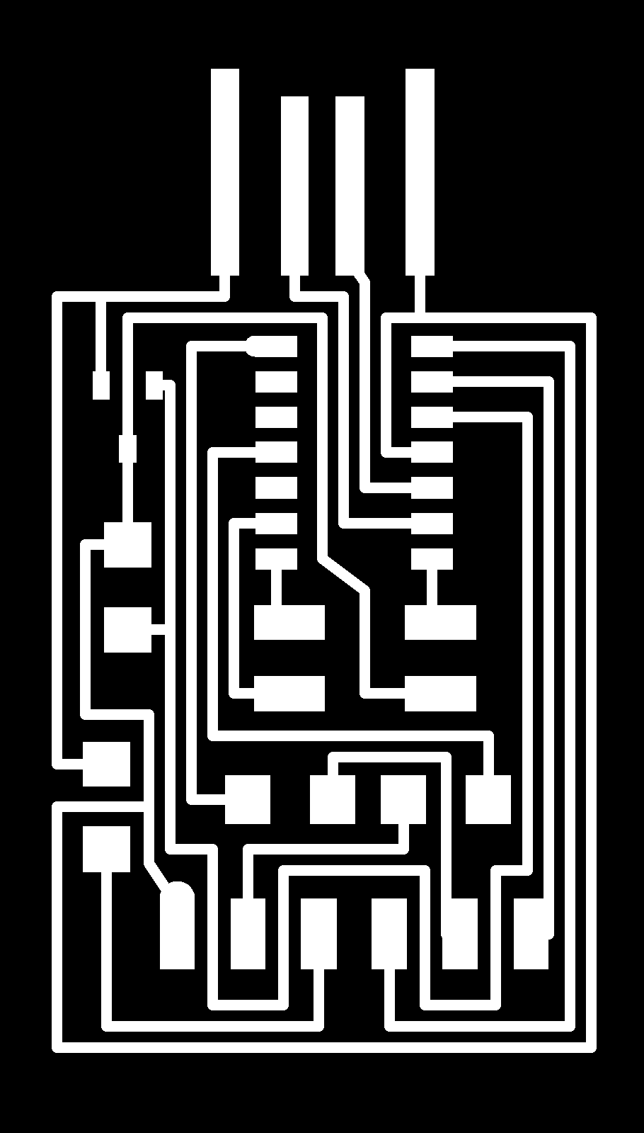
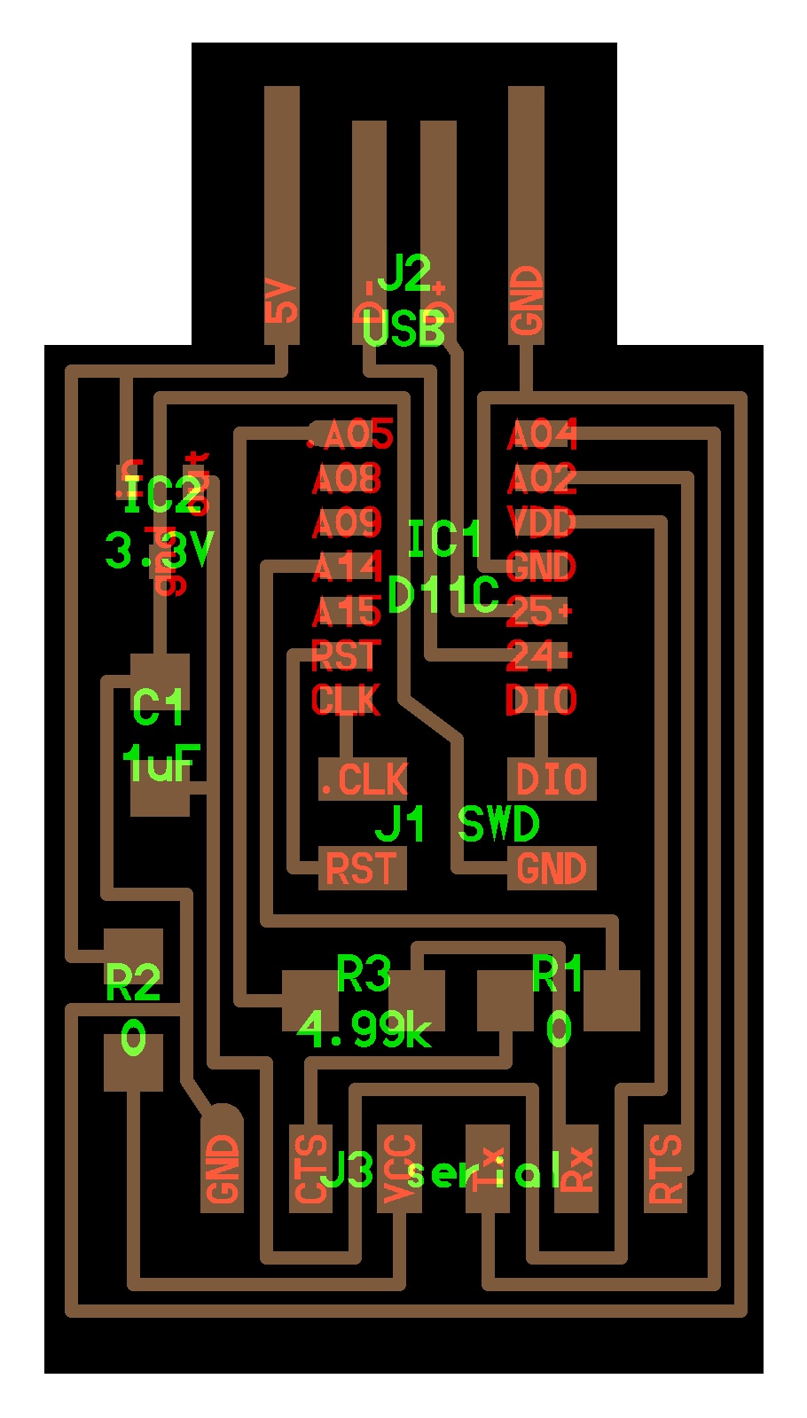
I’m using the provided class-provided PNG files for: “hello.D11C.serial.5V.1.1”
Materials List
These are all the things I’ll be using.
Equipment:
- A milling machine
- Mill bits. We’re using 1/64 and 1/32.
- Metal Scraper and Vacuum
- Fine Tweezers and Exacto Knife
Raw Materials:
- FR1 Copper Clad material (you can do single-sided the first time.)
- A not-good FR1 Copper Clad material (one you can damage)
- “Permanent” Double-Sided Sticky Tape
- Solder
- Flux
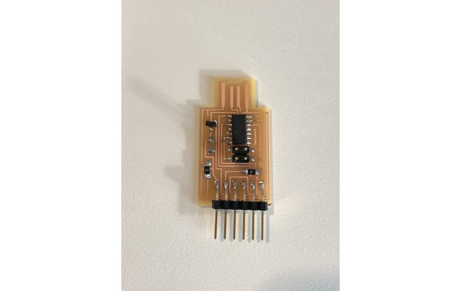
Electrical Components:
- 3.3V Regulator
- 1uF capacitor
- 0 ohm resistors (x2)
- ATSAMD11C4A
- 6 pin header (needed socket connectors, but we didn’t have!)
Set Up
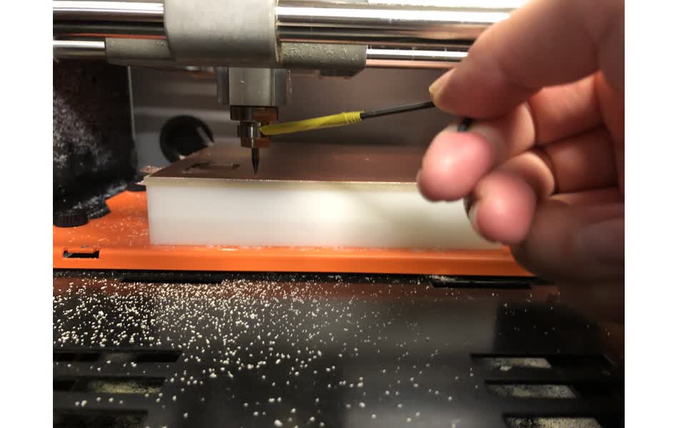
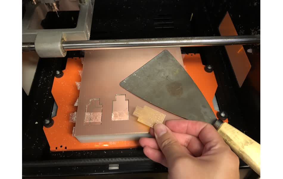
Using double sided “permanent” sticky tape, lay down a sacrificial board and then a board to cut from. In my case, these were already there and ready to go. Then, ensure that the correct mill end bit is there. To begin, I needed to use a 1/64 bit to mill the traces. Make sure it fits snugly by turning the screw. Make sure you change the “origin position” to point to where you want your piece to be milled. 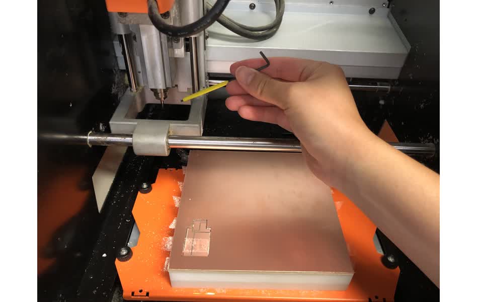
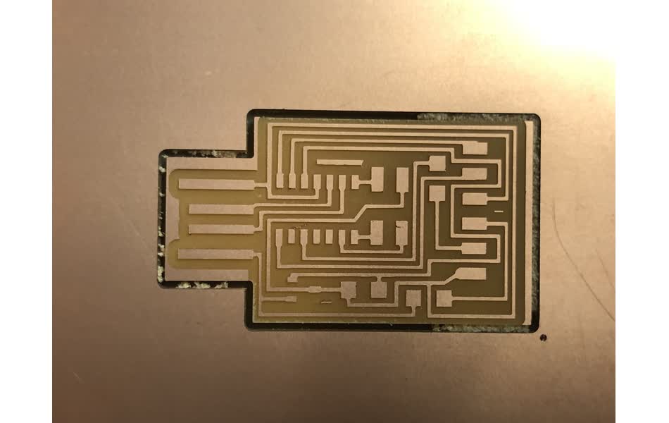
Mill Traces
Once the head is in the origin position, loosen the grub screw and let the mill end touch the board. Tighten the screw again. This zeros the head position on the z-axis. It’s good to have most of the drill bit being held by the collet. When completed, vacuum the dust. 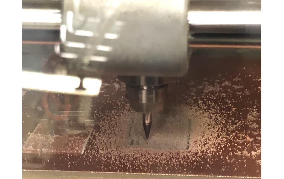
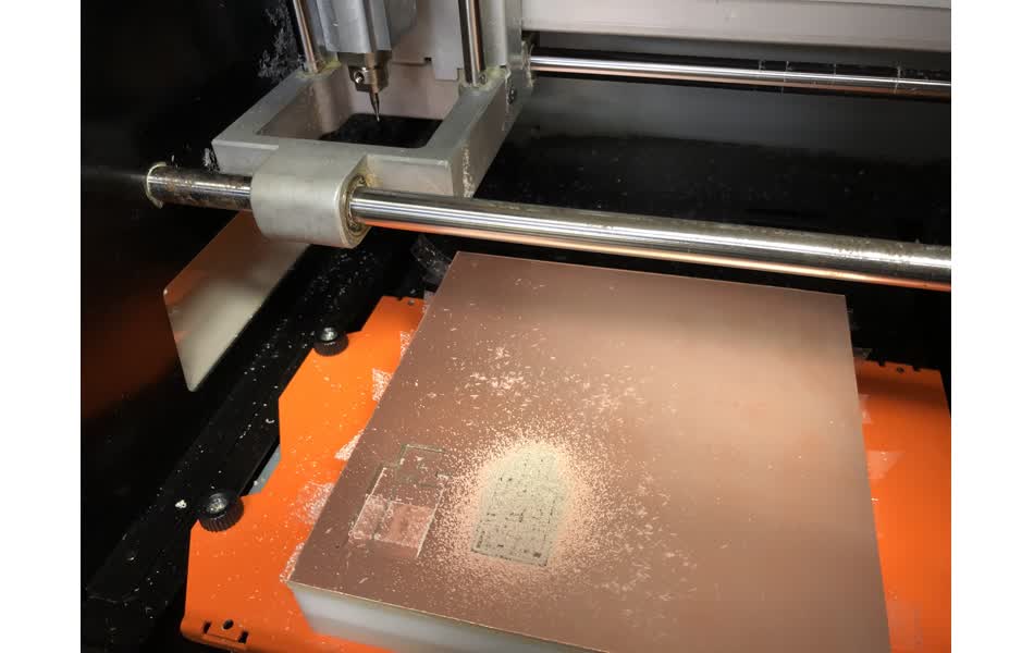
Mill Outline
Load the outline file. Follow a similar process to milling the traces, but replace the mill end bit to 1/32. 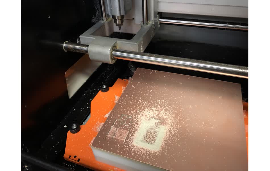
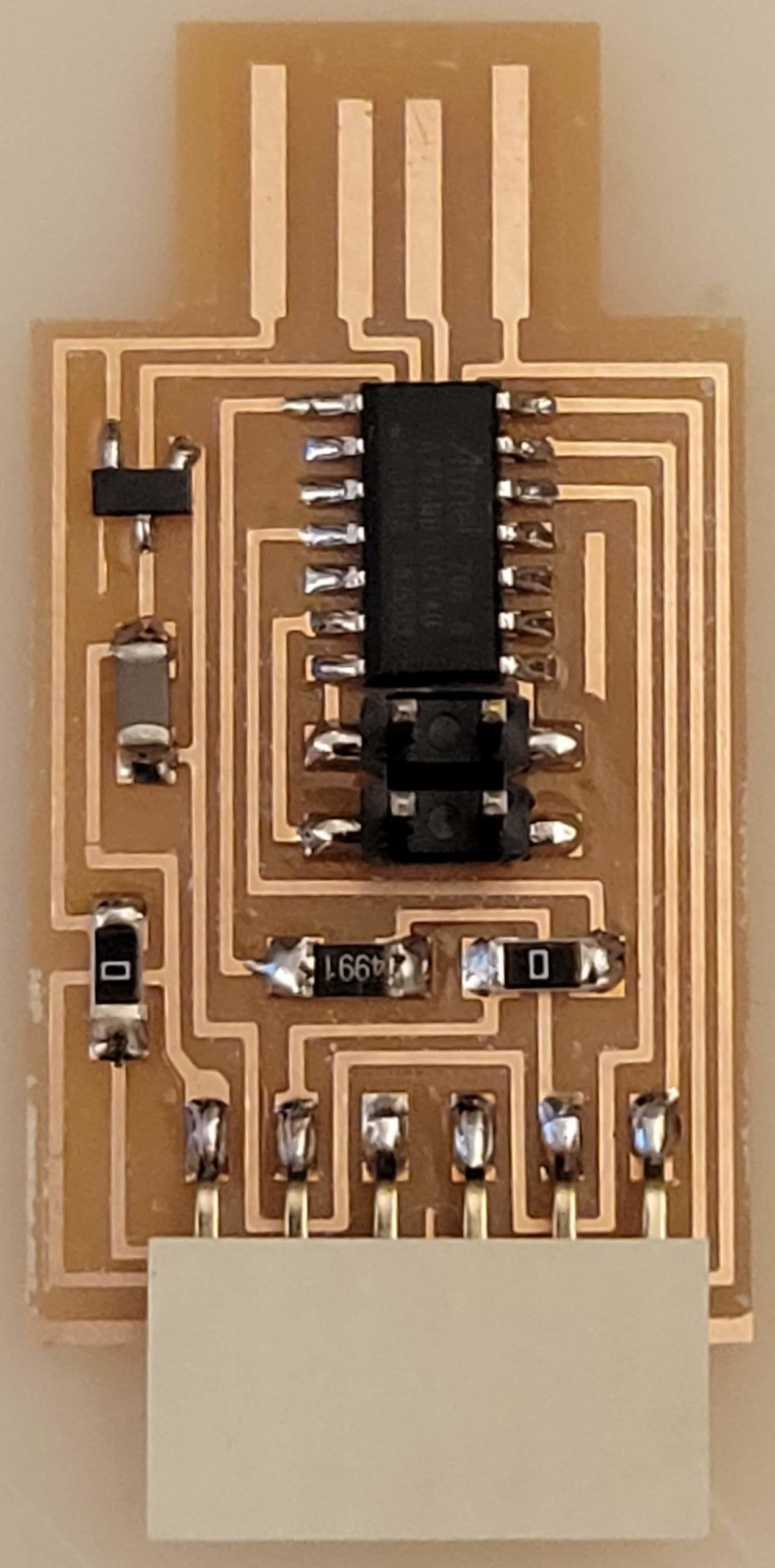
Stuff the Board
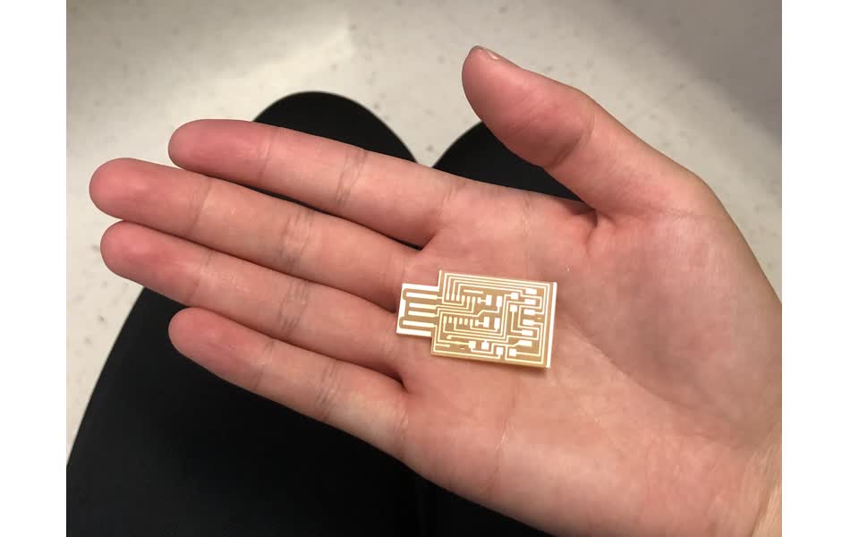
First, use an exacto knife to remove the conductive material that is not needed and wasn’t milled away. Then collect what components you need. Solder these pieces onto the board. Make sure you have an extraction fan for fumes. To position small components, first add flux to the pad and then add a bit of solder to it. After, with tweezers, hold your component in place and heat up the pre-applied solder. Press the component against the now softened solder with tweezers to put it in place.

I used leaded solder to do this. Because I was touching lead I didn’t want to to whip out my phone to take pictures. However, I was relieved to learn that the most important thing with working with leaded solder is not to eat any of it. So wash your hands well after touching the solder before you do something else like eating. And as my TA said, just do NOT use your board to stir your coffee ![]()
![]() .
.
I also learned that as you’re soldering, it is common to see fumes when the solder hits the iron. However, it is not the lead that is vaporizing. Infact, the solder has flux inside it to help it flow, and it is the flux that is vaporizing when it is heated up by the soldering iron. Therefore, you don’t have to be too scared of the fumes (it isn’t lead). It’s still good to not inhale such things though, so use some kind of extractor fan while you’re working to keep most of it out of your way.
Also, it could be handy to use solder without lead. However, I’ve been told by the TA that it’s typically harder to work with. It has a tendency to be “slushy” meaning that while you’re working with it, you need to be steady to not move the parts around while you’re waiting for the solder to cool and harden. It is a good idea to use this form of solder if you’re going to be passing such things to children. It is also a good idea to use this for the environment, since you’re not throwing lead out there when you recycle the piece.
Program the Board
Zach Fredin, our TA, helped us to program the AMD11C microcontroller for us. He used his own hardware to load the program. He also plugged our boards into his laptop USB port to power the chip while it is being programmed. I didn’t take a picture of this part of the process. However, it did load correctly without errors. ![]()
Structural Improvements
-
It’s recommended to plug your board into a USB extension cable instead of your computer! This is to make sure you don’t accidentally fry your USB port if your board has some flawed line that can short the pins of your port.
-
It is recommend to cut out a piece of card and stick it to the back of the pcb to make it thicker such that it can fit snugly into a USB port (i.e. “Shim” it). Most USB ports on machines are not designed to be load-bearing, so this will help to alleviate any pressure. (Or as mentioned, just use the USB extension cable.) Some others like to add solder to the connection pads to raise them up. However, this is NOT recommended because it’s hard to make this solder level.