Laser Cutting: Making a Construction Kit
Mission:
- design, lasercut, and document a parametric construction kit,
- accounting for the lasercutter kerf,
- which can be assembled in multiple ways,
- and for extra credit include elements that aren’t flat
My Process:
- Decide what I want to build: Organic shapes! How about a dragon?

- Sketch and Model
- Test Cuts
- Actual Cuts
- Assembly
How to Operate the Laser Cutter
- Load your file into Corel Draw. Set all the lines you want to cut to a
hairlinewidth stroke. - Check that the dimensions of your canvas match the bed. 960 mm * 610 mm.
- Turn on the machine. Focus the machine using the focusing tool (move the bed up and down until it just touches the tool).
- In printing preferences
- check “Extend” to make sure the whole canvas is used and aligned.
- Choose manual color specifications so you can set the specific settings for each color of line that exists.
- For standard materials, make sure that the air venting option is ON for each color.
- Put your material into the machine on the bed. If it’s cardboard, make sure to tape it down so it’s flat.
- “Print” aka cut your file. Select your file on the machine. Press Start. If you leave the lid open, you will see how the head will move but it will not cut.
- Lowering the lid and Pressing Start will actually start the cut.
- Watch that it doesn’t catch fire
 . If it starts a small fire, you can open the lid to make the laser stop shooting. If the fire is big, throw the fire blanket over it. Never stray far from the machine while cutting so you can catch any problems.
 - Once it has finished cutting, leave the lid down and let it continue to extract any fumes.
- Take it out and voilà!
| Settings | |||
|---|---|---|---|
| Operation | Speed | Power | DPI |
| Cutting | 2 to 2.5 | 100 | 200 |
Sketch and Model
I decided to use FreeCAD, after I saw the demo from Neil. Also, I liked that it:
- can be used for parametric design.
- is multi-platform tool (Windows, MacOS, Linux)
- is FREE to use.
Since I wanted to have quite a few degrees of freedom, I started with an octagon. This lets me have joins at 90 degrees and 45 degrees. My strategy was then to create rectangles that can be used to do cutouts. I had to reposition the rectangles and do line trimming and line deletions to get there. I also had to go into the panel to modify the constraints, and map them to the spreadsheet values. Make sure to actually flag cells in the spreadsheet with an alias, so you can reference them in your sketch. I also added fillets to every slot.
It was pretty cool, I needed to do some high school level trigonometry to create a formula to calculate the depth of each slot. SOHCAHTOA is forever etched into my memory. 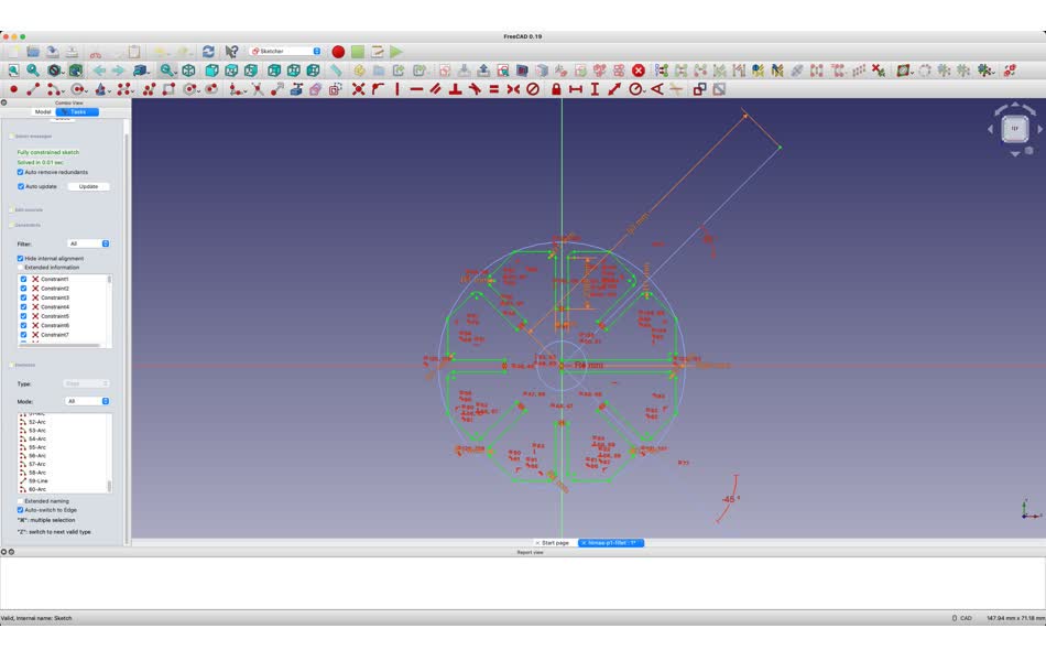
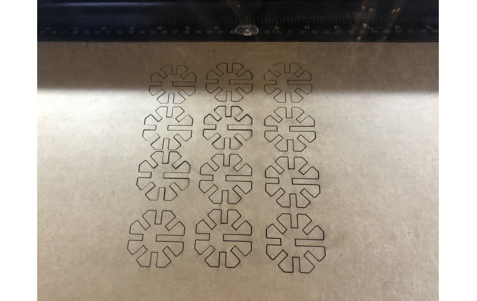
Test Cuts
I tested several different thicknesses for the slots. Although I measured 4.2mm with the calipers, I settled on a 4.15 mm thickness, which resulted in a snug fit. 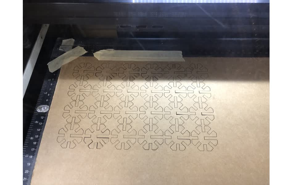
Actual Cuts
Once I decided on this thickness, I cut out 140 pieces from half of a single piece of cardboard! 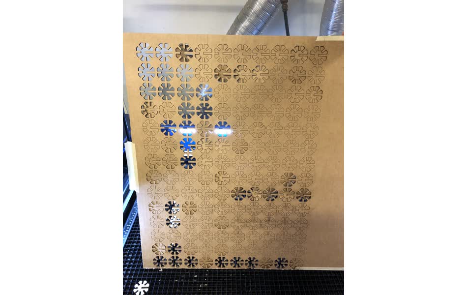
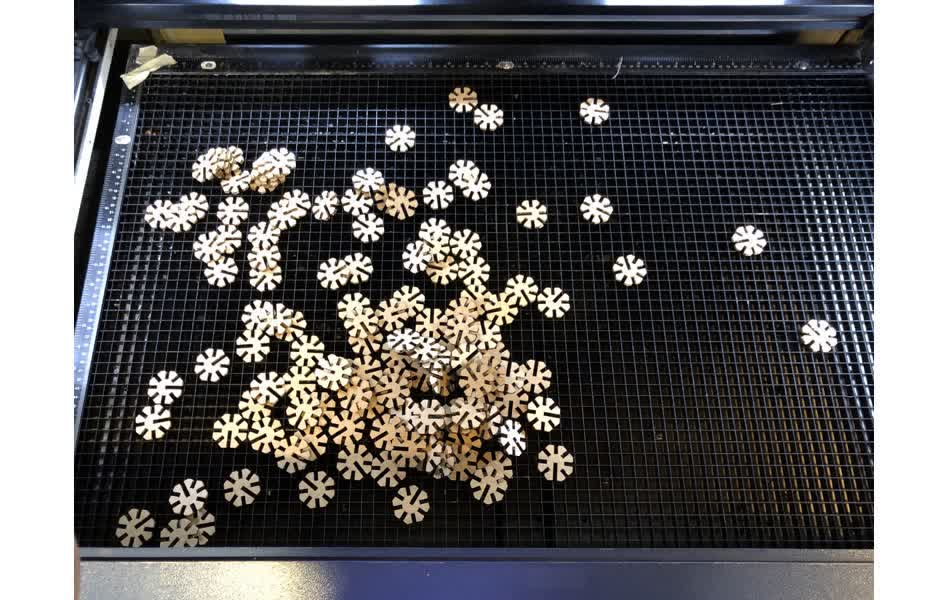
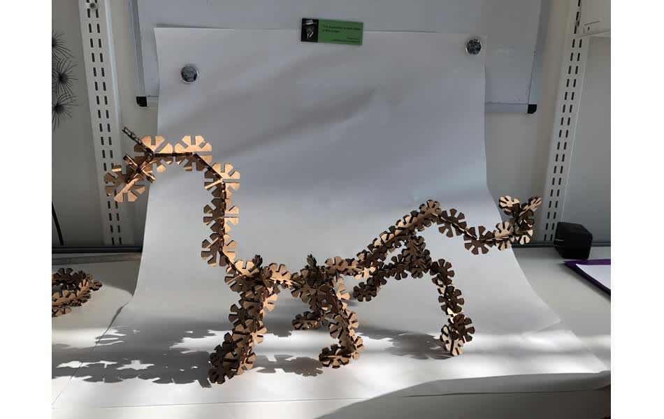
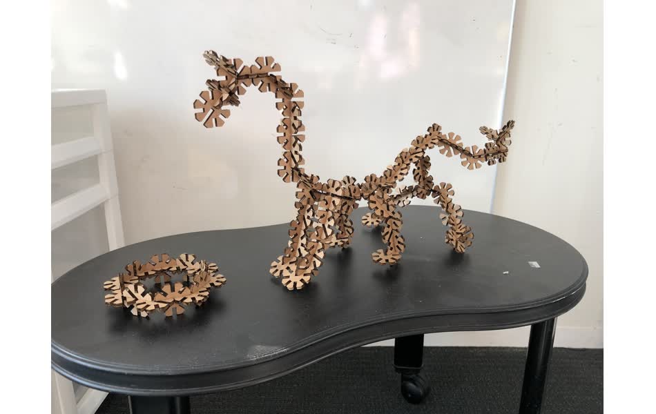
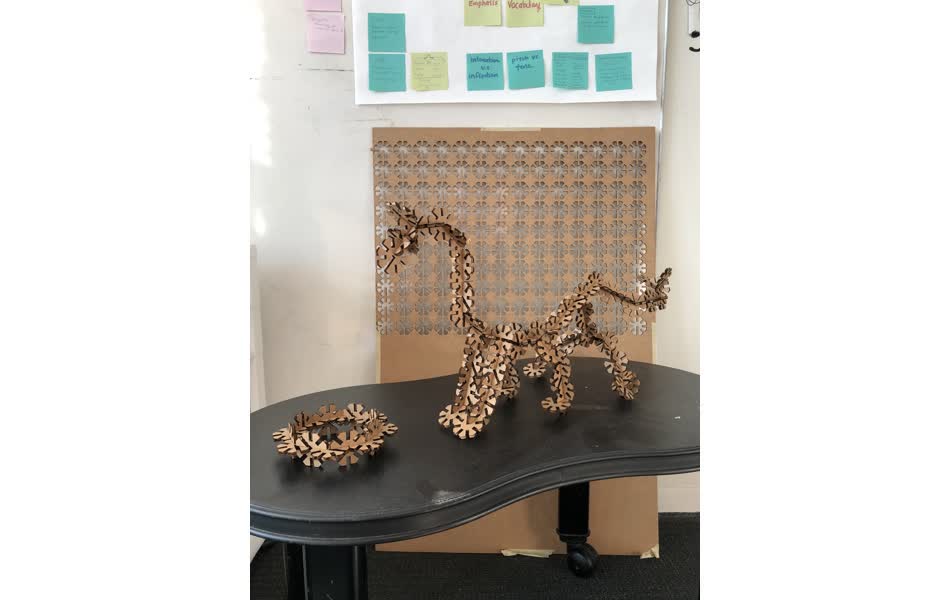
Assembly
It was very therapeutic to assemble structures with the pieces. Now the project is “How to Make Your Dragon” ![]()
![]()