Individual Assignment
Mission
Make (design+mill+assemble) something big (~meter-scale)
- extra credit: don’t use fasteners or glue
- extra credit: include curved surfaces
Process
- Skeching Ideas
- Modelling in FreeCad
- Computer-Controlled Machining
- Physical Assembly
- Enjoying the Final Product
Material and Tools
- 8 ft by 4ft OSB
- Software: FreeCad, Illustrator, VCarve
- Protective Glasses (don’t want shrapnel in your eyes)
- Ear Buds (want to avoid loud sounds)
- Hair tie (keep your long hair out of the way!)
- Shopbot CNC machine
- Vacuum (remove sawdust)
- Sander, Rasp
My Files
Back Panel (.FCStd) Side Panel (.FCStd) Plate (.FCStd) A2Plus Assembly (.FCStd) A2Plus Assembly Simple-Bodies (.FCStd) Final Design (.FCStd) Cut Paths (.ai) Cut Paths (.dxf)
Sketching Ideas
As a starting point for this project, I wanted to build something that I could actually make use of in my room. There were two things that woulld be practical for me - a standing desk, or a kind of shelf/shoe. ![]()
![]() Given what I learned about the material we were provided, OSB, I decided on building the shelf since the material could be rough but it would still be practical to use.
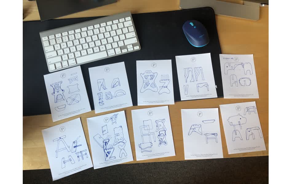
Given what I learned about the material we were provided, OSB, I decided on building the shelf since the material could be rough but it would still be practical to use. ![]() I started off by sketching some ideas for the structure. See some sketches here.
I started off by sketching some ideas for the structure. See some sketches here.
Modelling in FreeCad
I then decided to start modelling in FreeCad. In hindsight, I’m much more inclined to use Fusion 360 for future projects for reasons I’ll describe later. As I didn’t have much experience with modelling, I was pretty unsure what process I would need to follow. I went through multiple iterations of designs when thinking about the structural integrity of the design and also in trying to get the process correct.
I knew it would be helpful to make some sketches in the Sketcher workbench first, so that’s what I did. However, I wondered:
- How do I get an impression of the overall design in the software
- How do I make sure that the amount of material I proposed using would not exceed what I was provided.
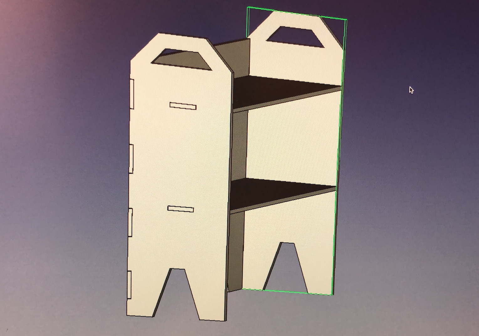
For the first item, I finally learned how to “assemble” designed pieces in FreeCad. I discovered that there are some plugins/custom workbenches that I could use, and opted for the A2Plus workbench. This lets one import different parts into an assembly based on some rules (e.g. make the face or edges coincident, parallel, etc.) I got more of an understanding how to create a new body or part for each piece of my desired structure, and save them as their own .FCSTd file. It was very satisfying when I had assembled a structure in FreeCad.
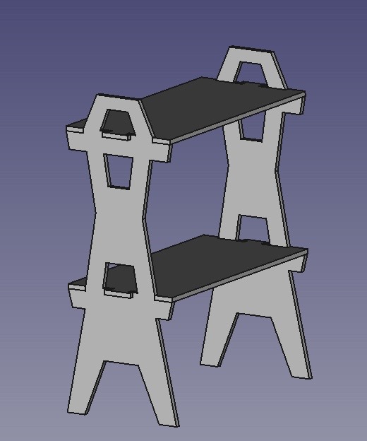
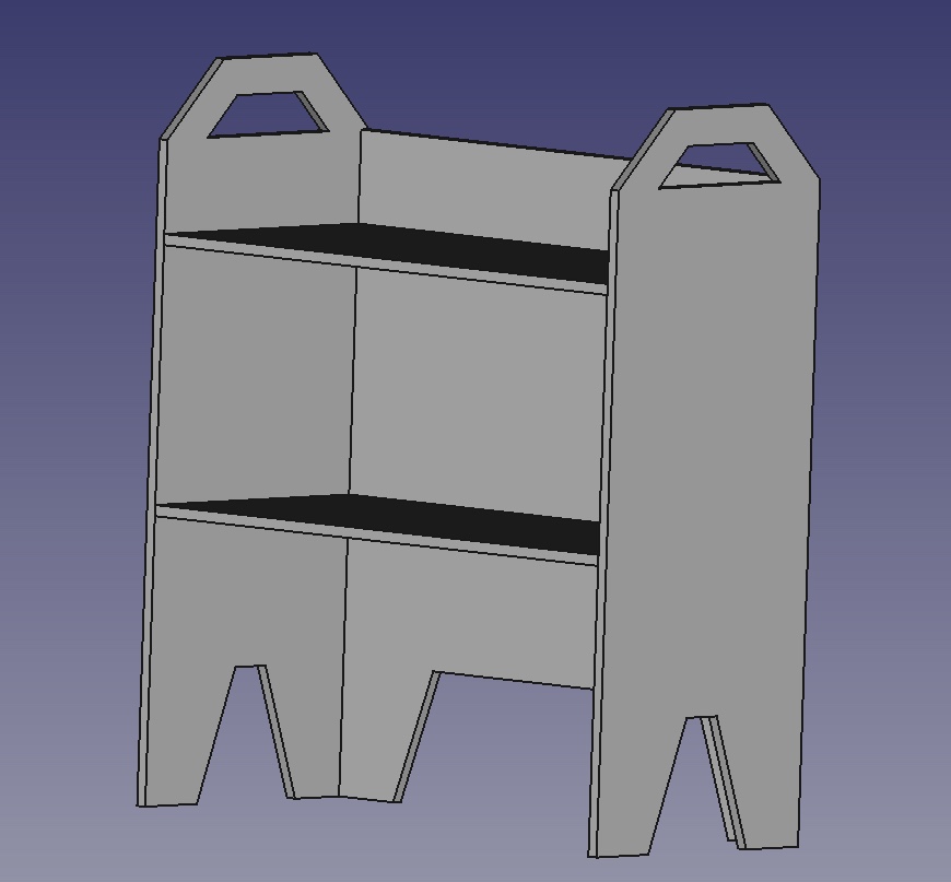
I later learned that this version would not be stable. Although the notches were designed to hold them in place, I was warned by the TA Alfonso that they would likely not be enough to prevent the structure from shearing and taking on a a parallelogram shape. He suggested adding a backing to the shelf as an additional constraint. So I started my design over again. Also, with a backing I realized I would want some finger-joints in my design. But designing them by hand would be a pain I thought! So I started to looke into some tutorial videos on how people designed finger joints in FreeCad.
I tried multiple approaches which was the most frustrating part of the process! I thought that what I wanted to achieve was pretty standard, so I searched up many tutorials on making finger-joints. I was surprised that there weren’t many tutorials that would help me achieve easy-to-update tabs to accomodate for a snug fit.
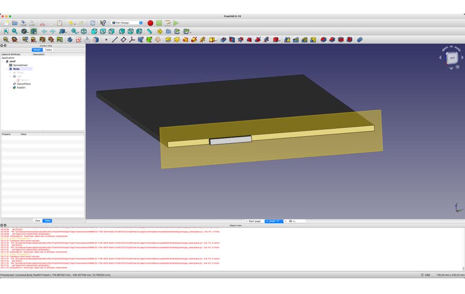
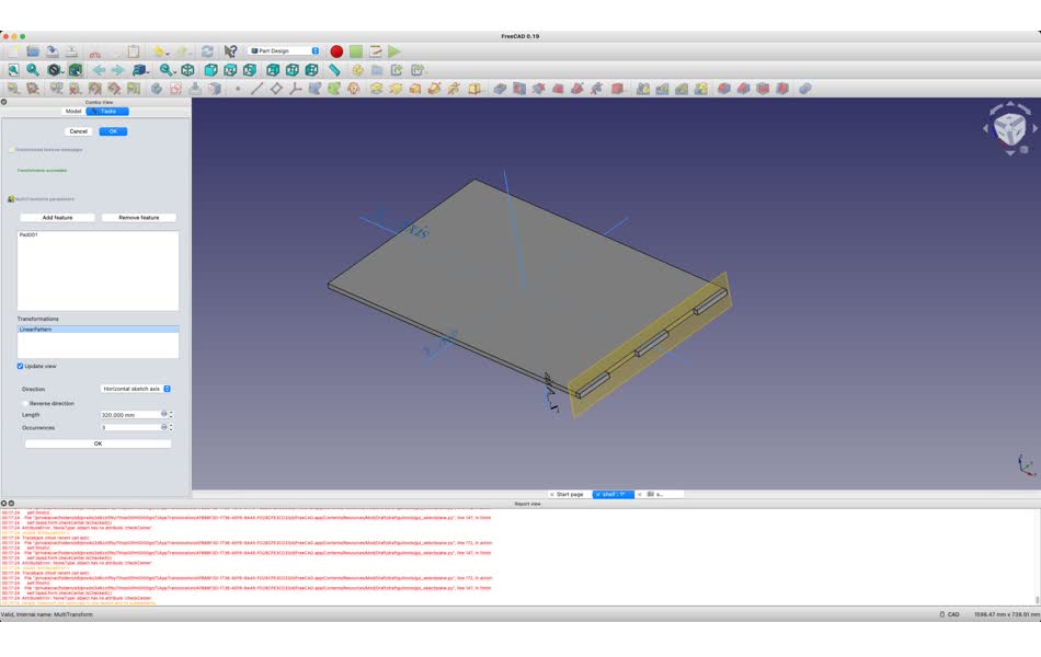
- Designing by parametrically designing a tab, and doing a linear transformation on the tab along the side-wall of a piece
- While it was great that everything could be defined in a sketch, the linear transformation was frustrating. While I could specify the width of each tab and each gap parametrically, I couldn’t wrap my head around how to make sure these would align while using this transformation feature, if the gap and tab width were different.
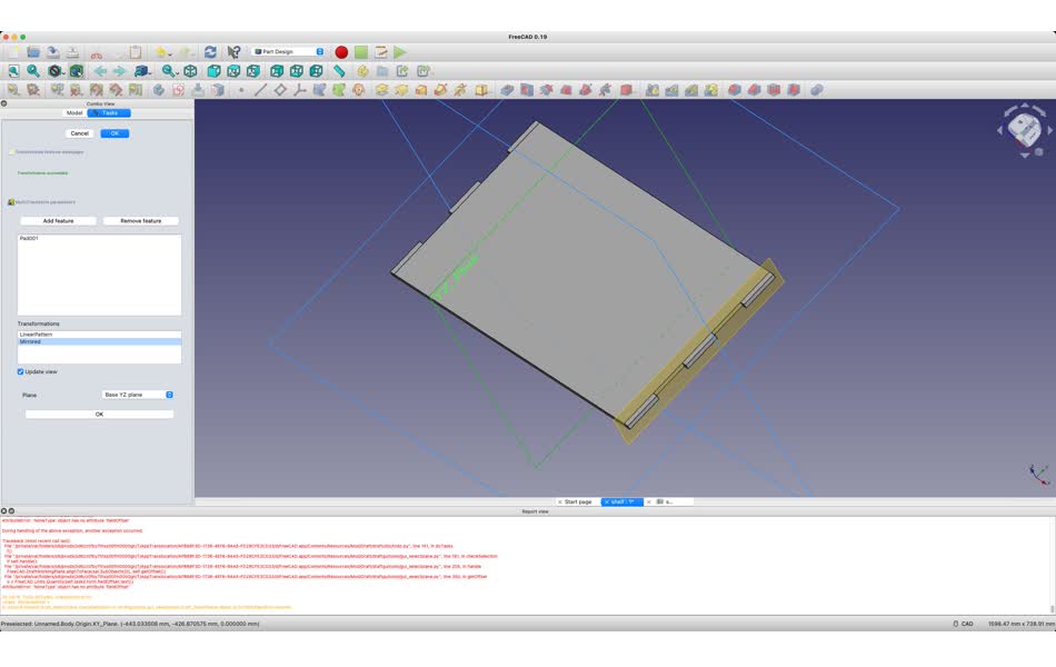
- Using the
LC Interlockingworkbench. (This is ultimately what I used).- At first I thought that the
laserbeam widthparameter would let me customize the spacing between a tab and the gap, that was only partially the case. It did let me make the gap tighter which ultimately helped, but one couldn’t make the gaps larger than the tabs. - This plugin had a lot of handy features, but it also had some bugs. It doesn’t work well with complex shapes (e.g. a geometry with a padding) so after each design, one would have to
make a simple copyof each shape, assemble the simple copies using A2Plus, and then go into the LC Interlocing workbench to add tabs.
- At first I thought that the
Thankfully, after starting this process from scratch for 4 times, I finally came to a design that looked like it might work. However, I still didn’t understand how to use this plugin to really nicely change the parameters of the finger-joings :sad:
As I was unsure if my design had any hope of success, I tried to import my design into Fusion 360 to use the finger-joints plugin that Thaís told me they used. Apparently it’s a huge pain to import from FreeCad into Fusion 360, as Fusion uses a proprietary format .dwg that one cannot automaticallly export to from FreeCad. I tried to get a file converter ODA. Using it, it looked like it worked to get the correct file type. However, when I tried to import the file, the process got stuck halfway and failed. I tried exporting to various other file formats such as .stl, .dxf, and .step. However the finger-joint module required that each pieces that would fit together would be a separate body object in the file tree, which .stl didn’t achieve. With the .dxf I tried to extrude each face to the correct thickness and then apply the finger-joint command, but it would throw errors. The .step file looked the most promising by far, as it actually preserved the different pieces as each being their own body but when I applied the finger-joint command to these, it would also result in a python callback error and would unfortunately not work. I added some finishing touches such as fillets and more notches.
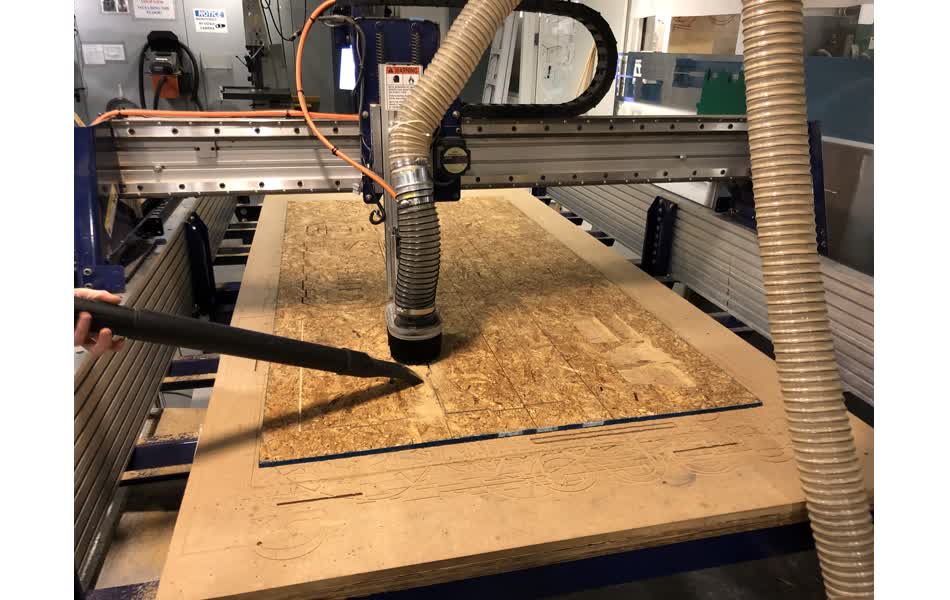
Computer-Controlled Machining
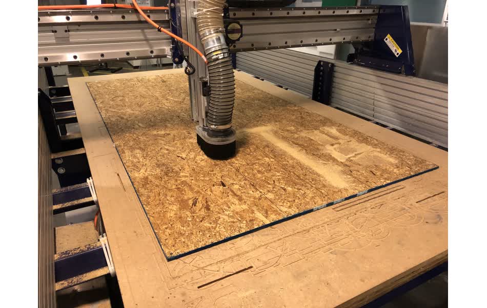
Ultimately, I was running out of time (Ah! ![]() ) so I hoped that my original design would work. I tried a test cut of the finger-joint and the slot that I had designed, and saw that it was ever-so-slightly too tight of a fit. This was a great realization, because as the shop-manager John pointed out, “wood is forgiving” and I would be able to sand things down just a bit to make it work! It was also great that my design was slightly too tight instead of loose so it would stand a chance of keeping itself together.
) so I hoped that my original design would work. I tried a test cut of the finger-joint and the slot that I had designed, and saw that it was ever-so-slightly too tight of a fit. This was a great realization, because as the shop-manager John pointed out, “wood is forgiving” and I would be able to sand things down just a bit to make it work! It was also great that my design was slightly too tight instead of loose so it would stand a chance of keeping itself together.
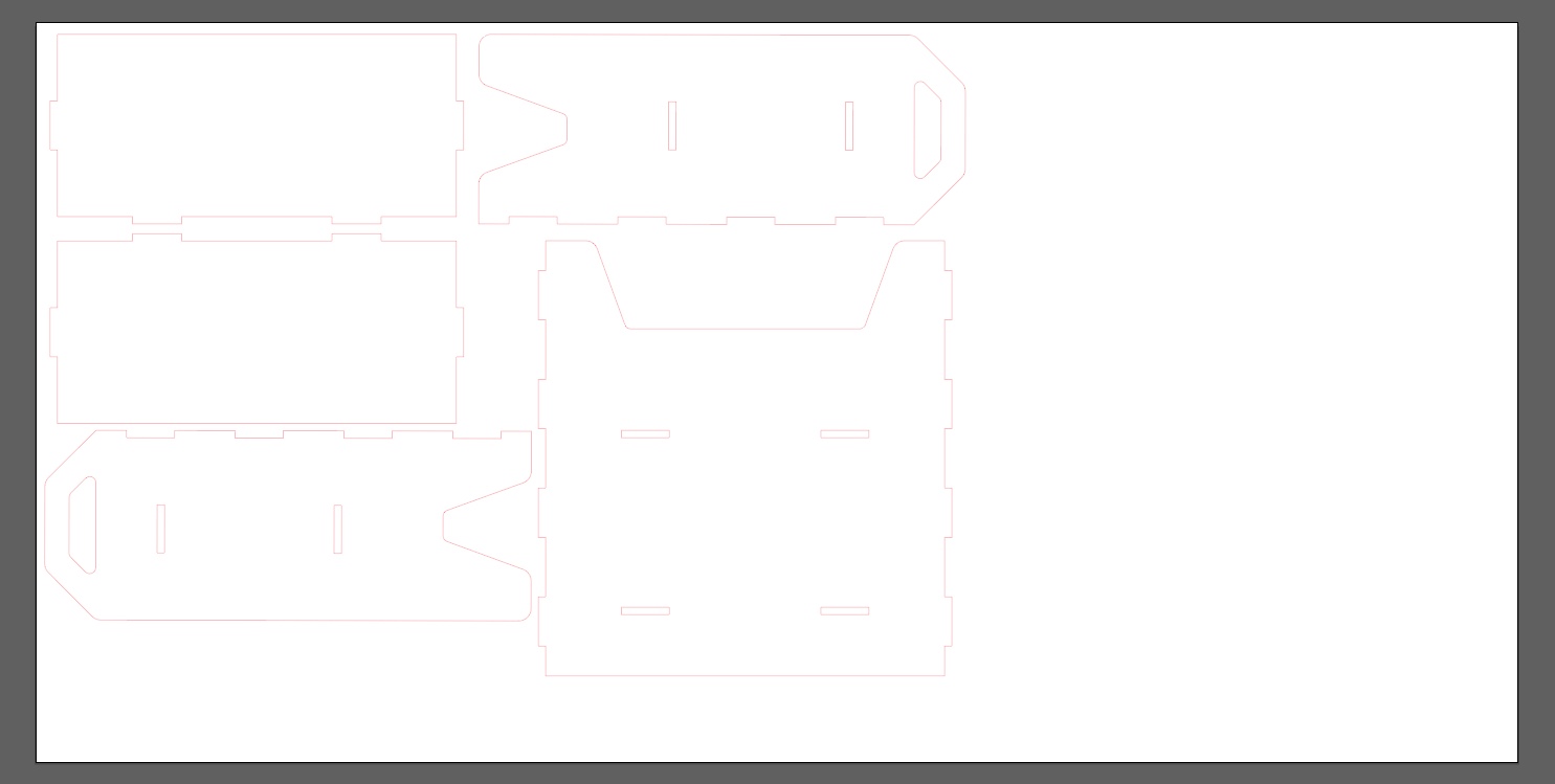
I proceeded to load my entire design file. I made some edits to it by adding the T-Bone fillets to the slot-holes. I ran into an unexplainable bug with the tool to add the T-Bone modifications to the slots on some of the shapes (even Tom didn’t know why), but I figured out a workaround. I could draw a new rectangle over my original rectangle, cut my new rectangle, delete the old one, and paste back the new rectangle. VCarve was way happier with this and let me apply the T-Bone modification to this shape afterwards. The machine was set up to cut along the outside of each shape. And taa-daa, the shapes were born.
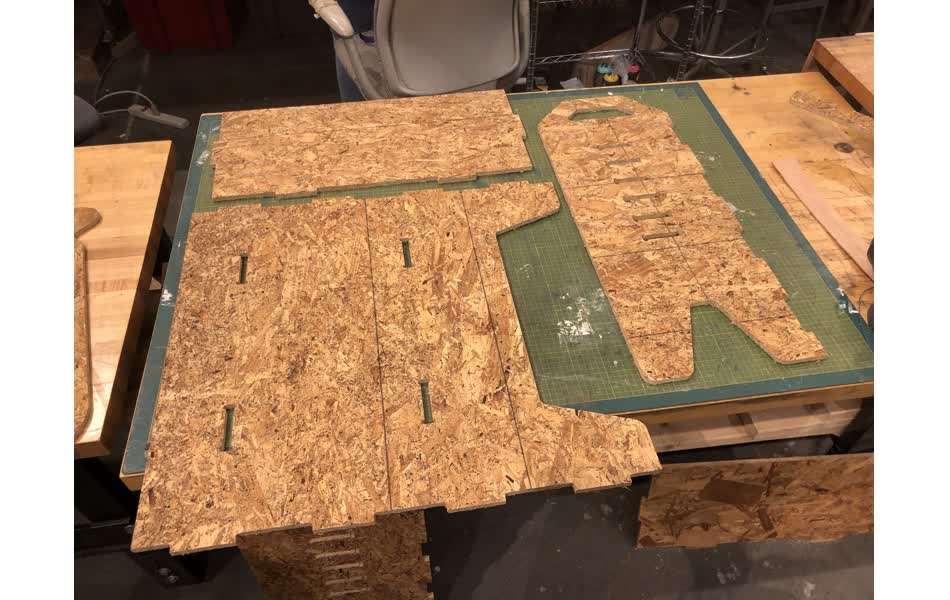
Physical Assembly
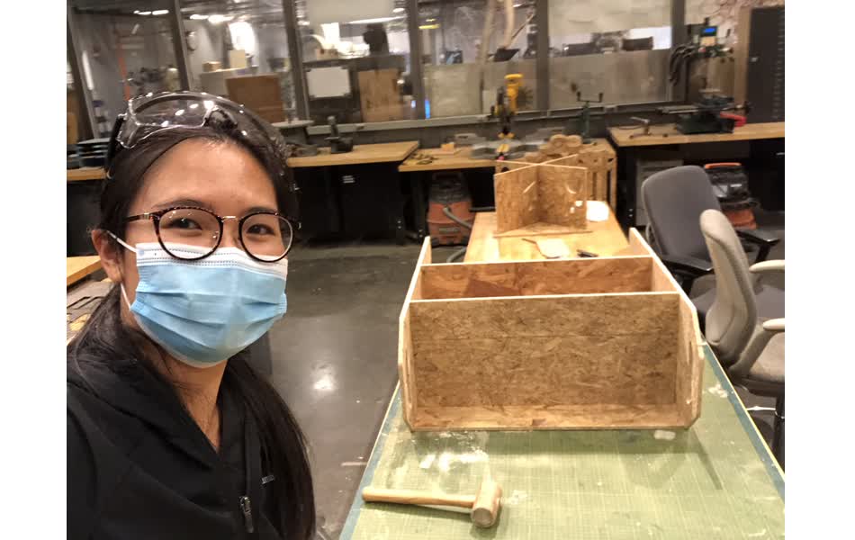
Now it was time to perform some manual labour to the pieces! This was hardwork, but it was also perhaps the most gratifying part of the process.
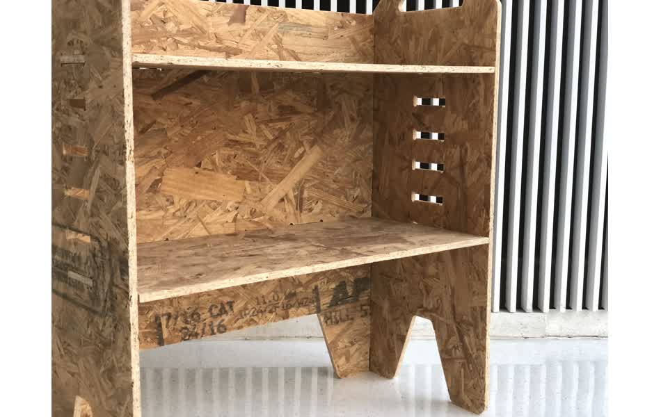
The material was super pokey and unpleasant to touch. I even got a splinter from touching the rough surface! Luckily Thaís lent me a sander, and Jason showed me how to use it properly. I worked over each surface of all the pieces which helped immensely to make the material okay to touch. I then went over each notch and slot with a rasp to sand off a bit of the material to get the finger-joints to slot nicely into each other, and also to get the tabs to fit into the slots for the plates.
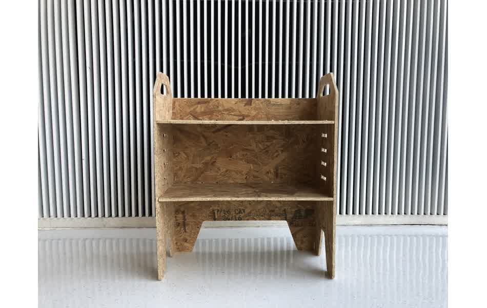
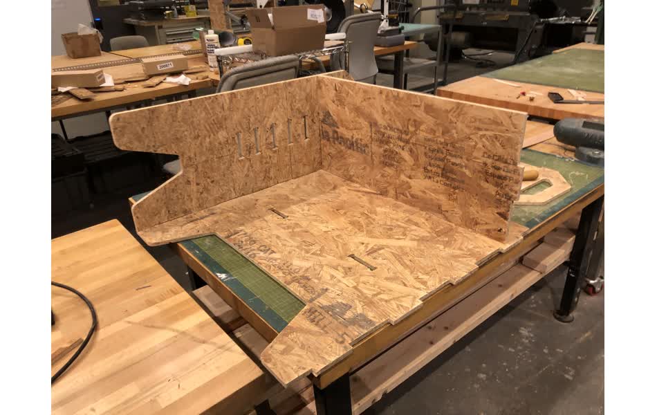
Finally, I put together the shelf and I was so happy to see this thing become a 3D structure that could stand! It did not require any glue or nails to hold itself together. Yay!
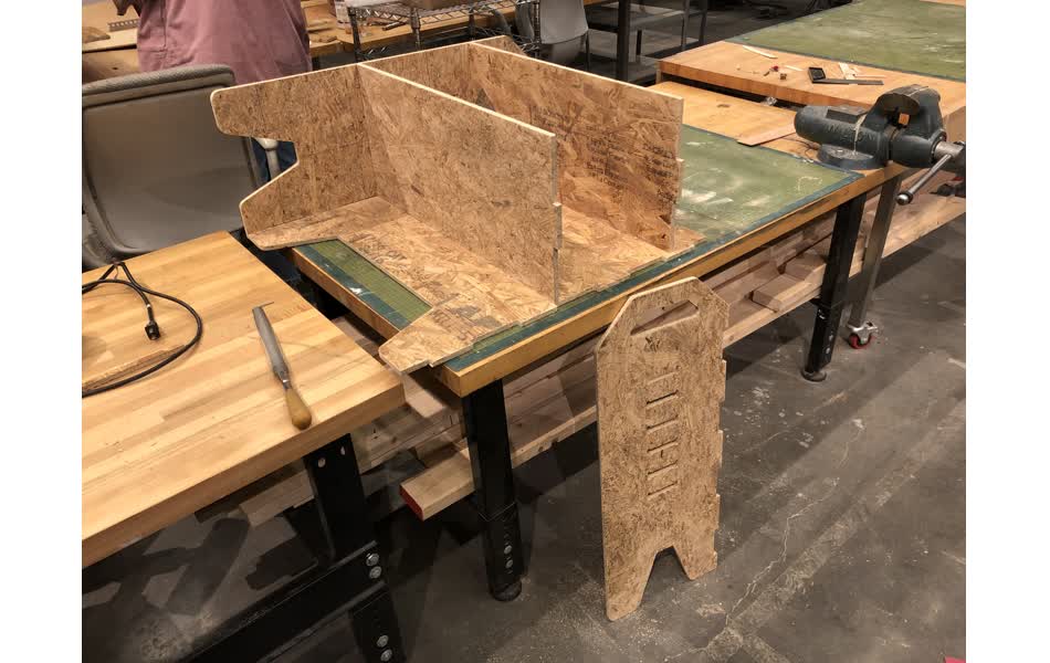
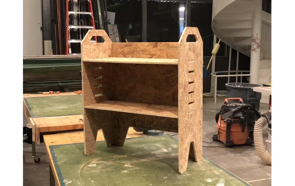
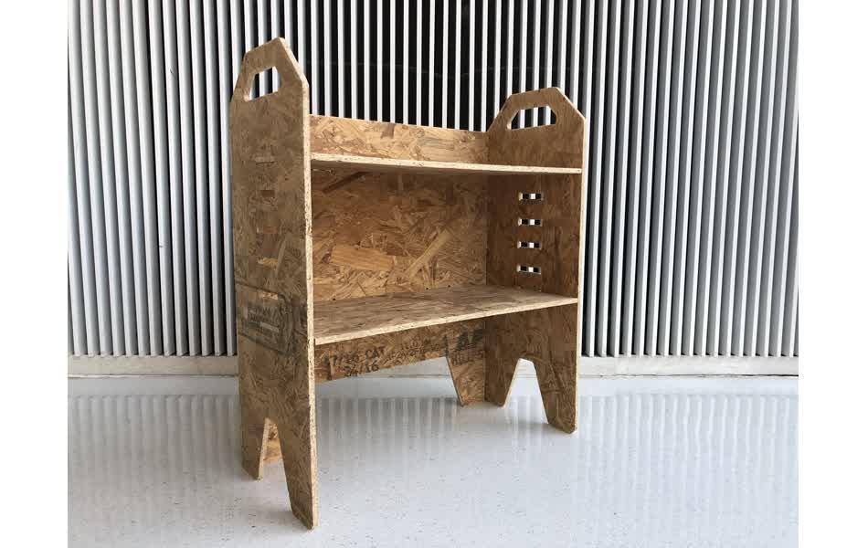
Final Design
Ended up really liking the look! The texture looks neat. Could really be a multi-purpose shelf.