Output Devices
Add an output device to a micro-controller board you’ve designed, and program it to do something. Note that I returned to this activity after Networking week, documented here.
This week, I wanted to work towards my final project. Therefore, my aim this week is to create a separate board that could drive a stepper motor, and which could connect to a separate MCU breakout board. I originally design a board for the DRV8428, but when I arrived in the lab, I realized there were none left. I therefore switched over to using the DRV8436 because Zach was creating a new breakout board for it.
Files
Motor Driver Board Kicad Project (.pro) Motor Driver Board Schematic (.sch) Motor Driver Board PCB Layout (.kicad_pcb) Motor Driver Board PCB Layout - Traces (.png) Motor Driver Board PCB Layout - Outline (.png) Arduino Program (.ino)
Process
Schematic and PCB Layout
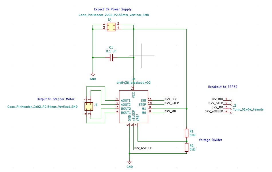
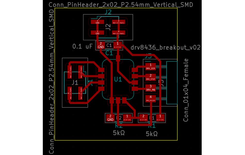
In my case, I wanted to make everything modular. Therefore for this week, I wanted to create a board that would only have the necessary components to run the motor, and be able to connect this board to another board that has the MCU. The schematic was therefore nice a straight forward. As there were few components, it was also relatively straight forward to design the PCB layout. Some difficulties I had was knowing however what values of capacitors and resistors I would need. I took a guess and initially made the resistors in the voltage divider 5k each, and the capacitor a small 0.1 uF.
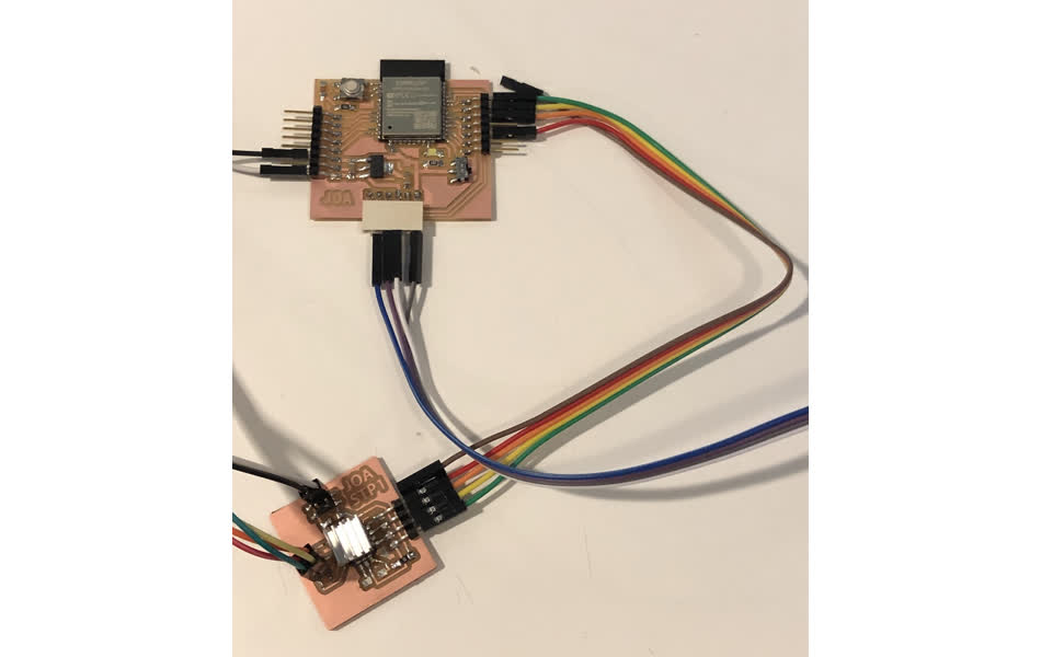
Connecting to the Stepper and the ESP32
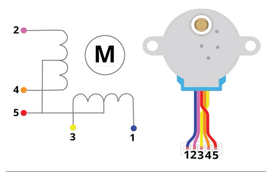
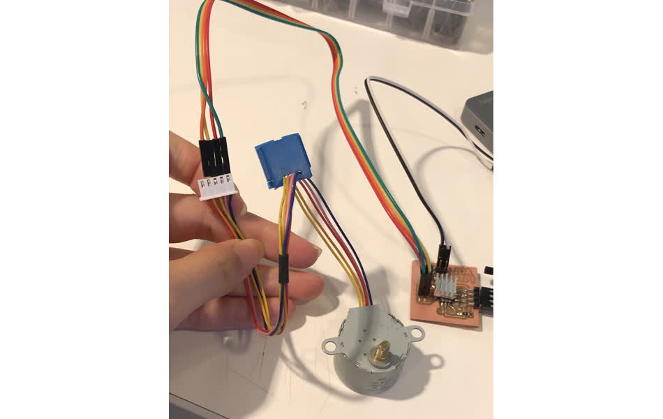
This took some careful work. Firstly, I learned that it’s important to correctly connect the wires to the stepper motor so as not to hurt it. I looked up the datasheet for the BYJ-28 stepper motor and found which wires corresponded with which coils. One important thing to note was that the stepper motors I’m using have been altered by TA Dave. He helped to cut the line that joins the coils, such that the red line is no longer connected. This converted the otherwise unipolar motor to a bipolar motor with a 4 wire input. I then made a table to keep track of how I would hook up the wires from my stepper motor board to the stepper motor. I also had to keep track fo which pins from my ESP32 would connect with the input pins to the motor driver.
Programming the Board to Move the Stepper
There were three important things I learned when trying to get the Stepper to move. Firstly, I needed to consider changing the upload rate to the ESP32. At some point I started to get an error when trying to upload a program to it. When we slowed it down, it was able to successfully load the program.
Secondly, when you plug in the board to a USB power source, it should actually just run. This means that you should simply press the reset board to make it run the script it already has loaded on it/
Thirdly, for the code to control the stepper, I needed to consider altering the delay between high and low signals in the PWM signal. I kept the code very similar to Zach’s template code to begin with. However, I realized that one issue was that my motor could not handle the latter section, nor the speed of the PWM signal. TA Anthony helped me catch this and increased the microsecond delay to 1000. Then the motor started to move!
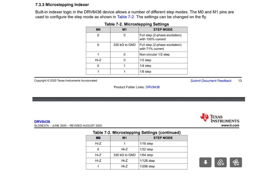
Step Mode Logic
You’ll see that the possibly values for M0 and M1 are as follows:
What do they mean?
- 0 (easy, this is like 3.3 or 5V)
- 1 (easy, this is like ground)
- Hi-Z (this means high-impedance. You can get this by setting the pinMode in Arduino to input) i.e.
- pinMode(M0, INPUT);
- This kind of similar to a floating value
- What this does is use an internal resistor in the ESP32 which will increase the impedance
- Consider the formula V = L di/dt
- 330 kΩ to GND
- This is super literal, connect the pin to this resistor and ground
Why do they have all these possible inputs? To maximize how many stepping modes there are. If the just had 0 and 1, they could only have 4 stepping modes. Now they have 11.
VRef? Do I need a voltage divider?
It depends. As I’m using 5V as a power source, instead of something beefier like 12V, then I don’t have an issue with too much current. My board isn’t getting hot, so clearly I don’t have current issues. However, if I upped the input voltage to 12V, and would directly feed 12V to the VREF of the motor driver board, I will have too much current pumping through. Then I will need to have a voltage divider or a potentiometer to tone down the VREF and limit the current.
Power Management?
So, I am using a shitting USB/TTL converter. The problem with this thing is that although it has a jumper to change from 3.3 V to 5V, this is buggy. What it SHOULD DO:
- Not alter the logic level of TX and RX
- Alter the VCC output from 3.3V to 5V What the shitty thing is doing:
- Changing the logic level of TX and RX to 5V, instead of keeping it at 3.3 V
- Also changing the VCC output
A better option is the expensive cable, which would have the expected behaviour.
Oscilloscope Learnings
- You don’t want to create a short between 3.3V and GND! You will have a lot of current running and make things (I guess my board if the current runs through it) very toasty
- Some things about reading an Oscilloscope. You want to make sure you can find a place to cleanly attach the banana cables to your board.
- YThe viewing grid on the oscilloscope will give you a sense of the units, so if it’s drawing a graph you know what voltage values are being read
Troubleshooting / Debugging
I found that after trying out my connections, the motor didn’t want to move! I spoke to the TA Anthony, who kindly helped me debug my board to the point that it worked. I document my learnings below:
Process
- Checked the motor - is it bipolar? Then the coils should be connected.
- A+ connected to A-, B+ connected to B-, and A and Bs are not connected » TRUE
- Checked the connection from the motor driver board to the wires
- these were broken (according to the multimeter). Therefore fix the soldering on the motor driver board, add more solder for a healthy connection. With a multimeter, could see this was true.
- After fixing the connection, the motor made sound. It gave off a low-volume, high-pitched screech sound “eeeeeeee~”
- Started to check the power. I said I am feeding it 5V input.
- Checked the 5V line and no problem there
- Checked the GPIO Pins with an oscilloscope
- The GPIO Pins were operating as expected (matching the behaviour I instructed the ESP32 to follow)
- E.g. DIR = HIGH = 3.3V ash output
- M0 = LOW = 0 v ash
- NSLEEP = HIGH = 3.3 V ash
- STEP - was giving off HIGH and LOW pulses…
- The GPIO Pins were operating as expected (matching the behaviour I instructed the ESP32 to follow)
- Since the motor was doing a high-pitched squeaking sound, the next guess was the code
- Removed the change timer loop that will make it sounds like a siren…
- Increased the delays to 1000 microseconds (= 0.001 second)
- THIS WORKED! The motor actually moved.
You can see that the motors could move in the final project, here.