Input Devices
Measure something: add a sensor to a microcontroller board that you have designed and read it.
Process
For this week, I decided to create a breakout board for the SAMD11C14A microcontroller. TA David Preiss reminded us that this is a possibility, which would also make a subsequent project easier to do if we can plug and play with different inputs and outputs. Therefore, my mission became to make a breakout board for the MCU, and a second separate board with a sensor.
- Design and make a SAMD11C14A breakout board
- Design and make a sensor board
- Connect the boards and write a program that make the boards talk
Files
SAMD11C14A Breakout Board
Breakout Board Kicad Project (.pro) Breakout Board Schematic (.sch) Breakout Board PCB Layout (.kicad_pcb) Breakout Board PCB Layout - Traces (.png) Breakout Board PCB Layout - Outline (.png)
Hall Sensor Board
Hall Sensor Board Kicad Project (.pro) Hall Sensor Board (.sch) Hall Sensor Board (.kicad_pcb) Hall Sensor Board - Traces (.png) Hall Sensor Board- Traces (.png)
Code
MCU Breakout Board
JTAG Connector
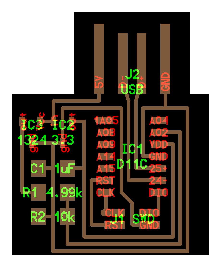
Unlike my previous Wall-E board that used the 4-pin JTAG connector, I decided to make a new board design with a 10-pin JTAG connector. I wanted to do this because I know the CBA lab has the Atmel-ICE programmers readily on hand. It was tricky to avoid too many jumps given that I wanted to break out all the pins, and also have the USB port. Eventually, I settled on using a couple of 0Ω jump resistors to help myself out.
Board Design Recommendations 
Some things I’ve been told in designing a board
- The capacitor should be as close to the MCU as possible

- The D+ and D- lines from the USB should ideally be parallel (Whoops, I think by using the jump resistor I didn’t really achieve this on this design.)

- Next time, I should make a double-sided board, where the bottom plate is ‘GND’, and have through-holes to get my components to connect to it when needed.
- The bottom plate as ‘GND’ can also help to stabilize signals apparently
- Apparently double-sided plates tend to be less bowed, which can help with successful milling.
MCU Pin Layout
To make a good breakout board, I needed to keep track of the MCU pin layouts! I referenced this image from here. What I wanted to keep the physical location of the pins in mind to minimize the crisscrossing of lines. 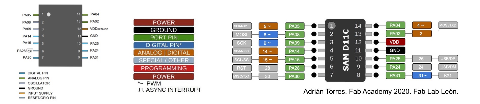
Breakout Header Pins
I was initially unsure what components to use for the breakout pins. I finally figured out that I could use the fab library footprints for connectors. I chose the female horizontal connectors and 2.54mm pitch. This footprint was good as it also had an outline to show how much space you should provide on your PCB layout so that the headers have a stable surface to sit on. I learned that the hardware I wanted is typically referred to as FTDI headers, or just headers. Cables that can be used to connect headers are called jumpers.
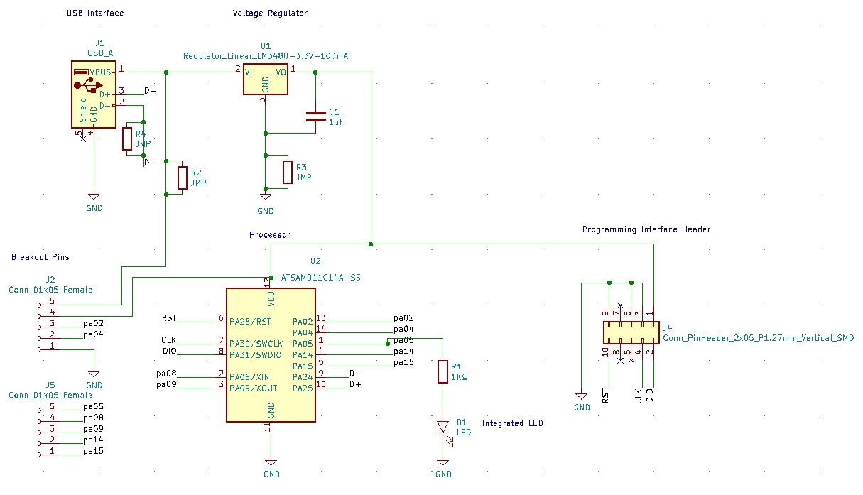
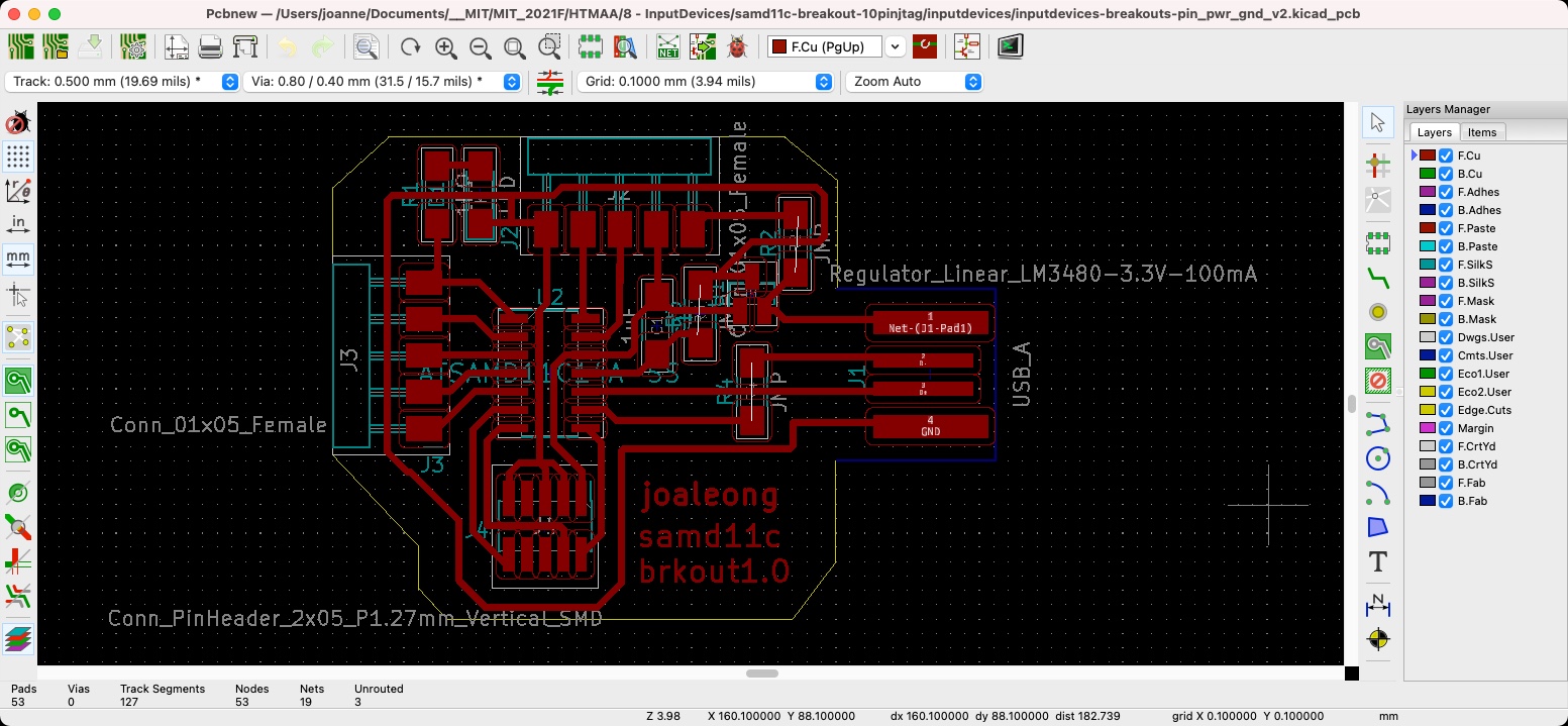
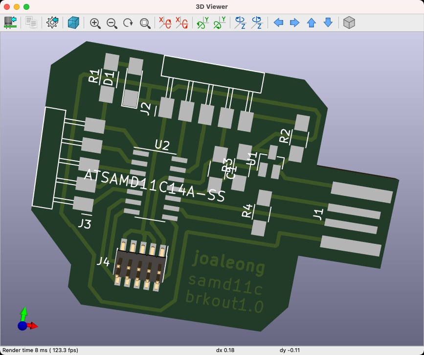
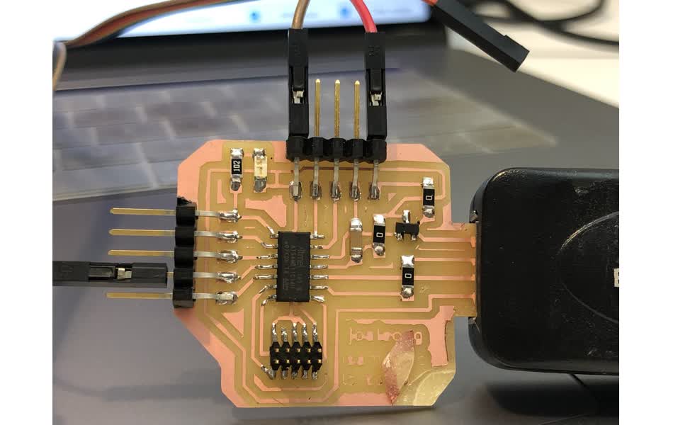
MCU Breakout Board Design
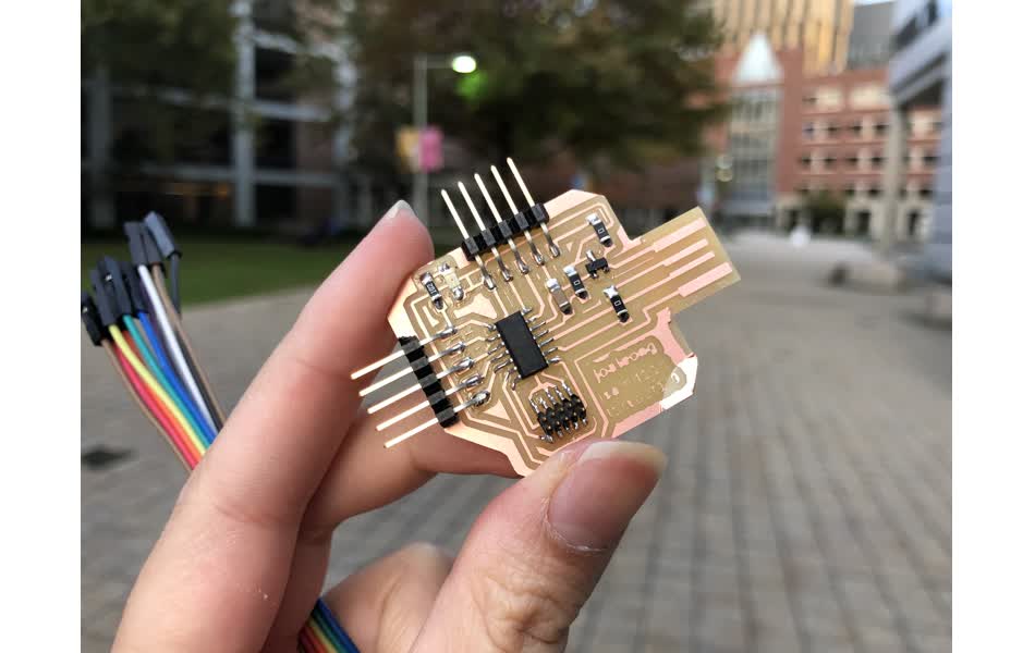
Here are the designs I got to with the schematic and the layout. I included an LED on the main board, because it’s always helpful for checking if the board is functional. I also (thankfully) thought to have a pin to breakout the power (5V and 3.3V), and a ground line for any peripheral components in the future. You can see that the board got chipped when making it. The tape that was available to use was too strong! When trying to pry the cut board off the sacrificial one, the tape held it in place so hard that I ended up cracking the board instead of removing it. David helped me use an exacto-knife blade to separate my board from the bottom plate ![]() . It is ironic that my breakout board was hard to break out.
. It is ironic that my breakout board was hard to break out. ![]()
Programming the Board
This time TA David helped me with the programming using the Atmel-ICE device and the Microchip Studio software. The software only works on a Windows machine. With it installed, you can plug in your device. Make sure you have downloaded the samd11c14a.bin file (you can get that here), which you will need to select to upload the correct bootloader. This bootloader is superior as it gives you a lot of access to the MCU’s pins. It helps to ensure that your device knows to recognize USB input. Note that you may accidentally plug in the JTAG connector upside down. You will see if you plugged it in with the correct orientation when you see the ‘Target Voltage’ be the expected amount for the MCU (this one is 3.3V). This tutorial from FabLab kannai is very helpful to following along. The screenshot they took here is useful.

Hall Sensor Board
I decided to start with a Hall sensor given David’s recitation and the example from Neil available on the class website.
Studying the example
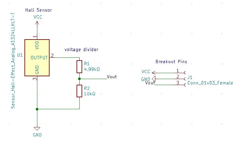
I looked at the hello.mag.D11c example for a magnetic field input for the SAMD11C. Studying the traces on the board, I noticed that the Hall sensor (SOT23) needs a 5V input. I also noted that the circuit uses a voltage divider to reduce the voltage of the output to the 3.3V range for the MCU. This was extremely handy information, which I could re-use in the design of my sensor board.

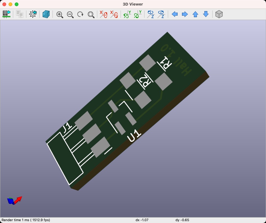
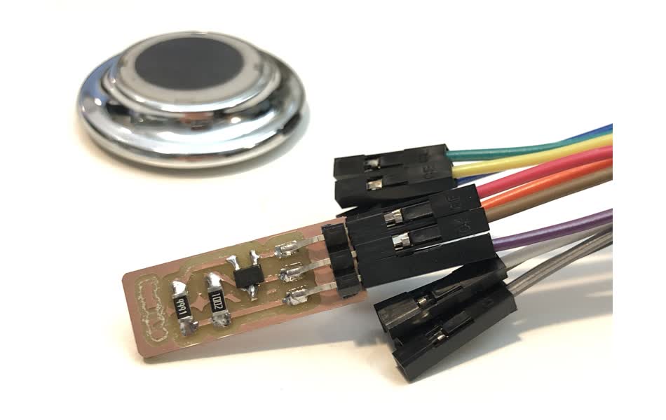
Hall Sensor Board Design
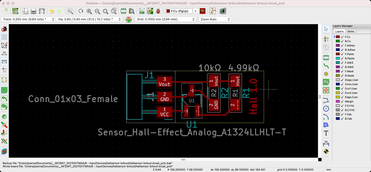
This is the schematic and layout I came up with. Here, I had pins for the 5V Input, Ground, and the Vout pin from the sensor that would go back to the MCU. I designed it to be about as most compact as I could, which was satisfying. However, as you might notice, I originally forgot to change the trace-width and clearance parameters while laying out the board. This meant that later I’d have to redo the layout with thicker lines and mill and stuff the board all over again. ![]() It feels to me that there are many little details to keep in the forefront of your mind so you don’t make mistakes!
It feels to me that there are many little details to keep in the forefront of your mind so you don’t make mistakes! ![]()
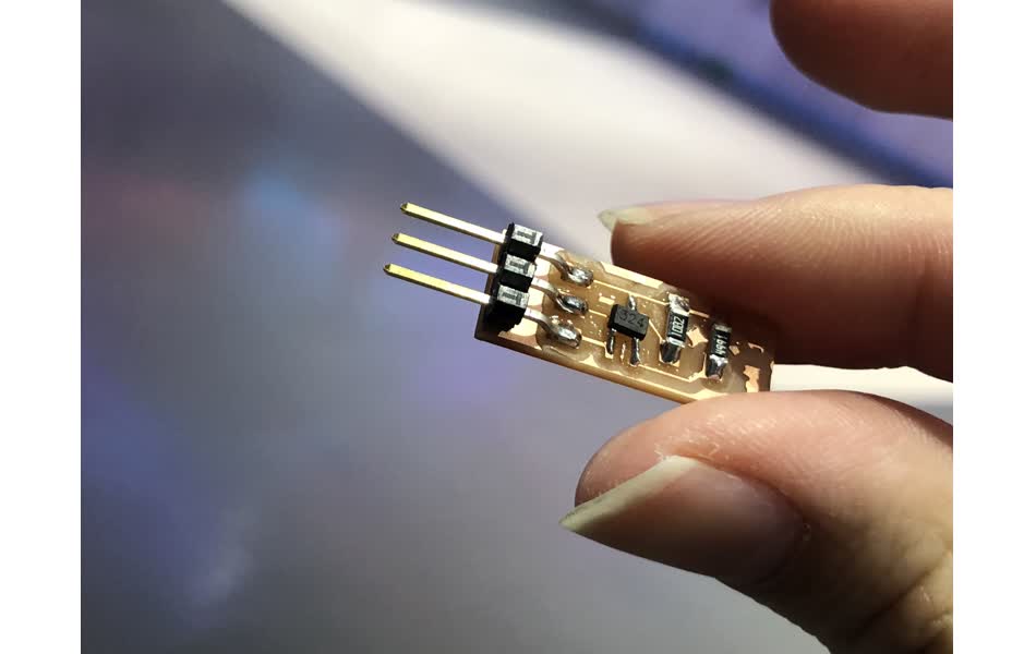
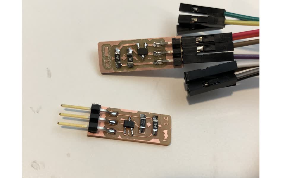
Final Output
When I proceeded to hook up the sensor to my MCU board, I noticed that the signal wasn’t changing when I brought a magnet closer to it. Uh-Oh. After a while of experimenting with the code, I had the feeling my hardware was the problem and not the code. On inspecting my sensor board, I realized the traces were VERY skinny, and I had heard from my classmates that this often led to the board not working. So I went back to the hardware dungeon alone late at night to redo the sensor board again. It was a little eerie, but nothing bad happened thankfully. My new sensor board was born, and very thankfully, it worked!
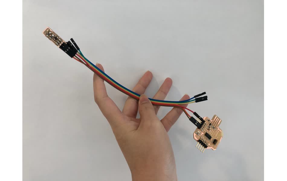
Here is a video where you can see the sensor working! ![]()