Networking and Communications
Design, build, and connect wired or wireless node(s) with network or bus addresses
Process
As for my final project I would like to make a portable device, I would like to be able to communicate with it wirelessly. Talking to Dave, our TA, he suggested I use the ESP32 as it would be capable of a wireless connection and also has plenty of GPIO pins which I could use to drive Stepper Motors.
Files
ESP32 Breakout Board
Breakout Board Kicad Project (.pro) Breakout Board Schematic (.sch) Breakout Board PCB Layout (.kicad_pcb) Breakout Board PCB Layout - Traces (.png) Breakout Board PCB Layout - Outline (.png)
Code
Code - Simple Web Server (.ino) Code - Web Server with Button (.ino)
Equipment
- USB/TTL converter
- ESP32-WROOM-32D
- Male-Female jumper ribbon cables
Board Design and Fabrication
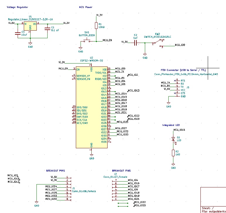
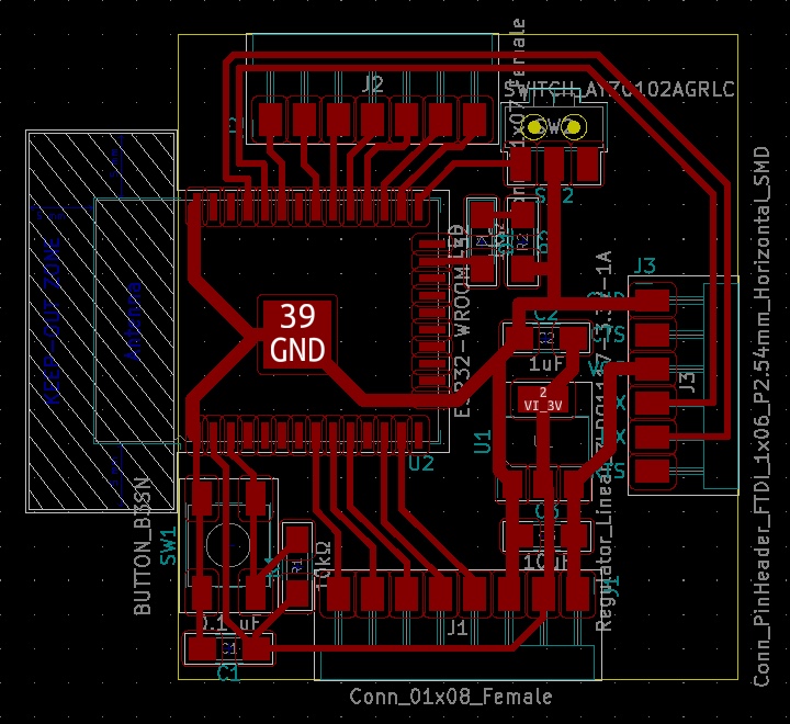
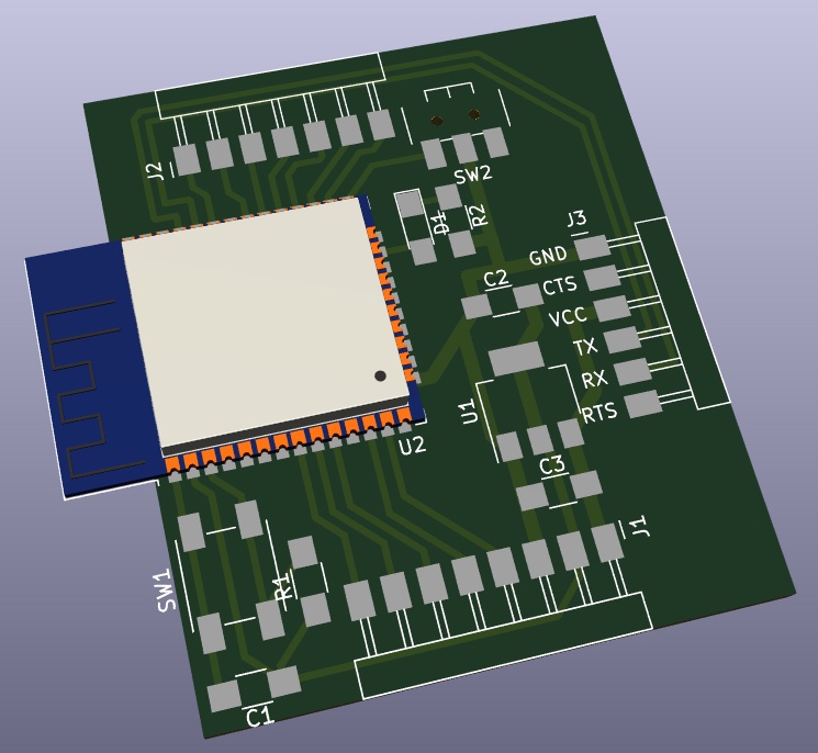
So far I had only used the SAMD11C microcontrollers. Therefore I needed to do some learning to get off the ground with the ESP32. Anthony, one of our TAs, noted that the ESP32 has a lot of quirks. Although it has many general purpose input/output (GPIO) pins, these pins may have some strange behavior since they are overloaded. I referenced this website heavily to learn about which pins I should break out for inputs and outputs. I originally planned to breakout more pins, but wanted to avoid crossing over lines and I also wanted to be able to braek out the GND, and 3.3V and 5V PWR pins. I used Neil’s example as a basis for the design ` hello.ESP32-WROOM` found here. I settled on a final design that looked like this. I made the traces thicker for the GND and PWR pins with the intention that they could also be used to power future motor drivers.
Milling
While I have already milled a few boards over the course of this class, I ran into two new problems with milling.
My first issue was that although I used the fab footprint for the ESP32-WROOM-32D, it turns out that the pads were too large for the 1/64” endmill to mill out. As such, my first board was fabricated flawlessly, except for the pads not being cut out. Therefore, I had to revisit KiCad and use the footprint editor to change the pads. The pads were 0.9 mm thick. In the properties editor for each pad, I changed each pad to be 0.6mm thick instead, such that the spacing between them would be wide enough for the mill to pass through. I saved the new traces and outline to fabricate again.
The second problem I had was that the tape was too weak, and when I was milling the second board, the sacrificial board dislodged from the foundation. This meant that the board was not completely cut out. I tried to cut the board out with an exacto knife and later a rolling blade. Eventually it worked, but my hands were super tired after this. While I was busy cutting this board out by hand, I decided to run my milling job for a third time…
I set everything up again. I stuck down the sacrificial board anew, and mounted a fresh board to mill on. The third time was the charm. This process overall unfortunately took a lot of time.
Stuffing
There were some new components to take note of that I haven’t used before, aside from the ESP32. The 3.3V 1Amp regulator has four pins instead of three. Although the top pin is a duplicate of the output pin in my case. This regulator also benefits to have a bypass capacitor to help it give a steady signal. There is also a switch component that was labeled as ‘prog run’ in the example. I later found out i should have drilled holes for the bumps on the back of the component, but ultimately this wasn’t a big deal. Only now that my switch is mounted at a slight angle.
Connection and Programming
I needed to jump through quite a few hoops to make this work.
Somethings that are good to note:
- Firstly, the ESP32 already has a bootloader on it, so we don’t need to load one onto it manually.
- The ESP32 doesn’t support a USB protocol out of the box. Therefore, we design a board with the FTDI connector instead, and need a USB/TTL converter or cable so that we can make our computer talk to the MCU.
Getting the FTDI Driver
The computer has to recognize 2 things.
- The FTDI converter/cable
- The ESP32.
We can first check the Macbook sees the FTDI converter by checking “System Information” or typing the following command in the terminal ioreg -p IOUSB -l -w0. In my case, I have a converter with chip FT232RL so this will show up with that name when it alone is connected to my USB port. Then, we need to get an FTDI virtual COM port (VCP) driver so the Macbook will see my board when I connect it via the USB/Serial cable. I went to get the driver from here and downloaded the one for Mac OS X10.15 and macOS 11. The driver installer right now is in Beta and has a quirk in that you have to throw the installer into Applications before you can run it. You also need to go into System Preferences and give it special permission to run it. And then you must restart your machine before a port will show up in the Arduino IDE for your ESP32. You can also type this command into the terminal to see if your ESP32 device is connected ls /dev/cu.*
Once you have the driver and the device is recognized, you can find it in the Arduino IDE. I selected the board to be `ESP32 Dev Module’.
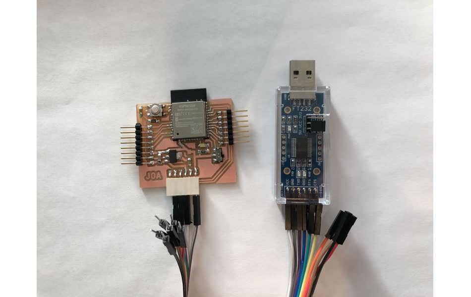
Connecting the USB to TTL Serial Converter to the Board
Regarding the FTDI connector, I make use of the pins: VCC, GND, RX and TX. I ignored the CTS and RTS lines, which I didn’t have to connect.
To connect it to my board, I connect it directly. As in:
- VCC –> VCC
- GND –> GND
- RXD –> RX
- TXD –> TX
Steps to Load a Program and Run It
I needed to understand how to use my board, based off of Neil’s ESP32 example.
These steps are IMPORTANT :
- Flip the switch so that the ESP32 is ready for a new program to be loaded.
- Press the reset button.
- From Arduino IDE, compile and load program onto the board.
- Flip the switch back off.
- Press the reset button again. Now the program should run.
Networking
So the ESP32 can serve as a server! This is cool. On the server, I host a website, and then reach it from my computer’s browser at the IP address. On the website, I can click a button that will send a command to the ESP32 to turn the integrated LED on my board on and off. It works! This was based off the an example found here So gratifying to see it run. ![]()
Note: In this video I forgot to update the website to say GPIO15 (the pin I used for my integrated LED) instead of GPIO26.