Computer Aided Design: The Three-Body Problem
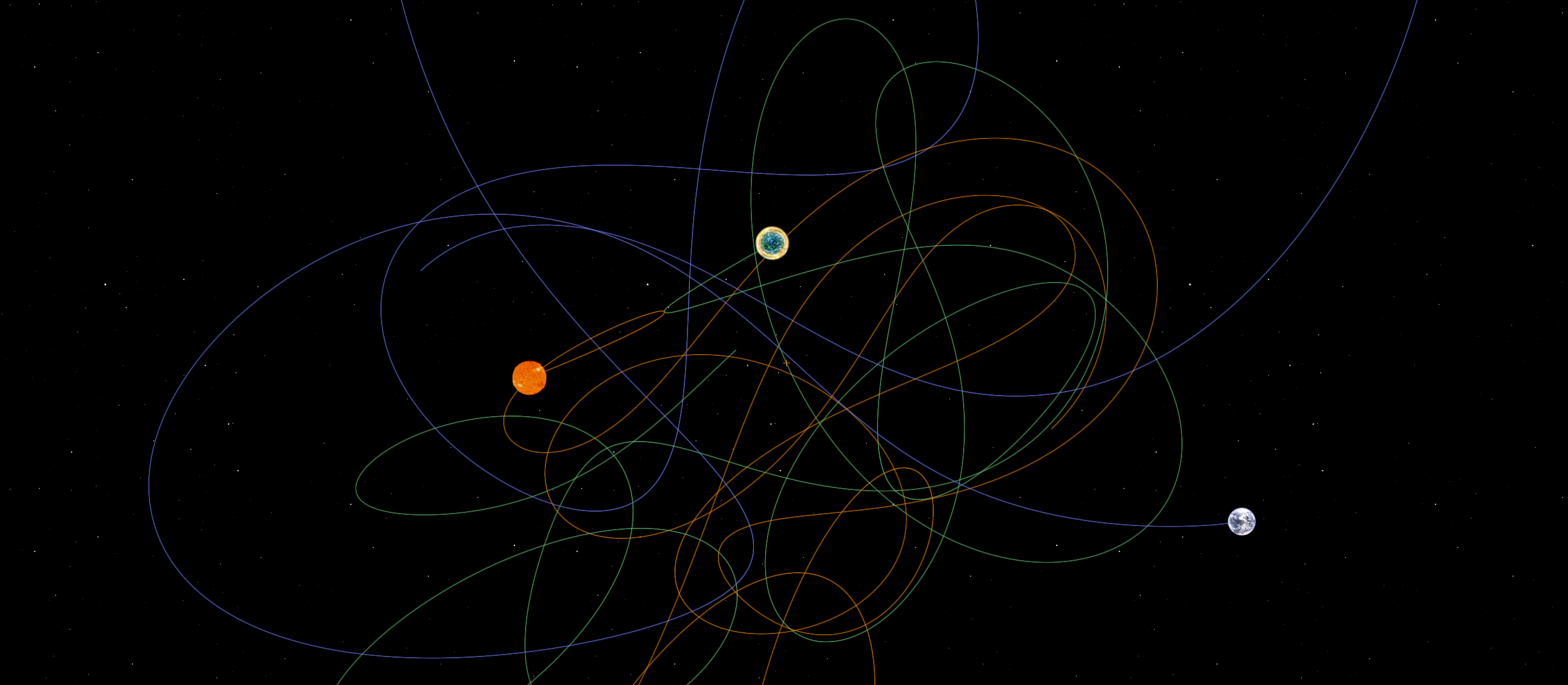
"It’s just like we guessed long ago: The three-body system is a chaotic system. Tiny perturbations can be endlessly amplified. Its patterns of movement essentially cannot be mathematically predicted." - Liu Cixin, The Three-Body Problem
Introduction & Concept Development
After a while of soul searching to figure out what I was interested in making, I have an initial idea for a final project for the 2024 HTMAA course. The idea is simple and should be both challenging and rewarding to make. I want to make a physical model of the three-body problem. In celestial motion, the three-body problem is a true chaotic system which has a limited number of stable solutions. Taking inspiration from Liu Cixin's trillogy "The Three-Body Problem", I want to create a desktop display that models the movements of celestial bodies in a chaotic system.
To achieve this, I'm taking inspiration from the MIT Media Lab's Tangible Media Group. About a decade ago, they unveiled a dynamic tabletop that had a grid-like pattern of actuators. This kinetic tabletop was capable of moving objects, like a ball, around in patterns defined by hand gestures of the user. This is neat, and can serve as a foundation for this concept. A series of 1 DoF actuators can be arranged to create a grid that can then be used to move three "suns" in patterns that are determined mathematically based on user inputs. Several challenges arise with this: (1) to have sufficient granularity, I will need to make a lot of actuators, (2) this will cost a lot, and (3) there will likely be emergent characteristics with a bunch of electronics placed near one another that will be challenging to predict.
These challenges feel manageable right now, so let's dive in with an initial concept drawing.
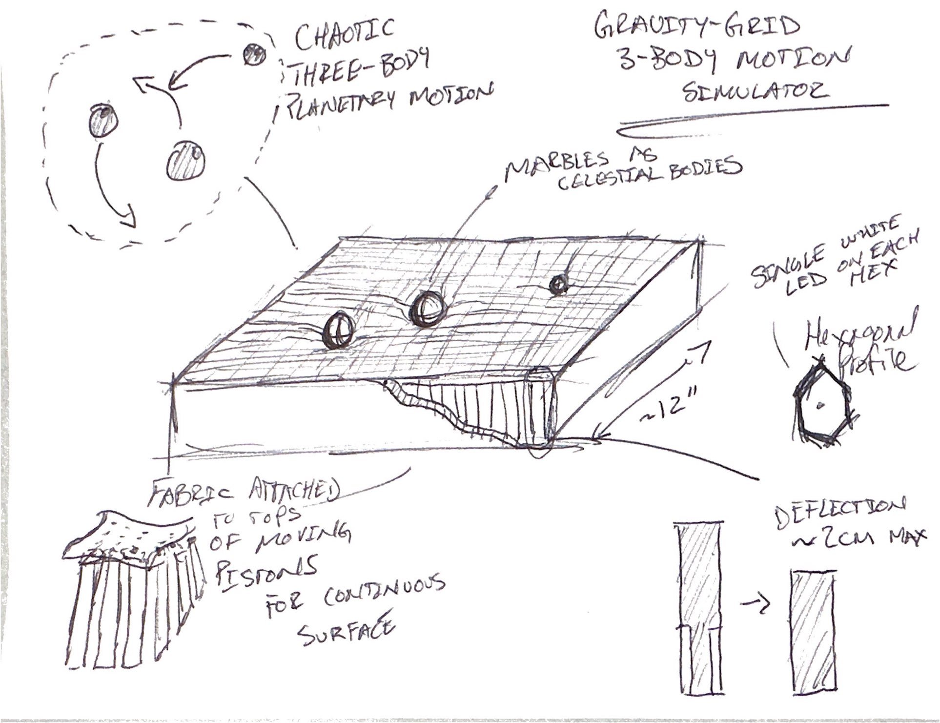
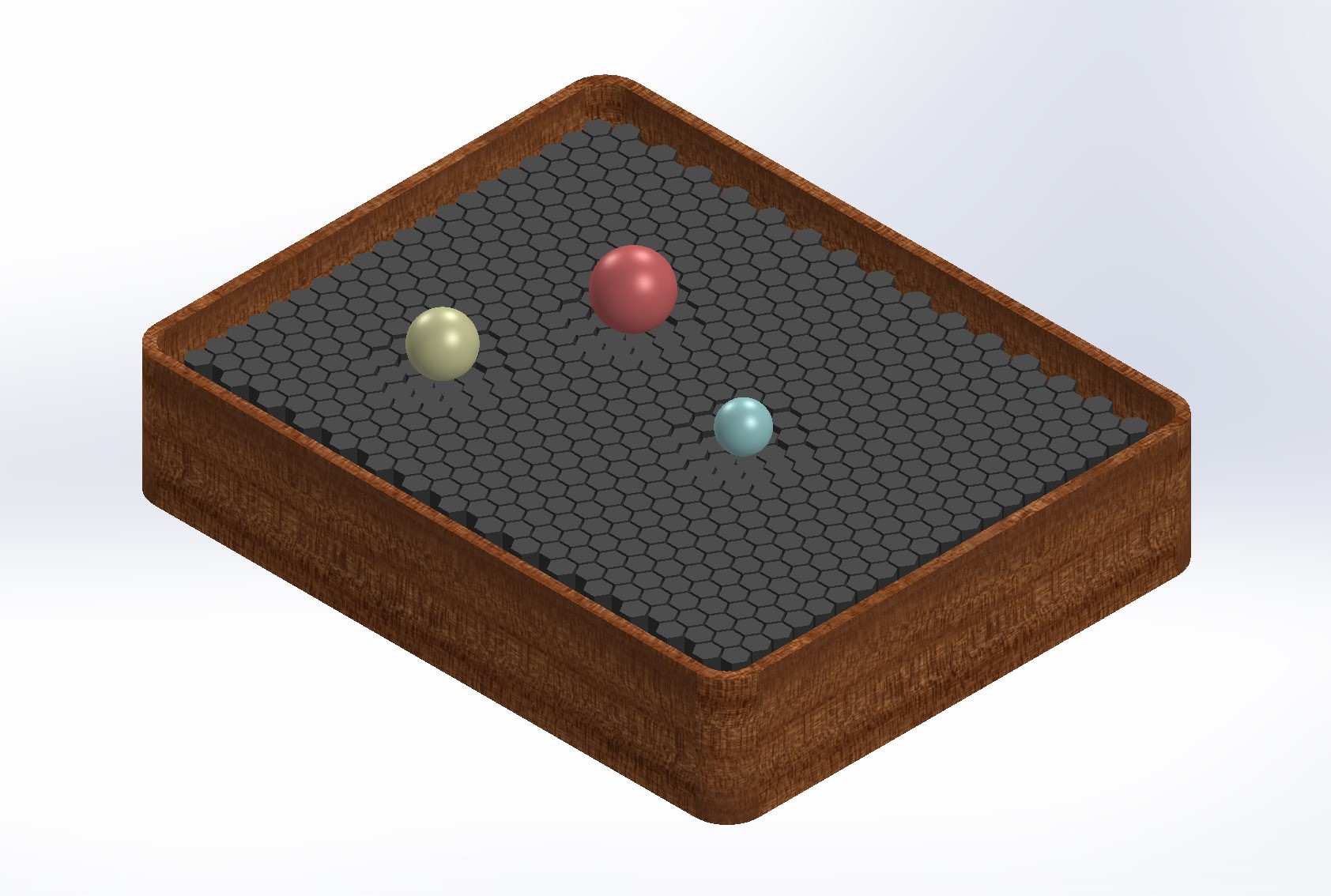
I opted for a hexagonal shape to the actuators becasue I will want to make a series of "gravity wells" which will appear to be funnels. We can get away with a coarser granularity for circles when making them with hexagons. Additionally, the idea at this stage is that the device will be about a foot in both the x and y directions, and maybe a few inches in the z. The pistons will be covered with a fabric so as to conceal the actuators and give the appearance of a seamless bend in the space-time fabric around the suns. There is a concern about power consumption for this device, but since only a dozen or so pistons will be actuated at any given moment (only the onces needed to create the gravity wells), this should hopefully reduce the power cost. Additionally, the actuation depth is small, so this should help too.
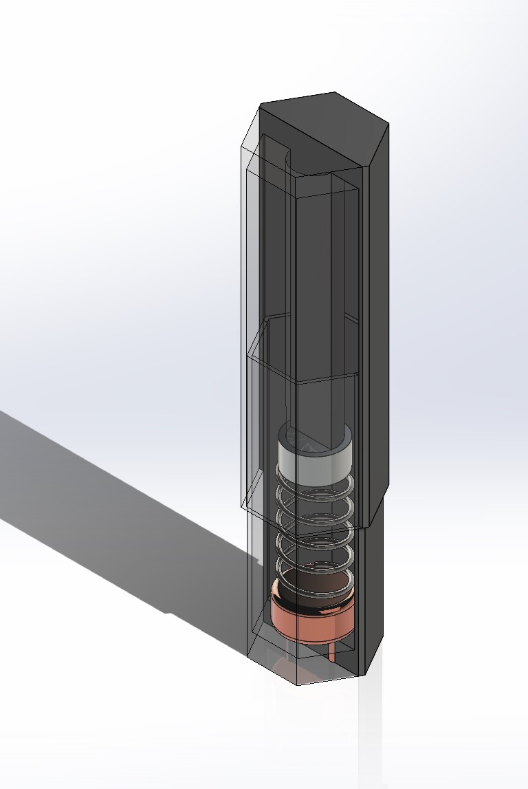
With this, let's start by defining the technology concept for the 1 DoF actuator. The needed movement is only about a centimeter, so this will reduce the size of the actuator itself. I couldn't find any COTS actuators that met my specifications and budget (remember I will likely need a few hundred of these things), so I think I will need to make one myself. A tricky thing is that the nominal state for the actuator must be in the extended postion - i.e. against gravity - and the actuated state must be depressed. This constraint points to an interesting solution. The principle is simple: combine a permanent magnet with a spring and an electromagnet - when current is applied to the electromagnet, a magnetic field is activated and causes the spring to compress. Voila! Actuation.
Concept CAD
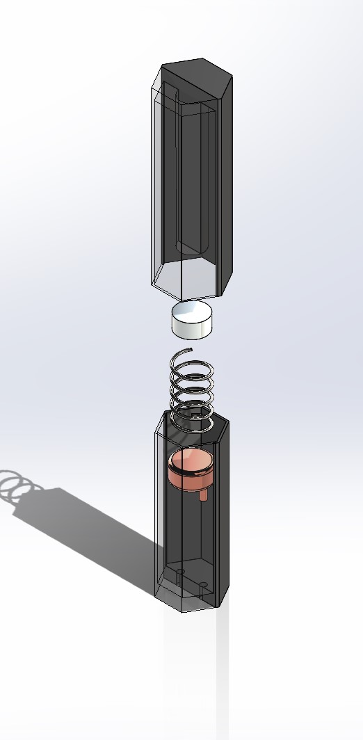
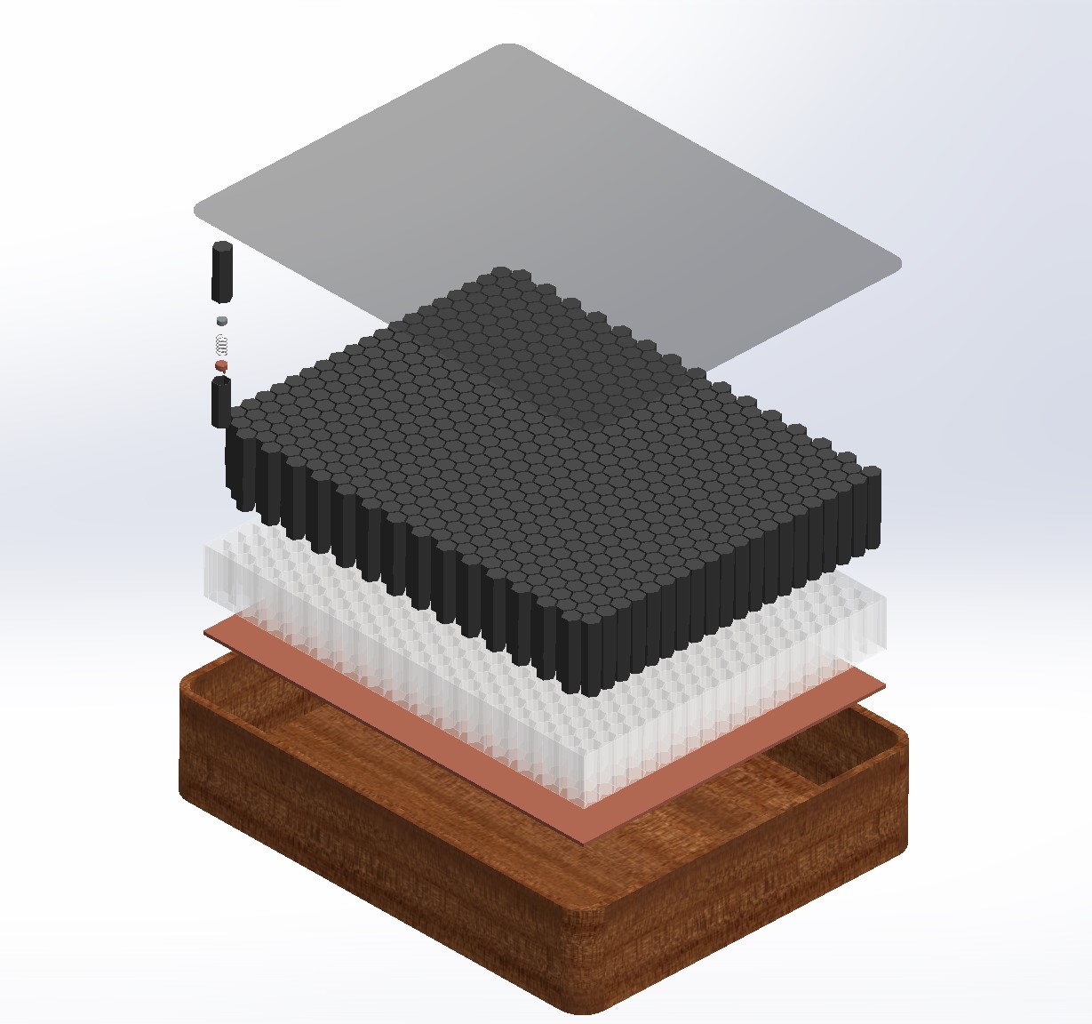
This is the heart of this weeks assignment. With the actuation concept identified, let's do a quick CAD of the device to give the concept a physical form. Below is the cutaway and exploded views for the actuator.
Now we can get started on bringing the CAD of the entire system into view. The pistons will likely need a form factor to keep them aligned and in place, the electronics should live below the postons, and to conceal the actuators and electronics, I think a wooden box to package the concept would be a nice touch. The fabric sheet will be on top of everything to give the appearance of a continuous fabric of space and time.Below is the CAD for the concept system and an exploded view to detail the components.
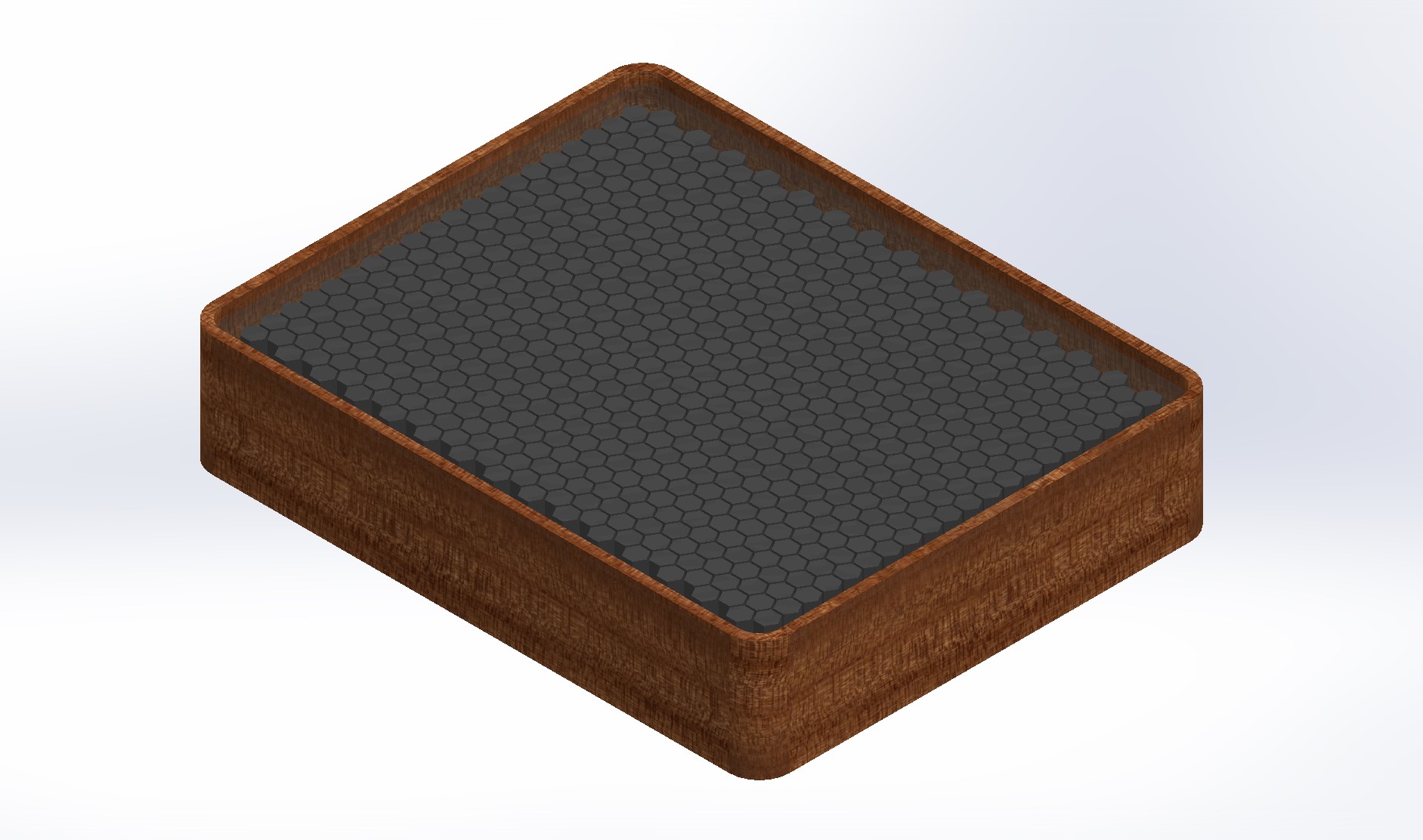
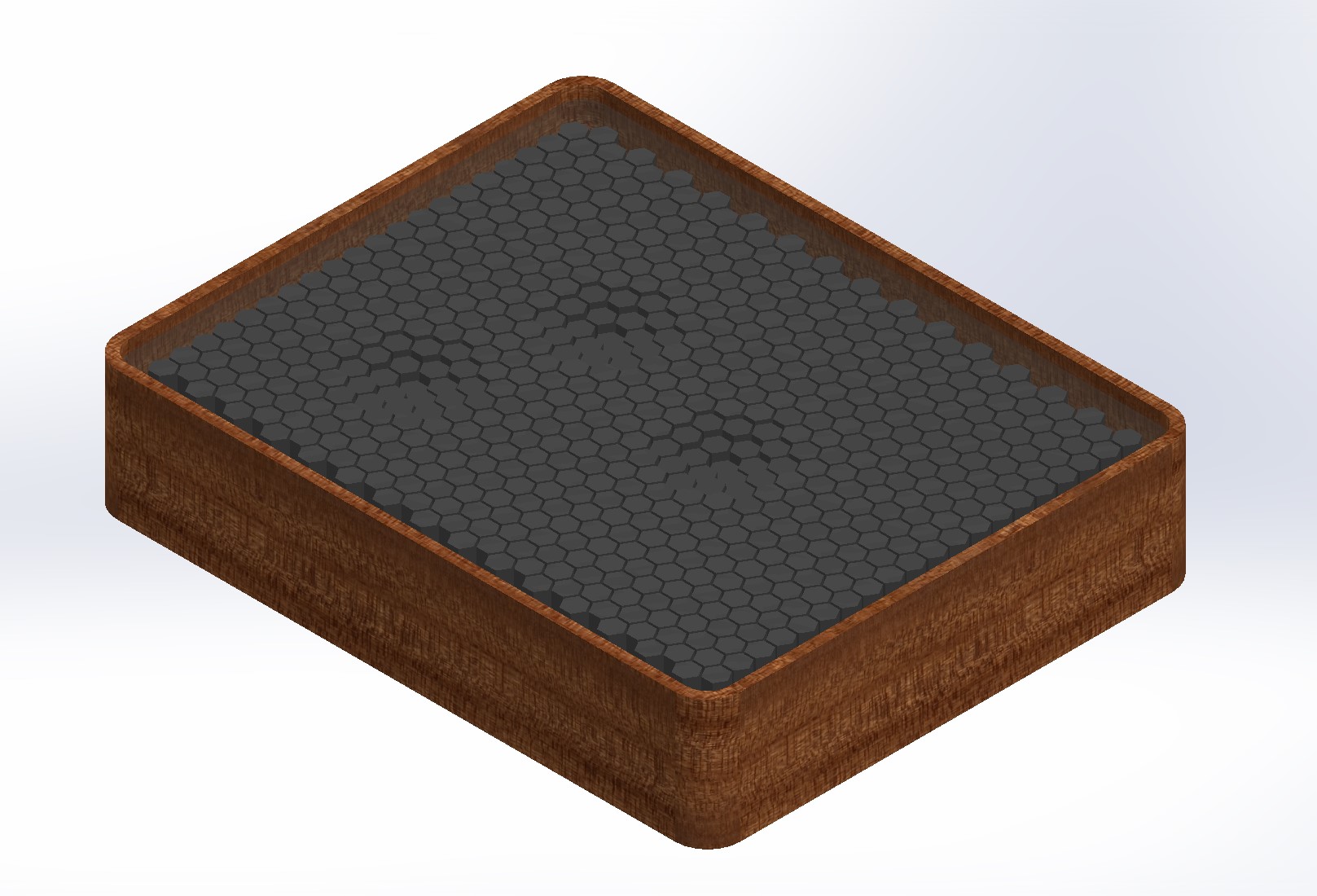
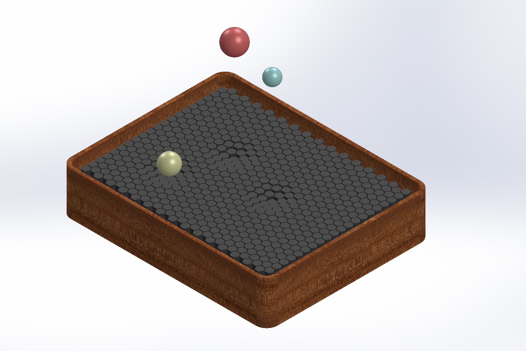
Now the concept can be illustrated more accurately. Another exploded view was generated but this time to show the depressed pistons in their actuated state to create the appearace of gravity wells. We can also add in some suns for fun too. At this point I like the look of the exposed hexagons, so I might forego the fabric. This can be an option I decide on later as it won't be too challenging to add it at the end.
System and Software Design
To achieve the desired motion, I plan to generate a heat map of the actuator grid that is mathematically determined based on the scaled Keplerian mechanics equations, user inputs, and the previous locations of the suns. Essentially, the position of the suns will be a signle, entirely depressed actuator that is then surrounded on all sides by 2/3 depressed actuators which are also surrounded by 1/3 depressed actuators. If the number of depressed actuators here isn't feasible because of power budget, magnetic interactions, etc, then the 1/3 depressed actuator ring is not strictly necessary but would look visually pleasing. The heat map data flow is shown below to better illustrate this concept.
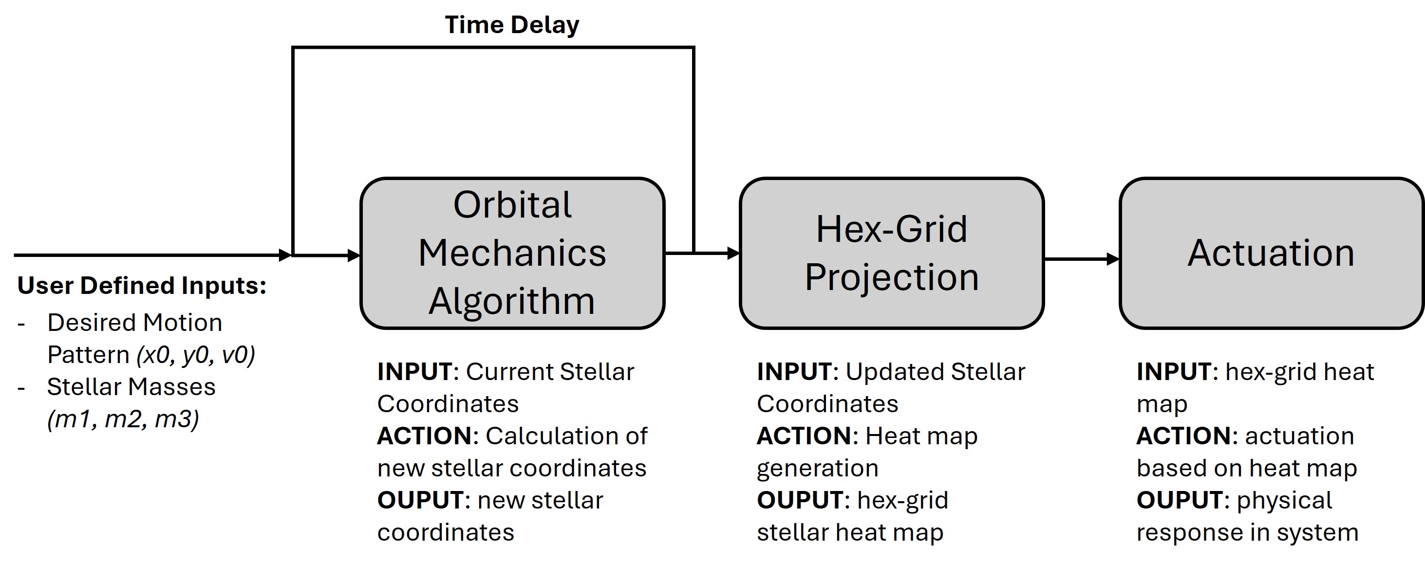
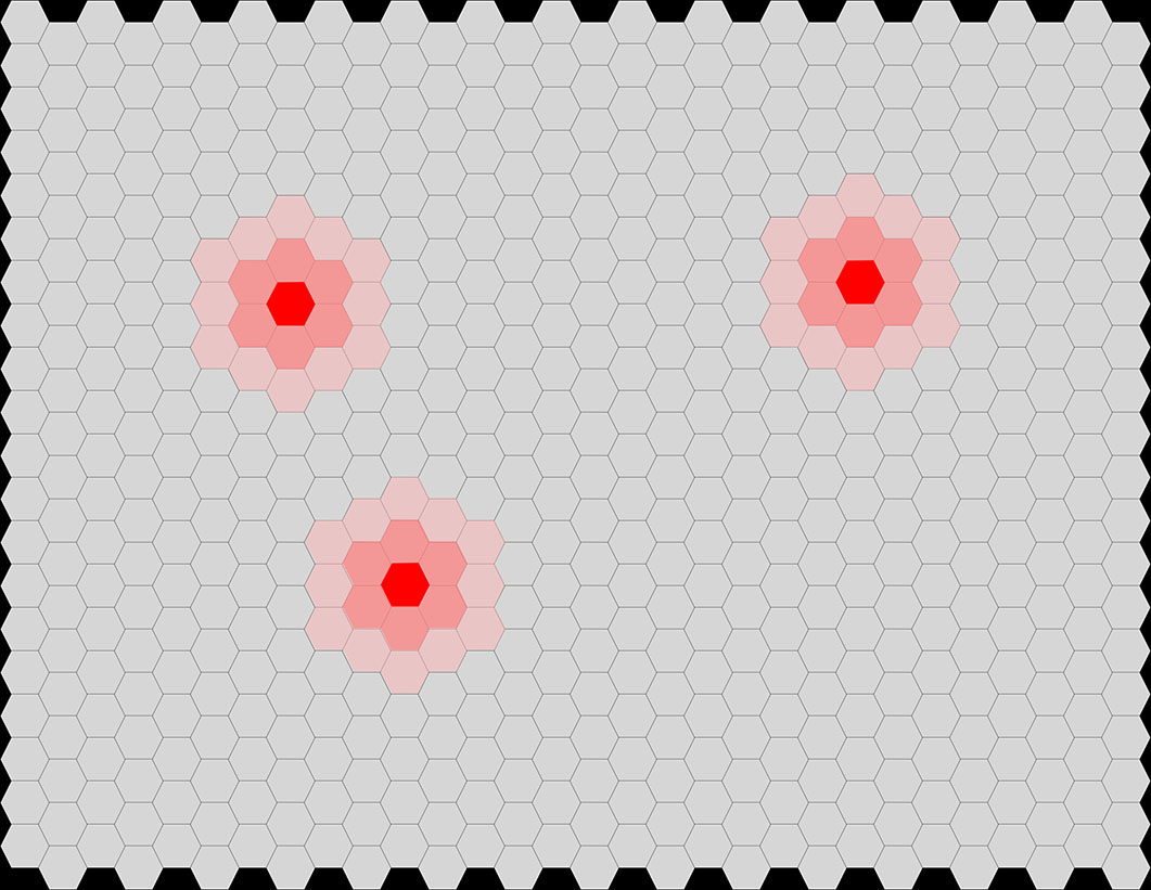
User inputs for the desired motion pattern (essentially the initial conditions) are required, and the possibility of setting the stellar masses is also being considered. These inital conditions are fed into a Keplerian mechanics algorithm that will then output a new set of conditions to be fed back into the algorithm as a loop. This data will also be used in the next flow process to generate the heat maps for actuator activation, and finally those heat maps will be actuated for the visual effect of the gravity wells populating the board. These wells will draw the suns with them and create the motion of the device. The heat maps will be mapped to the hexagonal structure, and while the stellar coordinates will be fed into the heat map generator, the algorithm will add the buffer layers around the suns for visual appeal. An illustration of the heat map is shown below
One thing to consider here is that to avoid any suns colliding with eachother, the heat map generator should be able to maintain a certain perimeter for each of the suns (to avoid having two of the fully actuated hexagons being either overlapping or right next to eachother). This threshold will probably be determined experimentally.
This concludes my week 0 assignment (although in truth I did this over several weeks as an initial project development, but it still meets the requirements since I modeled the idea in several ways both physically and abstractly!) so it is off to next week!