3D Scanning & Printing

This week the task is to make something using the 3D printers that would not be possible to make using subtractive manufacturing. Subtractive manufacturing refers to processes that use lathes, mills, and other machines where you start with a bulk piece of material and slowly carve away at it, rather than additive manufacturing where you sequentially add material to build an object layer by layer. The process is powerfull and enables an seemingly infinite possibility of complexity to be added to a design.
To start off the week of 3D printing and scanning, we needed training using the CBA (Center for Bits and Atoms) shop printers. The CBA shop has several Prusa Mk4 and Bambu X1 Carbon 3D printers. These printers are in the category of FDM (fused deposition modeling) printers, where filament is extruded and fused to the previous layer of extrusion. These printers have limitations, however. To characterize these limitations, test prints are often made to identify where the printer begins to fail when given edge-case tasks. Below is the test print for the Prusa Mk4 printer used in the lab.
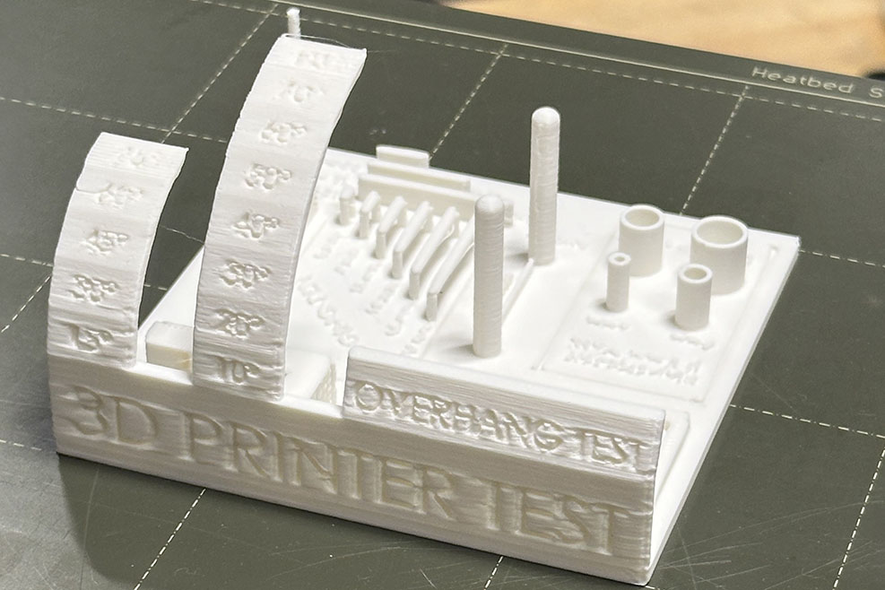
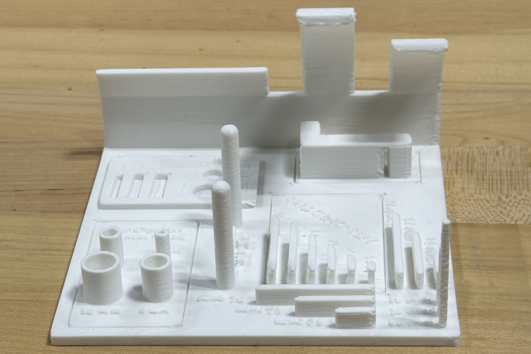
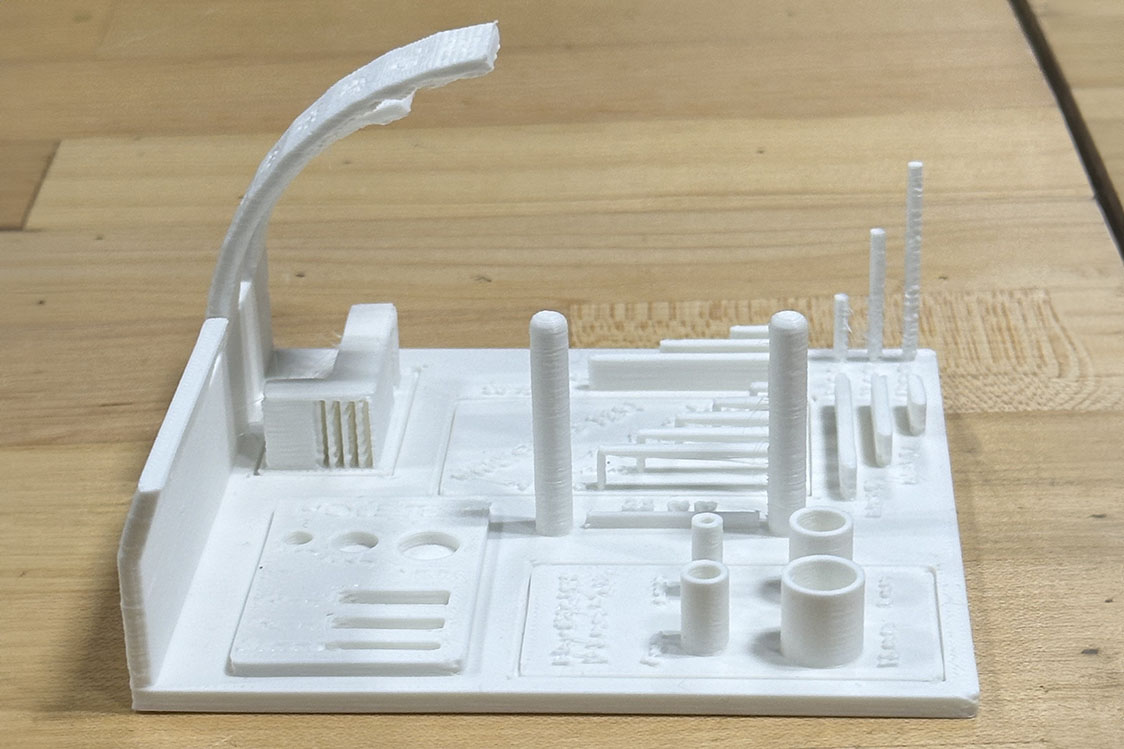
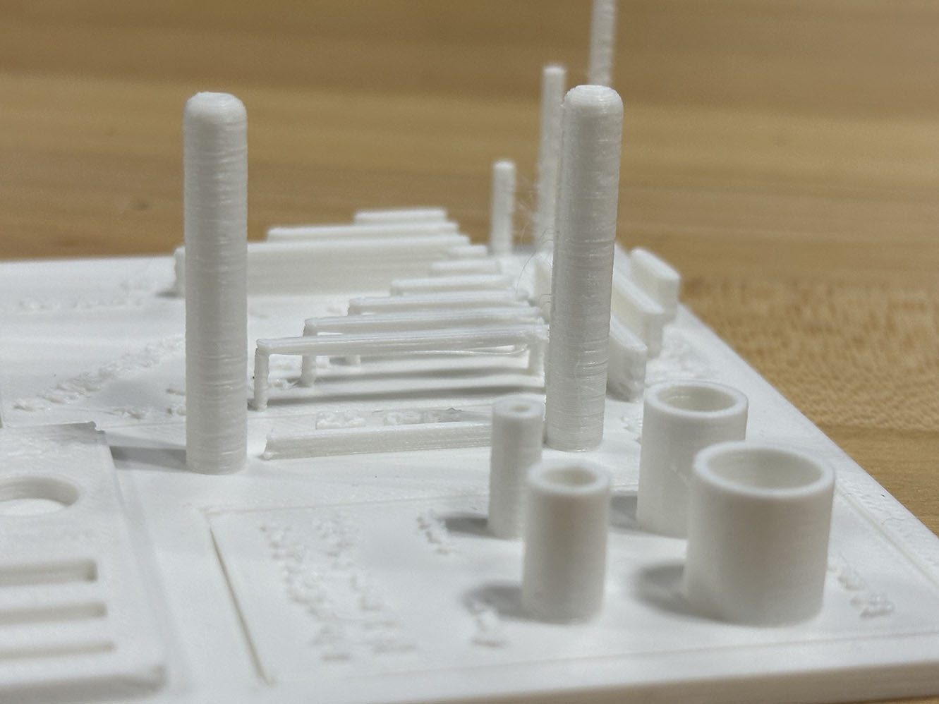
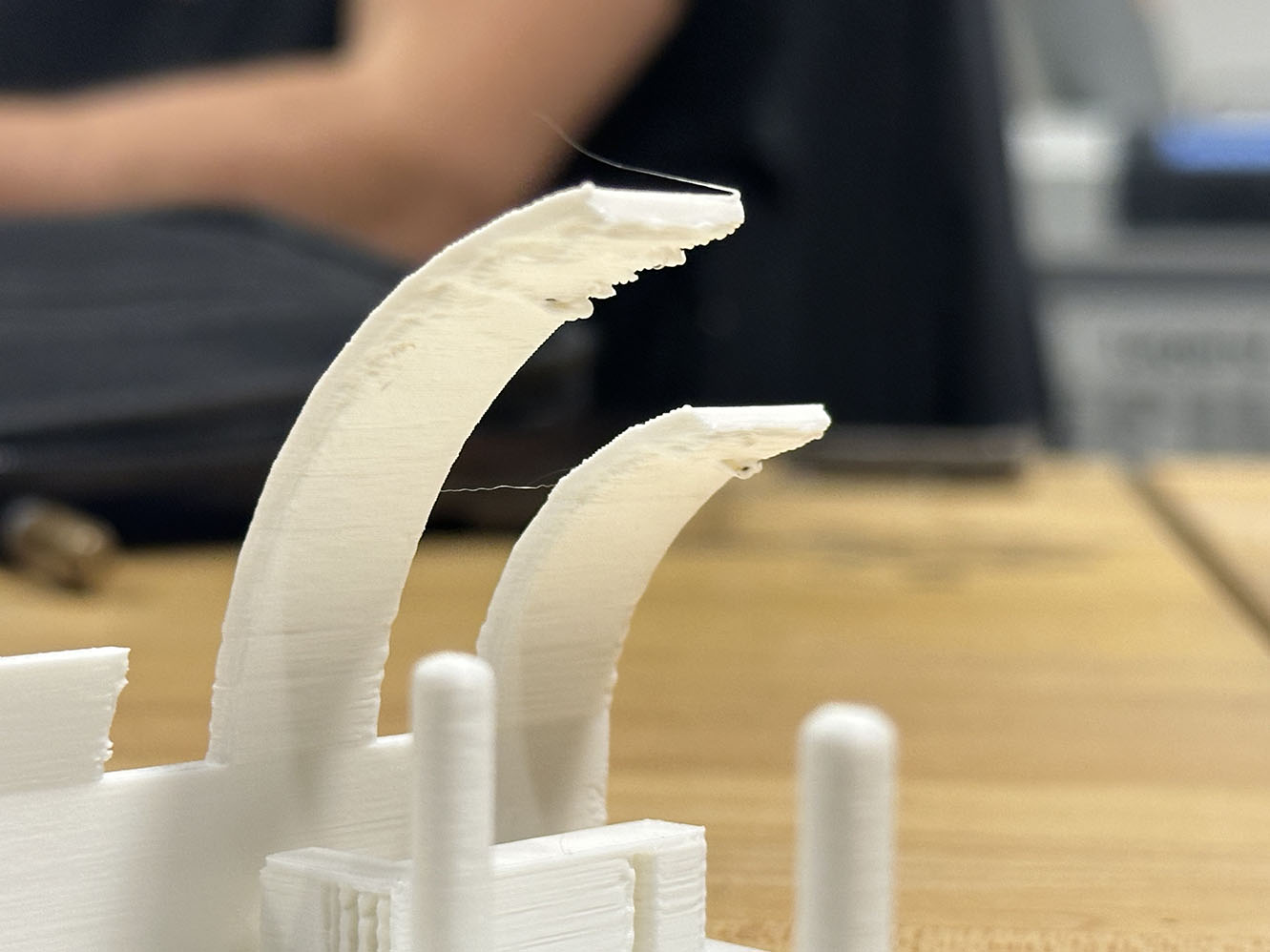
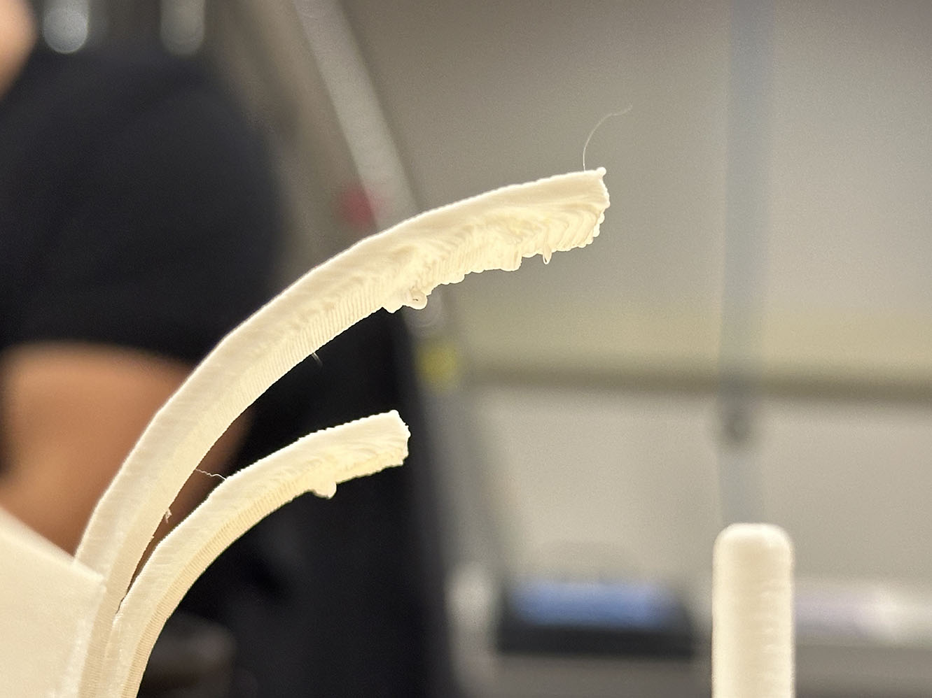
Notice that there are several sections. The most obvious is the overhang section where the printer is tasked with printing increasingly difficult angles of overhangs. Seen here the printer begins to have some spaghetti form under the overhang at the 60 degree mark. Additionally tests are run to see how thin of an extrusion the printer can make, how dimensionally accurate the prints are, how narrow of a gap the printer can tolerate, and if the printer can make a bridge-like structure. These printers run remarkably fast and are able to produce the more strenuous parts of the print test with surprising success.
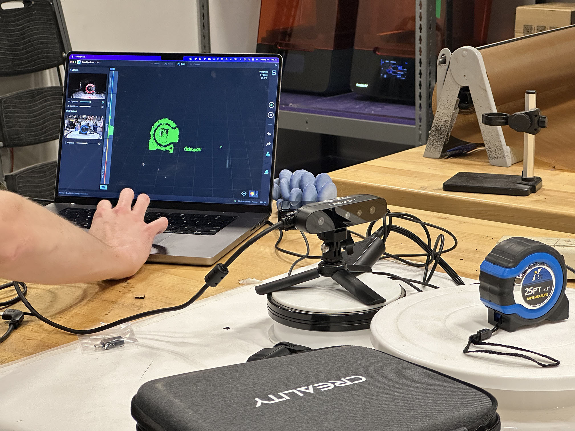
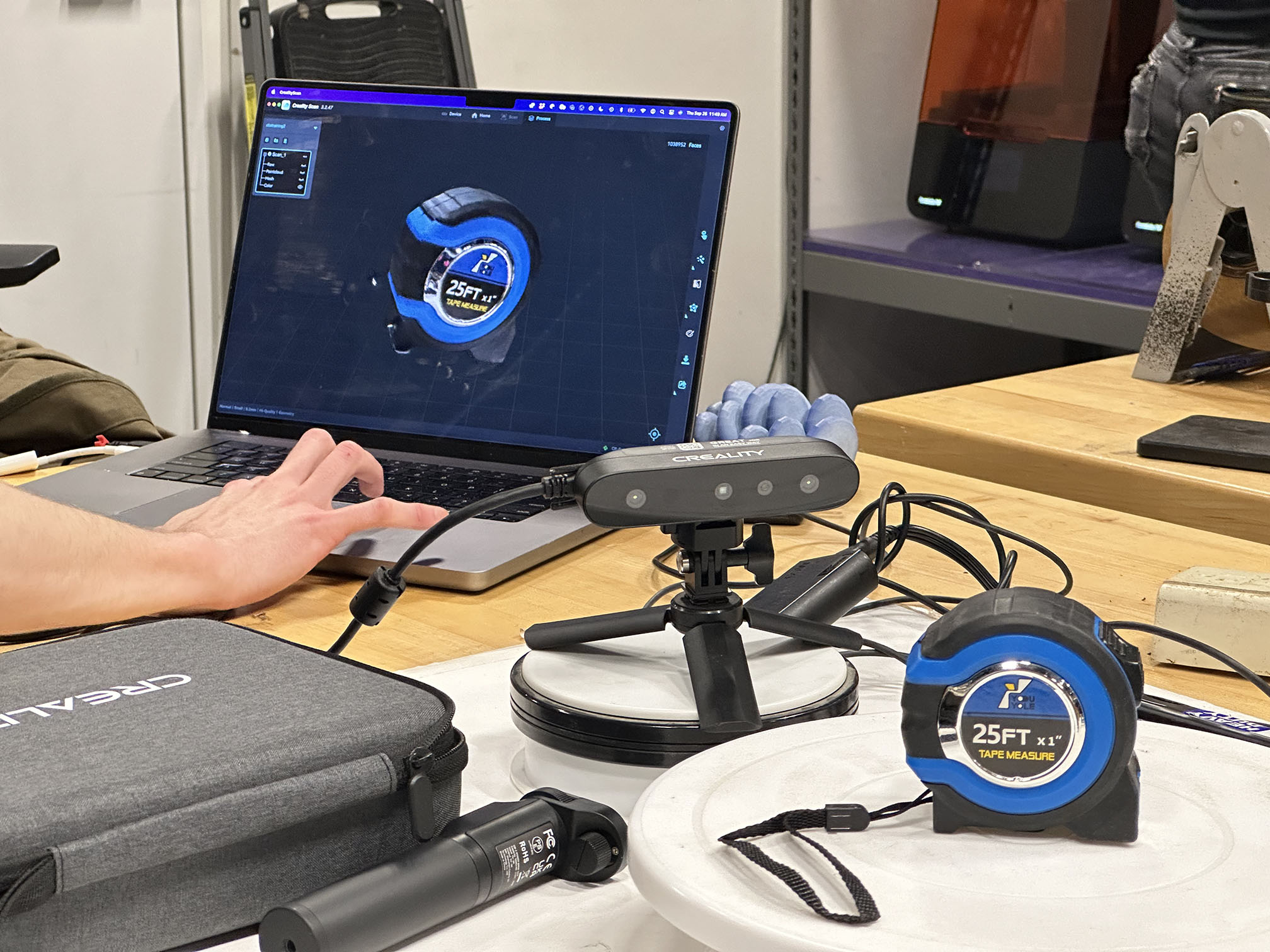
With the printer characterized, the group assignment is complete. The second part of the individual assignment focuses on 3D scanning, so let's knock that out while we're in the lab. Here, a Creality handheld 3D scanner is used to scan a tape measure. This model is a steroscopic scanner, meaning that two cameras rectify images into a depth of field measurement across a set mesh of measurements, much like how our eyes work. The object is plased on a rotating table and spun for the scanner. Many scanners have trouble recognizing reflective surfaces, but this one was able to pick up the metallic features of the tape measure pretty easily, seen below. For an inexpensive consumer device, it is rather powerful and accurate.
With the scanners and printers characterized, it's time to move to making something that would otherwise not be possible with subtractive manufacturing. I have a few ideas for this. The first is to print a small vacuum balloon with a compressive strength / weight optimized internal structure. While very interesting in my opinion, there are a few hurdles in printing this. First and foremeost is the challenge of evacuating the balloon. You could try to print in a vacuum chamber, but convective cooling is used when printing in FDM to ensure that the material is molten when printing but solid after being deposited, so much effort would need to go into the cooling process to ensure the quality of the print in an evacuated space. The other main challenge is that FDM printers are not gas tight - small gaps in between layers and the porosity of most materials makes printing gas seals nearly impossible here. A resin printer could be used but when printing an enclosed, hollow volume on a resin printer you run the risk of trapping excess resin inside the print, adding weight. For the purposes of this assignment, a vacuum balloon might be out of scope (although this would make a super interesting topic in the future, perhaps with metal printing or something of the sort!).
 The other possible project I am considering is creating a paper airplane. While you could subtractively manufacture the outer shell of a paper airplane geometry, you would lose the internal features that make the airplane interesting. Jack Forman developed an interesting method of 3D printing textiles by starving ordinary FDM printers, seen to the left (learn more here). By combining both the fabric printing technique and the internal structure of a paper airplane, I think it would be interesting to see if I could print an already folded "paper" airplane and fly it in class ("oH yOu WiLL nEveR bE aLloWeD tO tHrOw AiRpLaNeS iN a cLaSs iN cOlLeGe" - you know who you are). I do anticipate running into some issues with the porosity of the surface material again, but let's see if we can get this idea off the ground regardless.
Ok so to kick things off we need a CAD model of a paper airplane. This is, as I am discovering, a far taller order than I initially considered. In the interest of efficiency, I took to the internet to search for an existing CAD model. No such luck. Oh well, let's see if I can make one using one of those handy online origami simulators. 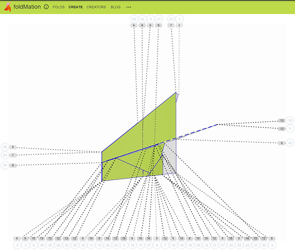 The results of that endeavor can be seen here off to the right. It's not ~bad~ per se but it does leave much to be desired. An additional issue is that I can't actually download this model. Ok so what's next? Perhaps the cutting-edge of modern technology can help.
AI has grown exponentially in the last few years, so I figured I could give it a try here too! Whats the worst that can happen? Well, as it turns out, AI is not so great at making paper airplanes. Womp womp. Below you can see a very ~creative~ interpretation of a paper airplane generated by text-to-cad.
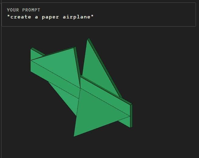 I don't have a very high confidence in this design flying well. It was worth a shot, but this is more or less what I anticipated. Ideally, I would be able to use the benchtop CT scanner that the CBA shop just acquired; however, that might a tough sell for this project. I want to see the internal structure of the plane as much as the outer form, so an X-ray scan would be great, and it would allow me to do a 1:1 comparison between the folded model and a printed one. The problem of visualizing the internal structures is why I can't optically scan the surface of a real paper airplane and print the scan. Both the outer and inner structure are equally important in making a paper airplane fly the way it does. I'll see what strings I can pull to get my hands on the CT scanner (likely this will be an email asking nicely), but in the meantime, I think I will need to creatively model one in Solidworks myself.
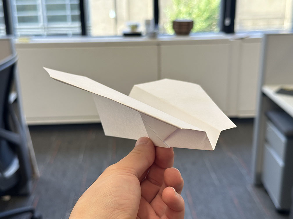
For a design in Solidworks, I want to use a reference model. From decades of experience in the field of paper-based aeronautics, I have settled on what I believe to be the best paper airplane design. It is a balanced design and offers a lot of room to adjust the flaps to get loops, rolls, dives, etc. This design can be seen below, and will be the basis for my CAD model.
Unsurprisingly, most modern constraint based CAD solvers are not set up to optimize the workflow of digitally folding a paper plane. Every online resource I could find told me to make use of the Solidworks sheet metal bending tool. This tool is incredibly powerful for making bent parts from sheet metal, but begins to fail when trying to do complex folding patterns. This is also not a big surprise. Most sane people would not be trying to fold an oragami crane from 310 stainless sheet stock; however, for the niche crowd of not-so-sane grad students trying to reinvent the wheel for a class, I do need that feature.
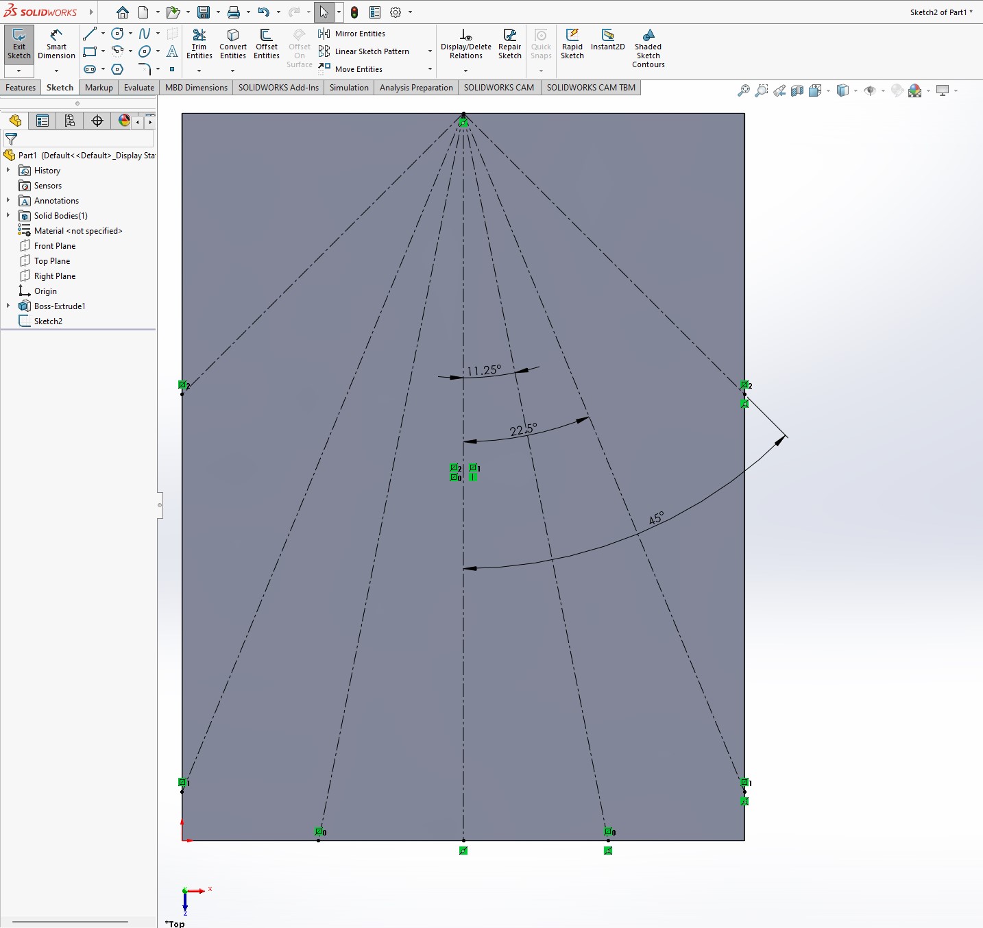
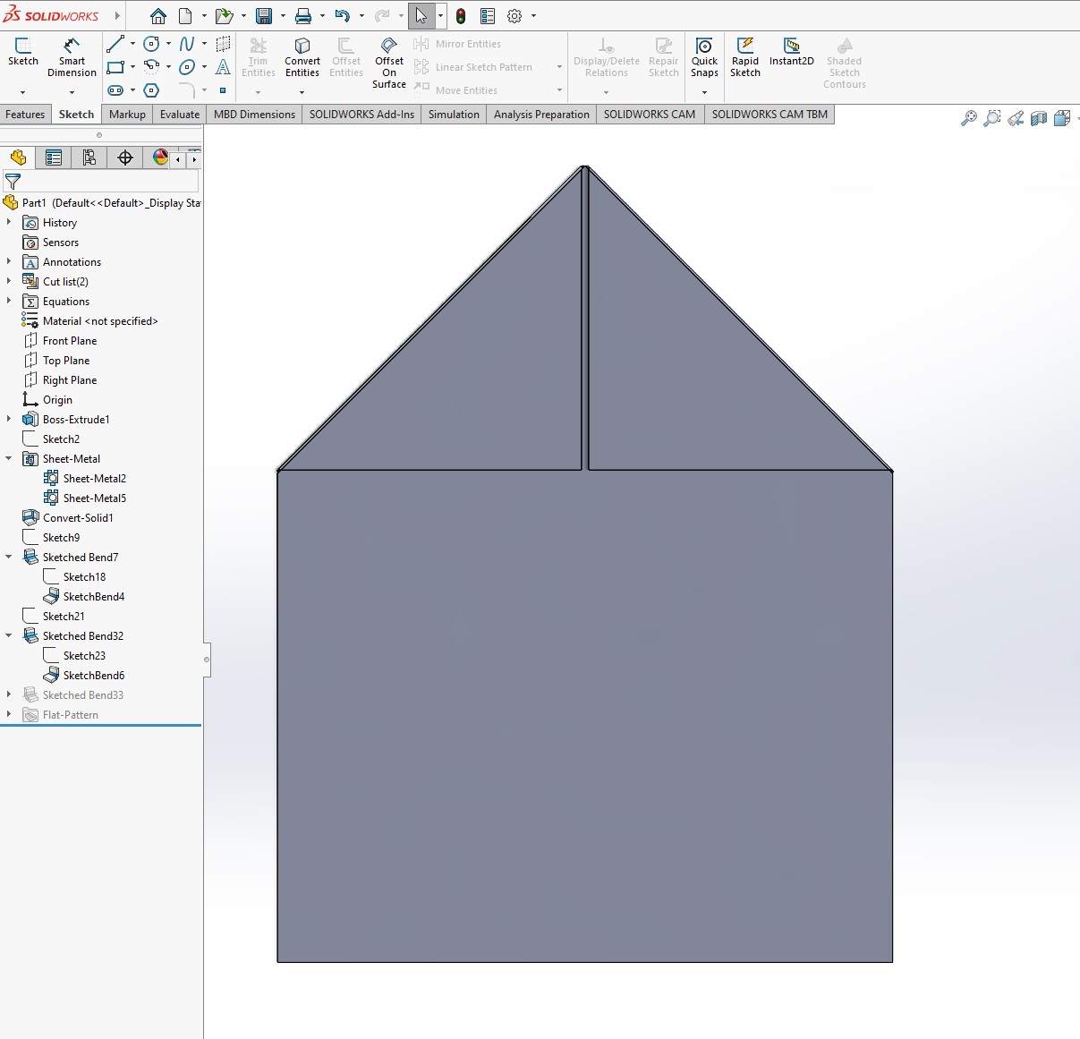
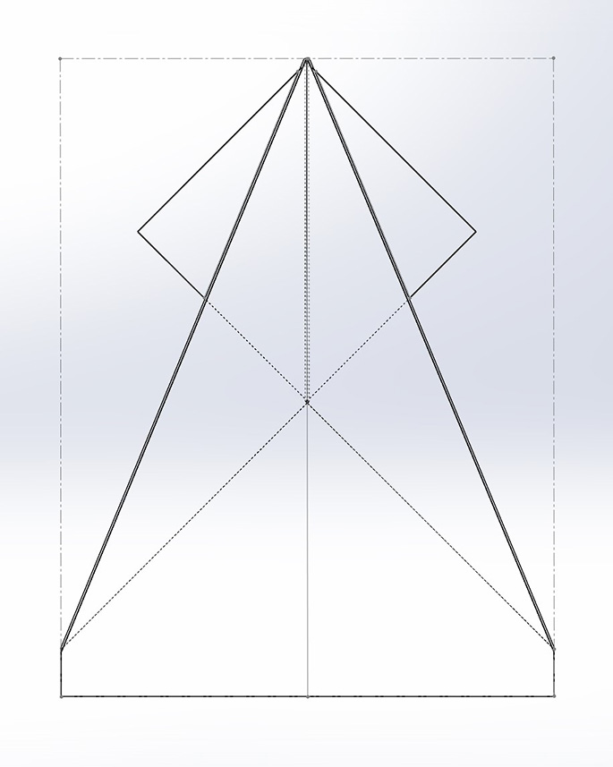
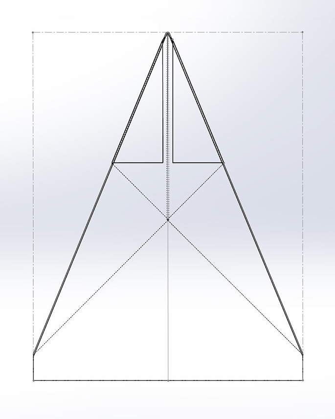
To dive a little deeper as to why the sheet metal bending tool fails, the issue is when a bend is placed over a non-uniform set of surfaces. This is illustrated in the progressioon of images below. The first in the series is all of the fold lines for a classic dart paper plane. This was largely made as a tool for me to understand how the sheet metal bending feature worked. I made the first to bends, as shown in the second image with no problem. These were single bends that did not overlap and occured on a single face of a surface. The next figure shows the subsequent fold, and the following lines for the next fold. This is where the tool failed. The diagonal lines to begin the wing shape cross over between two different layers of the paper. In order to solve this fold, Solidworks needs to vary the bend radius for the inner and outer sheet of the bend. It has no way of doing that currently, so folds can only ever cross a single layer of the paper. Solidworks actually has a tutorial on how to make a paper plane using this tool, and their design is cosmetically a plane; however, when I folded it, it did not fly. This wasn't a big surprise to me since there was no layering to create an airfoil to generate lift. The tool constrains a paper plane design to only ever have one fold overlap. No existing paper plane (that I am aware of, at least) abides by this constraint and is able to fly. This leaves me with the task of designing a new paper airplane to meet these constraints - lovely.
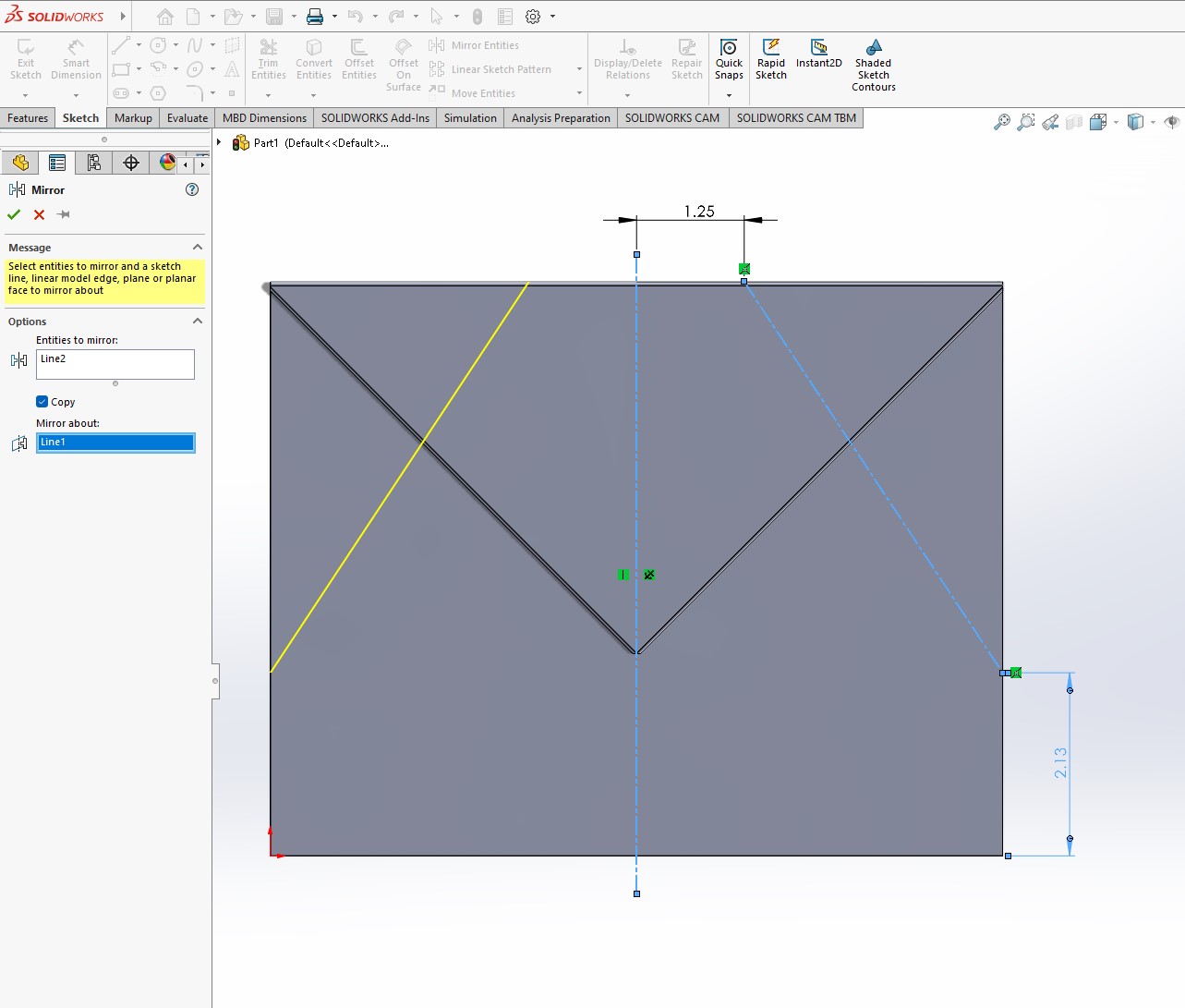
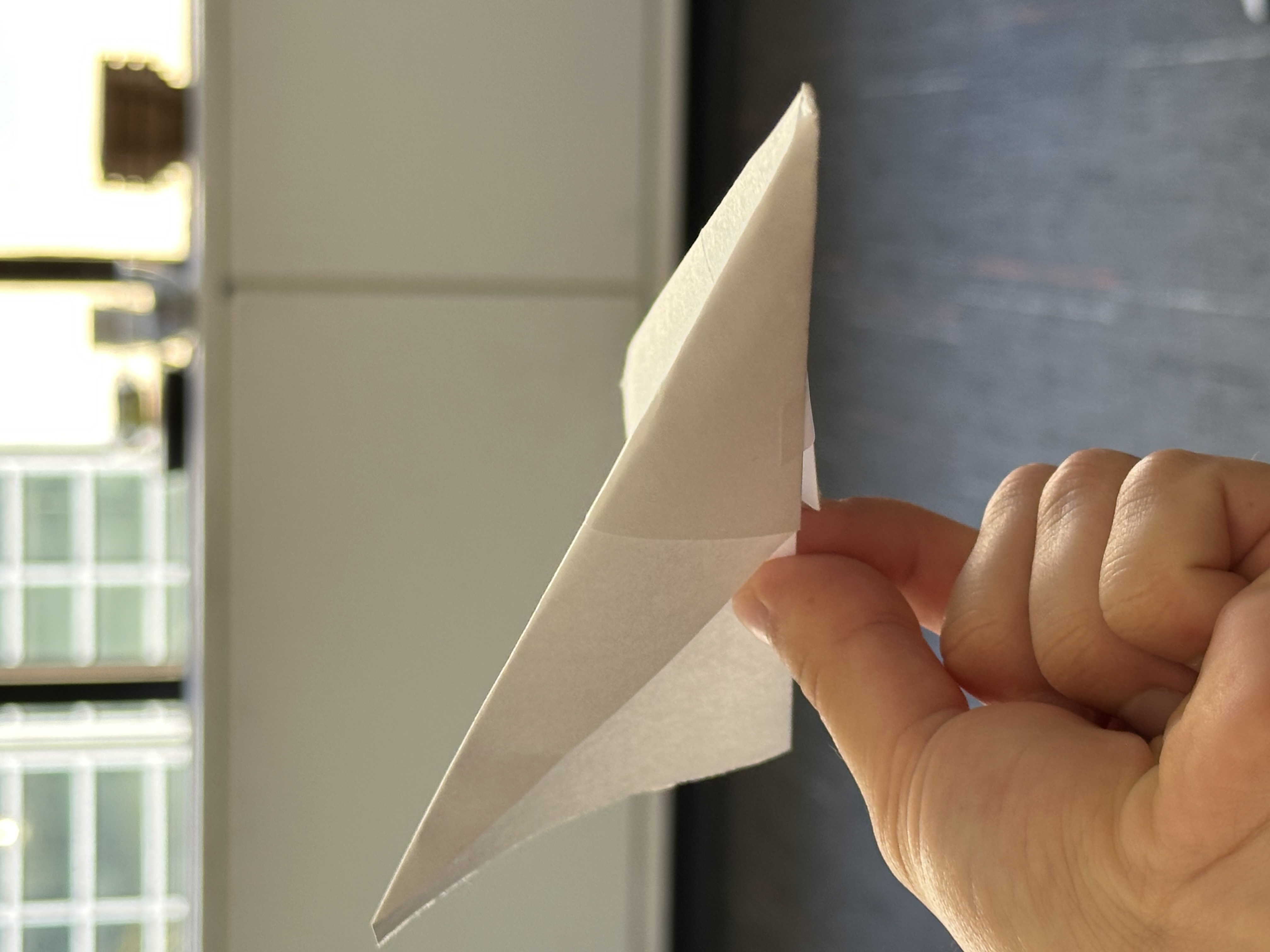
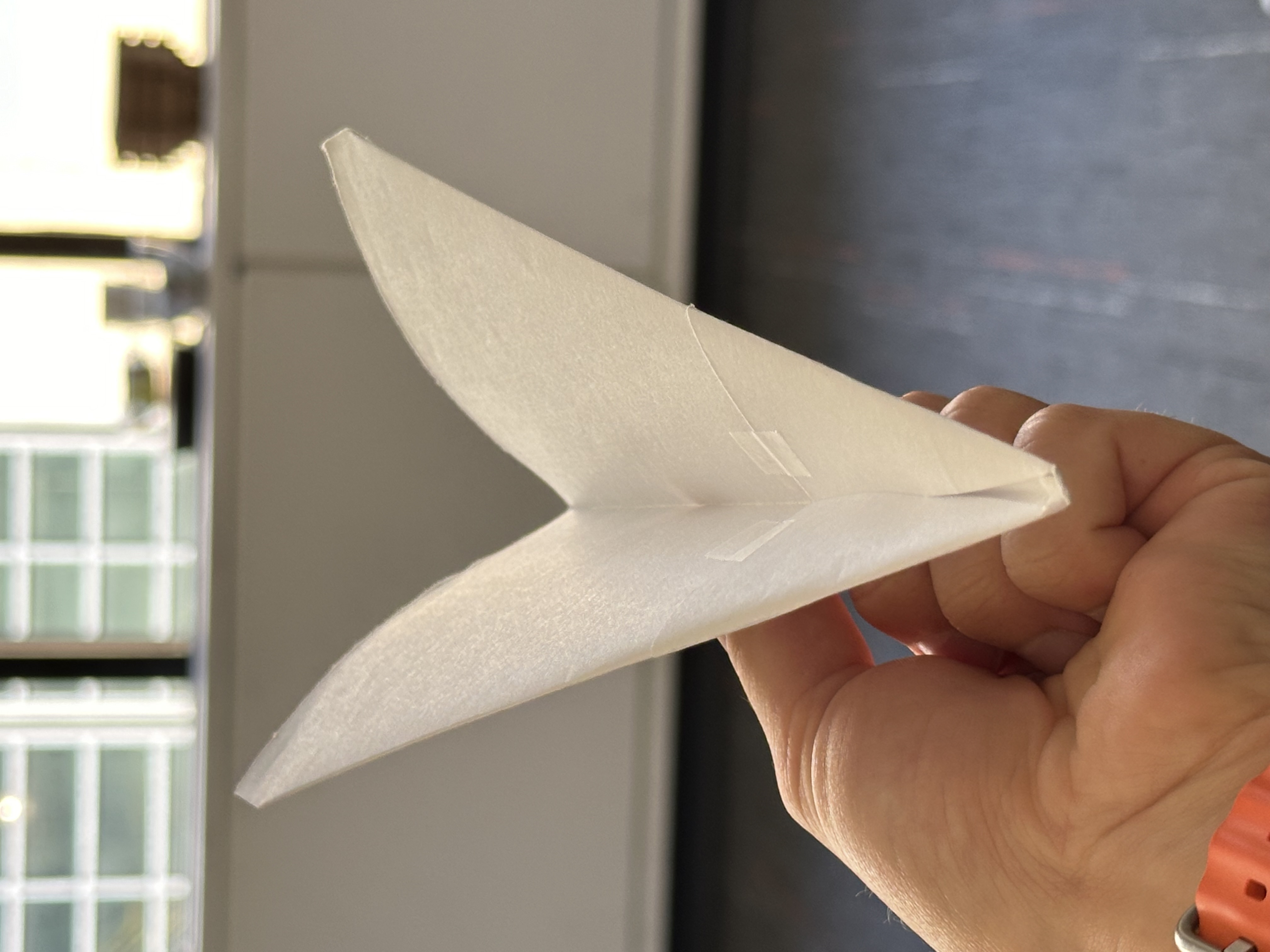
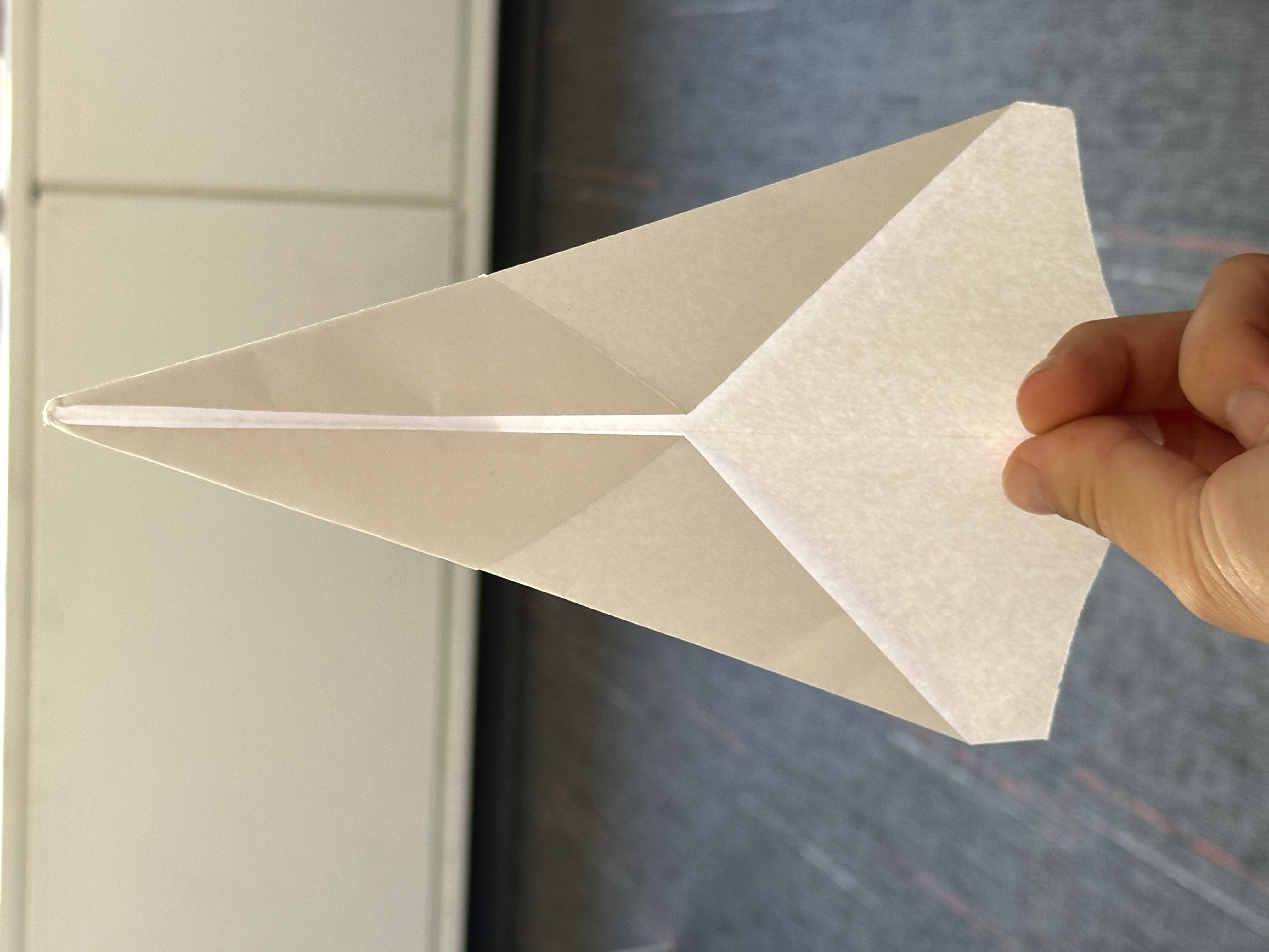
Interestingly, paper planes fly using similar aerodynamics as "flying wing" planes, but make use of natural passive stability (i.e. the plane tends to fly upright without making use of an active control system). While most designs increase stability through a folded "fuselage" that additionally provides vertical stability, they don't really need this to fly. Most all of the final wing folds in paper airplane geometries violate the constraints of the bend tool since good wing designs feature multiple cascading layers folded over one another to produce a small airfoil. This slight bump in stability is nice, but is not strictly necessary. With this in mind, I decided to modify the simple "dart" plane design by making the last fold inverse from the typical pattern and having the plane be a "flying-V" shape. When adding tape to keep surfaces pinned together, this design flies quite well. Below is the modified dart, with all constraints for the Solidworks tool met.
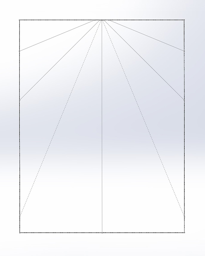
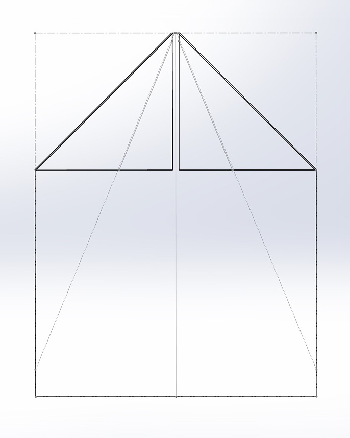
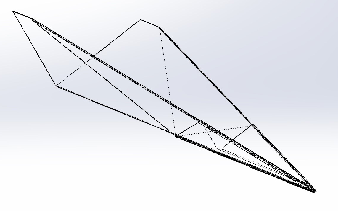
Since this design flies and abides by the Solidworks tool constraints, it's time to (finally) CAD a paper airplane. Starting with the first figure, all fold lines are shown (I adjusted the view to be a stencil to make this easier). Like with the previous design, the first folds are the top corners. Next up are the reverse folds for the dart. This creates a sort of "forewing" for the plane, but those flaps are folded again back to the center. This completes the folds for the modified dart, and the plane is now folded into the "V-shape" shown in the final image.
And for your viewing pleasure, here is a video of the CAD model ~spinning~.
Now that we have a CAD model of a paper airplane, complete with modeled internal structures, it's time to print! The idea here is to print the plane using Jack's "defextiles" style of printing, so that will be the first step in our printing journey. The settings for defextile printing are well documented. Essentially you starve the printer of filament and have it move slowly across a single vertical sheet. This combination causes the printer to "burp" filament out in a fabric like pattern. Easy, right?
I started by printing a simple sheet of defextile fabric, this geometry taking the form of a cylinder. I had Jack help on the settings and tuning of the print, but the mk4 printer seemed to have some differences in it's print method that caused the defextile print to fail.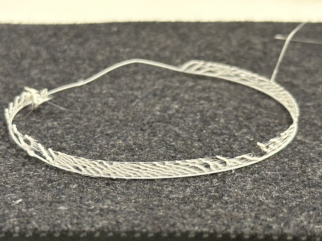 I used an extrusion multiplier of 0.28 and a speed of 1500mm/min with a Z-offset of -0.1mm. Printing with these parameters using PLA, in addition to defining the part as a single wall vase, should produce the fabric like pattern I was hoping for; however, this print failed. What is interesting is that the front half of the print was rather successful, but the back half was very much not. This trial can be seen to the right. I noticed while observing the print that the areas of failure did not have the string like interconnects that create the fabric "weave." This seems like an artifact of inconsistent filament extrusion, but after a thorough tuning of the mk4 printer I was using, the same result occurred.
In an effort to keep the project moving, I began printing the paper plane design with the defextile pattern. The sliced part can be seen to the left, using PrusaSlicer. The entire print time was estimated to be about 4.5hrs. Since the part was a single thin wall of filament, I added a skirt to promote bed adhesion. The speed and Z-offset remained the same, but I adjusted the extrusion multiplier to be 0.3 and then 0.5 with both prints exhibiting a similar failure mode as before. 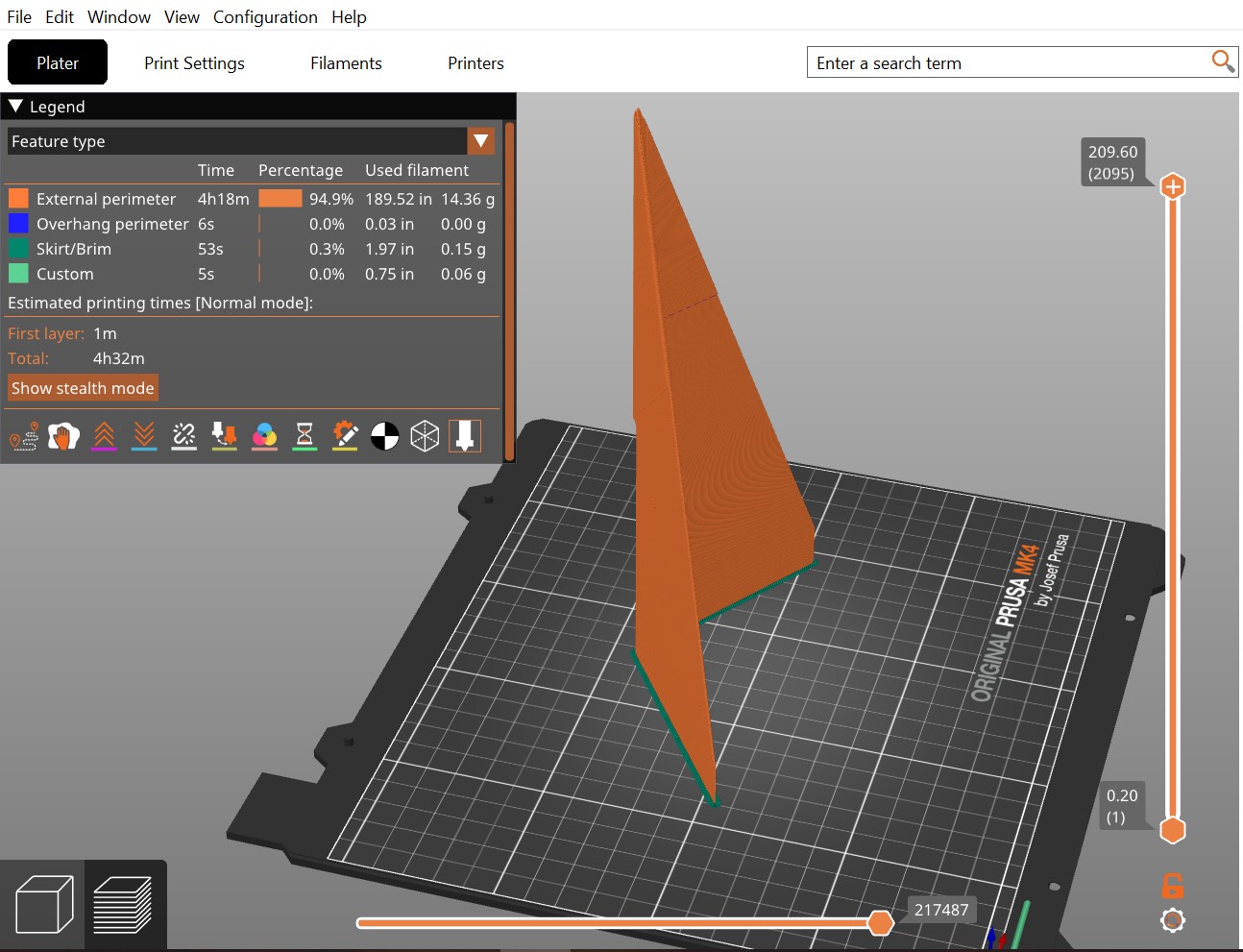 I then increased the multiplier 0.75 and hit what I thought to be the edge-case of my print. Seen to the right, the paper plane geometry is printing with 0.75 and is ~almost~ successfully holding together. Another interesting anisotropy, the right side of the print is closer to the pattern I want while the left is much more sparse and not holding together well. There also seems to be much more junk filament on the right edge of the print as well. Again, I'm not entirely sure why this is, but my spidey-sense is telling me there is an inconsistency with how much mass of filament the printer extrudes during different parts of the print.
 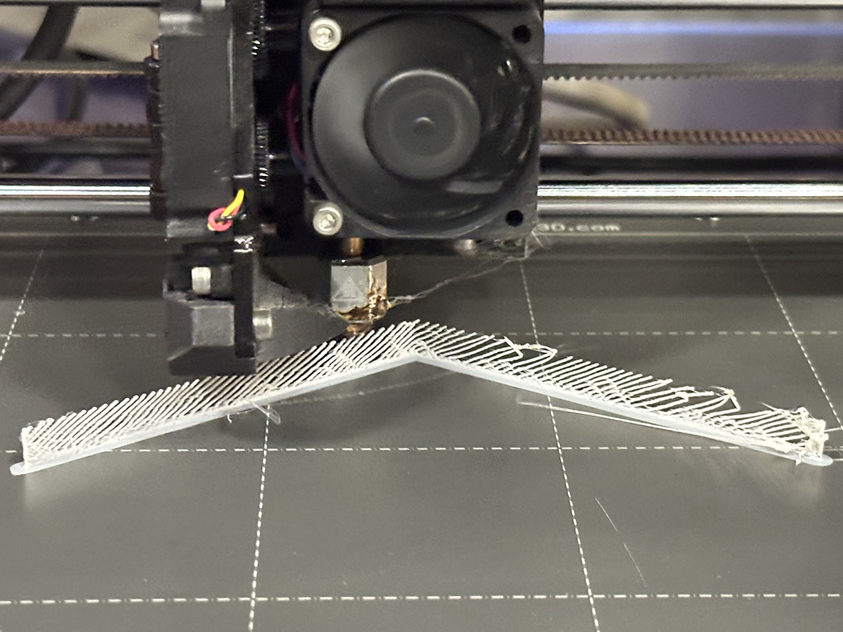 This would make an interesting point of comparison by printing the same binary file on mulitple mk4 printers and then switching to a mk3 and even a different brand of printer. I suspect that the print characteristics would change somewhat, but that is sadly beyond the scope of my project for the week.
At this point I decided to eliminate the variable of defextile printing and just test my geometry with an extrusion multiplier of 1.0, speed of 2100 mm/min, and Z-offset of 0.0mm. While I wanted to continue with defextile printing, I needed to at least have my geometry validated to ensure that the common error in my failures was not an unrealistic print. With the solid fill and single-layer print, my first successful "paper" airplane print can be seen below!
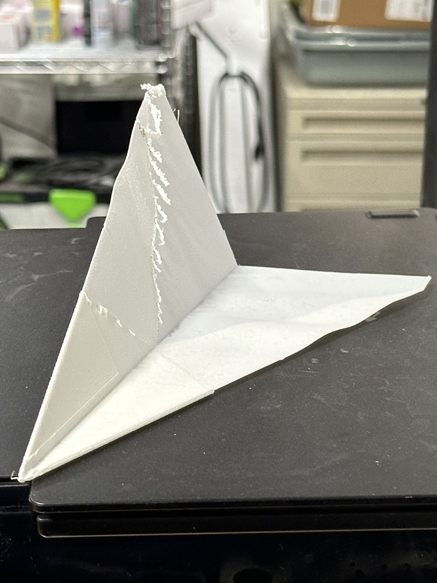
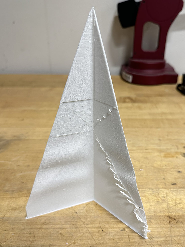
This is great, the folding geometry is clearly captured during the print. Moreover, the single filament layer seems to have been well aligned during the print. A little bit of warping can be seen, although this is not surprising. What is surprising and interesting is the excess filament build-up that can be seen on the plane's right wing. Only the right side has this build-up, with the left being clean and crisp. This is another subject that would be interesting to investigate further, but is beyond the scope of the week. The plane feels light for a 3D print, but heavy for a paper plane. It is also very brittle. I gently tossed the design into some soft grass and it did fly a bit! With that I consider the week a success, but we are still far from done.
I want to try and incorporate the defextiles print into this geometry now that I know the print works. The solid fill was certainly pushing the capabilities of the Prusa, and adding the complex pattern might throw it over the edge, but why not try. I noted on the solid print that a few gaps occured in the single sheet wall, what I would consider to be about 95% filled in. 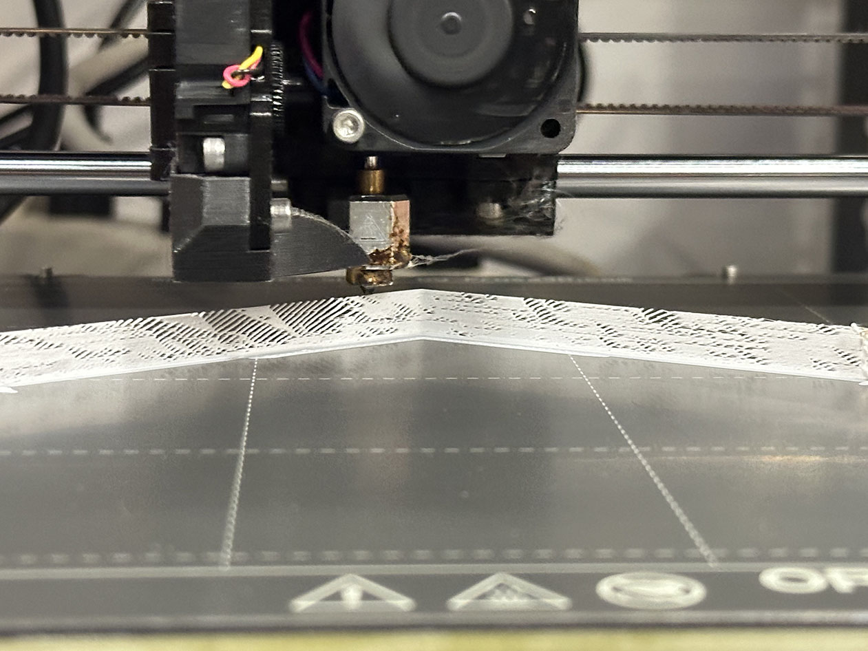 From that, I decided to work backwards and print starting with the same speeds and offset as the previous defextiles prints, but with an extrusion multiplier of 0.9. According to Jack's work, this is far too high of a multiplier to use to get the fabric-like consistency, but so was 0.75 and that failed so this print task has basically become a balls-to-the-wall no man's land of wild west printing. The initial print layer can be seen to the left, and it overall looks pretty good, but the anisotropy of sparseness is clearly seen on the left vs right sides yet again. Out of curiosity, I decided to leave it and see what would become of the print - "to hell with it" as my grandma would say.
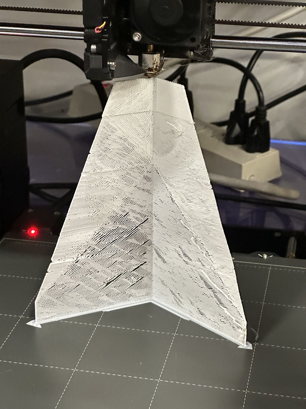 Turns out my grandma's mentality was a good one to adopt for this print, since I checked back in after a few hours and it largely looked ok! I noticed that with every sweep of the printer, the thin sheet like wings bowed and buckled slightly, but always returned to a normal resting position. This made me nervous but I mean, hey, it made it this far right? Why not give it a chance to finish out. You can also see in the 80% completed print that I added a bit more beef to the skirt. This was suggested by the slicer software after it determined that a few supports would likely improve print outcome. The sparseness is seen again here, and the folded structure is more clearly seen as well. Personally, I'm very excited for this print to finish up. It looks like it will be very delicate but cool nonetheless.
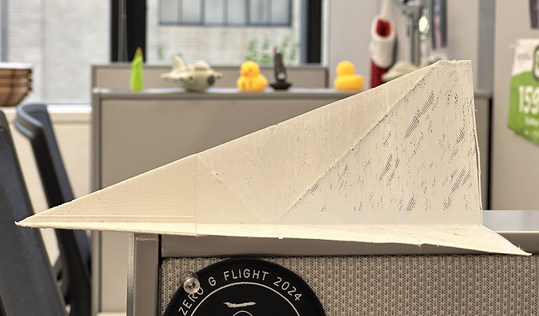
The print finished strong! Below are figures of the final print! It was considerably lighter in weight than the "solid" one, even with the extrusion multiplier set to 0.9 during the print. Honestly this came out much better than I had anticipated, and the combination of defextiles printing with the folded paper plane geomoetry looks very cool. It is incredibly fragile, however, so I have yet to throw it. I suspect that Neil will be keen to throw it in class, and I will be interested to see if it works then. Likely it will shatter into a thousand tiny pieces when it hits the ground. Ain't that just the way. I'll note that the brim of this print was VERY challenging to remove. The sparse layers wanted to unwind when I first attempted to gently pull the brim, so I used a razor to gently cut away at it.
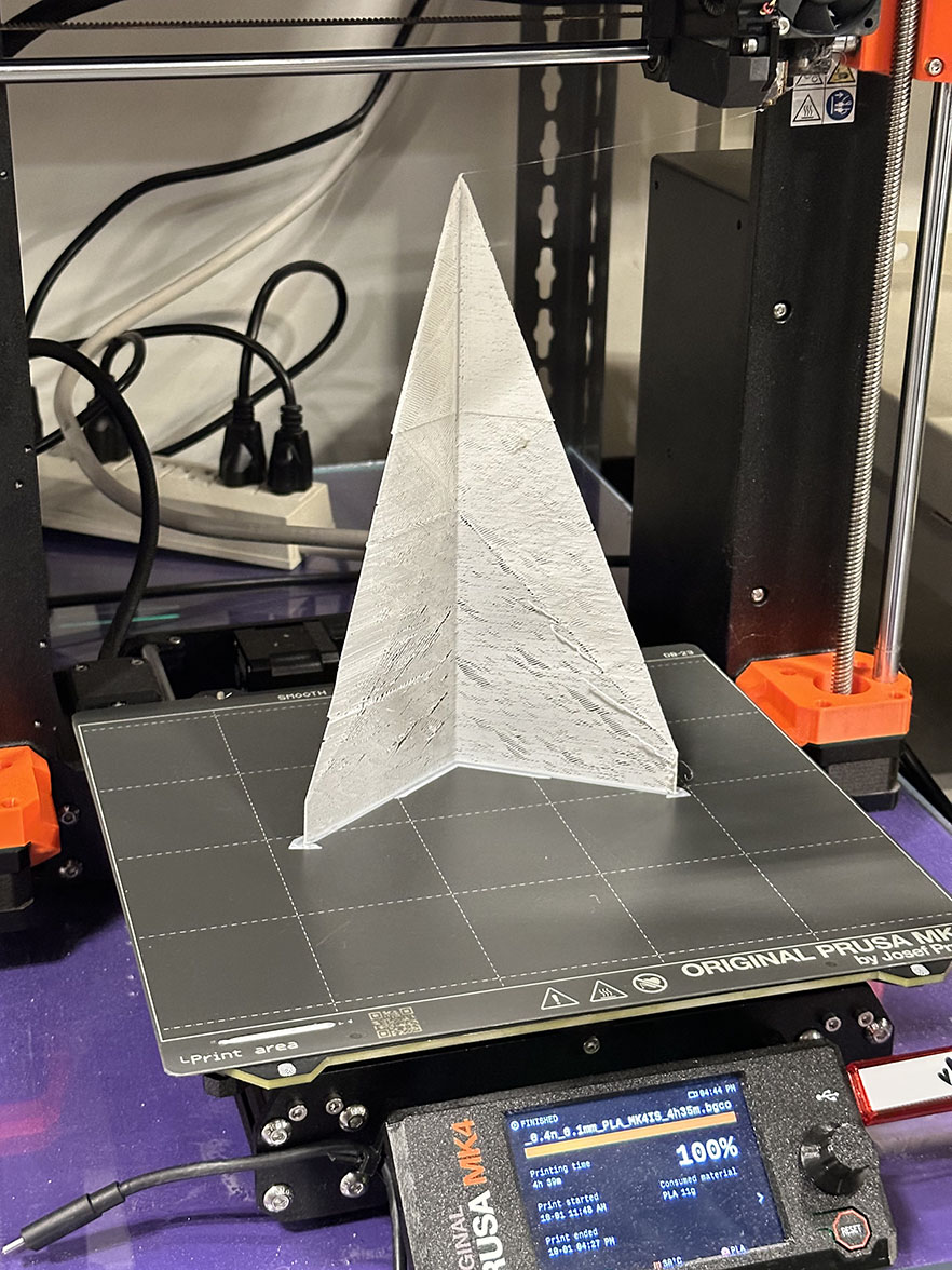
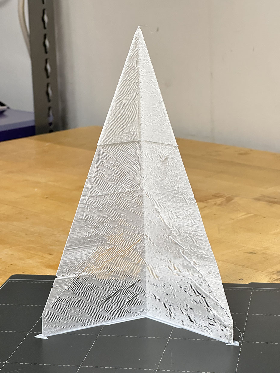
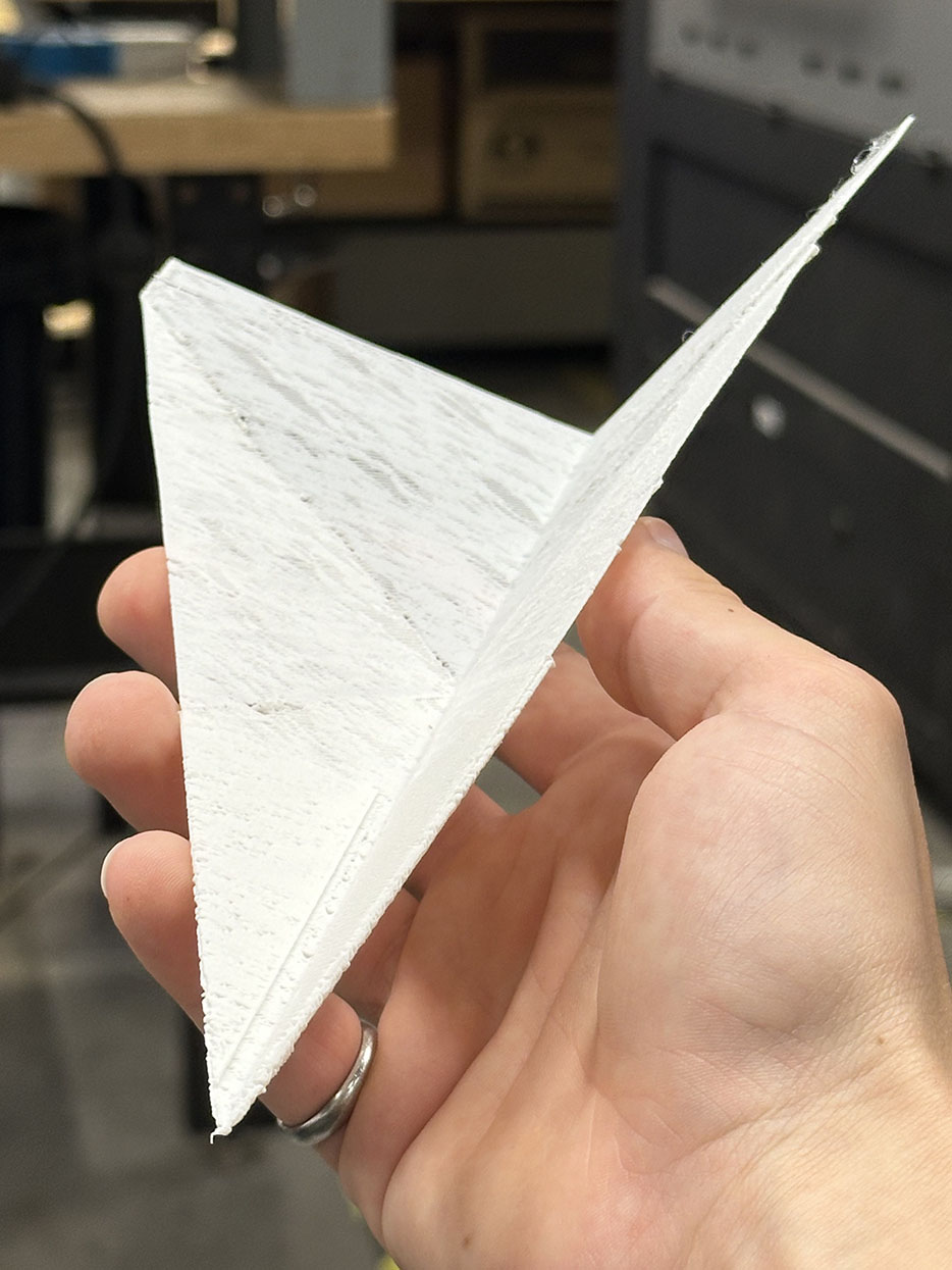
So there we have it. A flight-capable, 3D printed paper airplne that has intact internal structures printed with the defextiles technique. This week is a complete success. I have a fair amount of CAD and 3D printing experience already, but this was certainly a challenge and made me really think creatively to acheive my goals. Absolutely thilling week. 10/10. The Solidworks file and STL files for the paper plane geometry can be found below if you want to mess around and print your own! Enjoy another fun picture of the plane below, and we are off to next week!
- Download SolidWorks File
- Download High Wing Angle STL File
- Download Low Wing Angle File (this is the one I used here)
