Laser Cutting
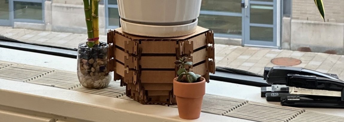
This weeks assignment is to create a parametric construction kit out of cardboard. The key here is to create a single unit that can be organized with like or slightly differing components to create a multitude of assemblies – akin to legos.
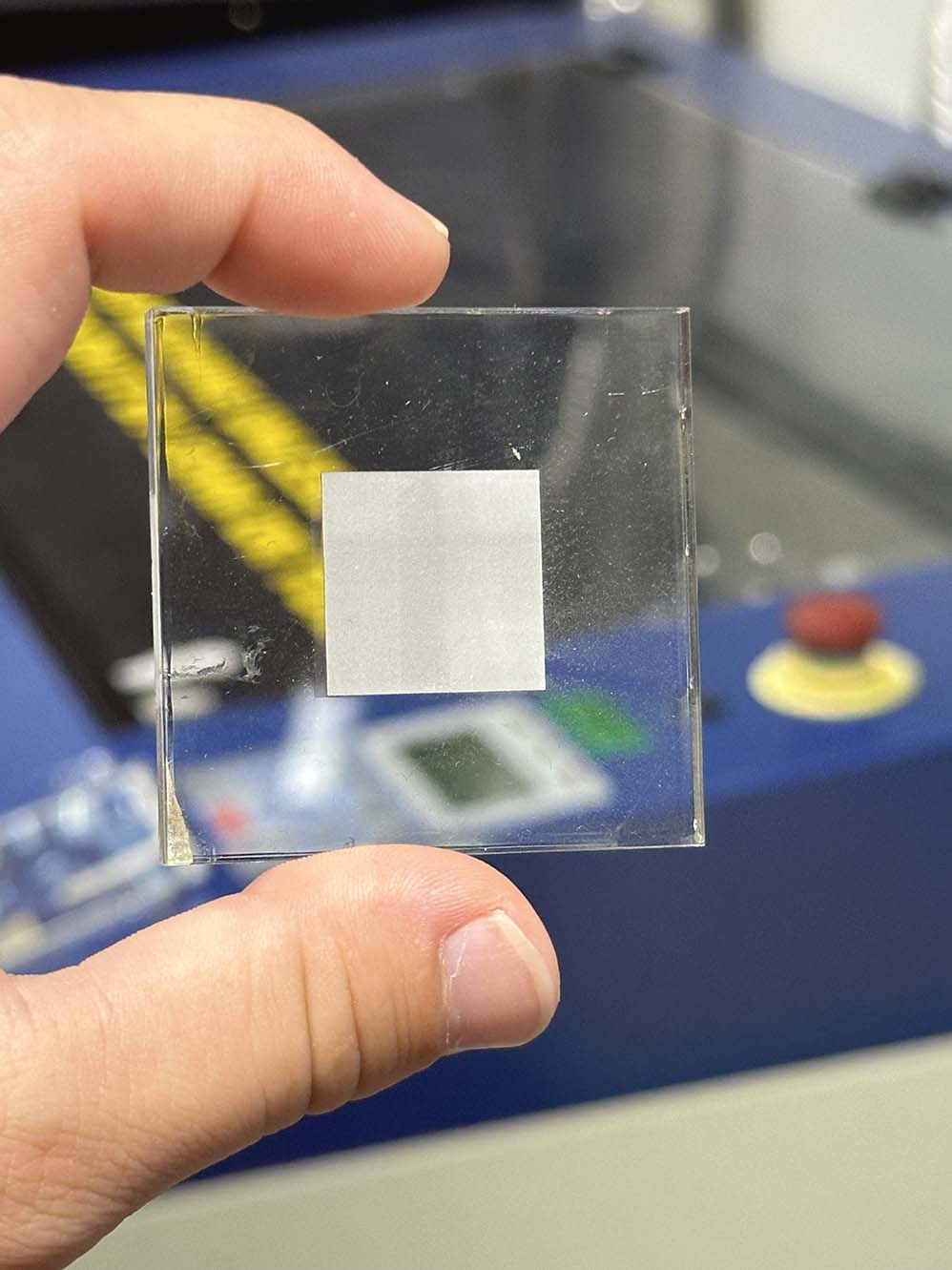
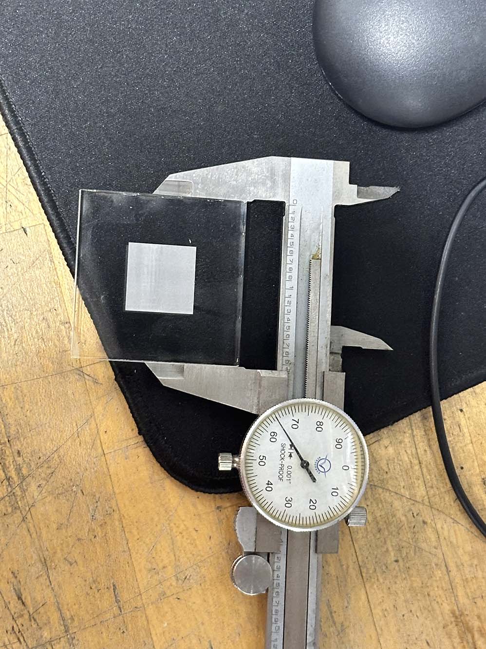
Another key component of the assignment is measuring the kerf of the laser cutter and designing around that constraint. The kerf is essentially the diameter of the focused laser beam - i.e. how much material it vaporizes with each cut. Considering the kerf will change depending on how accurately the machine is focused (which is not that accurate because we focus the laser cutter by eyeballing it), it is best to give a little bit of margin in the design tolerance. From the group assignment, we cut a 50mm square of acrylic and measred the true cut dimension of the square to be 1.965" (49.91mm), from this the kerf can be calculated to be 0.045mm. This tolerance is the expected value, and the group assignment laser cut acrylic square is shown below.
With the group assignment taken care of (noting that this week we also had many safety trainings as part of the group assignment), it is time to begin individual work! My proposed construction kit is a DIY plant stand. Pieces that vary by a geometric ratio can be organized to form plant stands of differing heights, widths, and aesthetics. The initial CAD is shown below, done in SolidWorks.
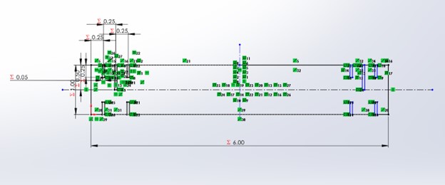
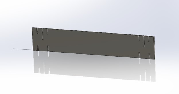
Something to note in this CAD, is that all of the design elements are utilizing global variables to enable the "parametric" part of this design. The nice thing about global variables is that I can tweak one or two numbers in a spreadsheet and the changes will propogate through the design. This adds a small effort cost up front for a lot of time saved in the future. The above units can be arranged to create the regular hexagonal structure seen below.
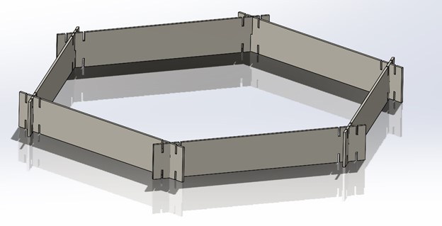
The idea is that smaller and larger hexagons can be joined to construct structurally sound plant stands to raise plants to different heights so they each get adequate sunlight. This first pass represents a good initial step in a baseline design. With a 6in length of the primary member connected at the central cuts, the point-to-point dimension of the hexagon is 10in. this is likely too large for practical applications of plants since 10in ceramic pots are almost certainly too heavy for the carboard material used to construct this design. The next iterations will feature shorter members so the point-to-point dimension does not exceed 8in and a taller member height since the assembly will build vertically at 0.5in per hexagon. The updated design is shown below.
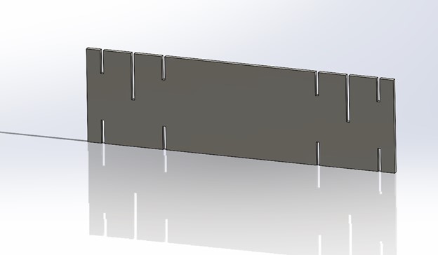
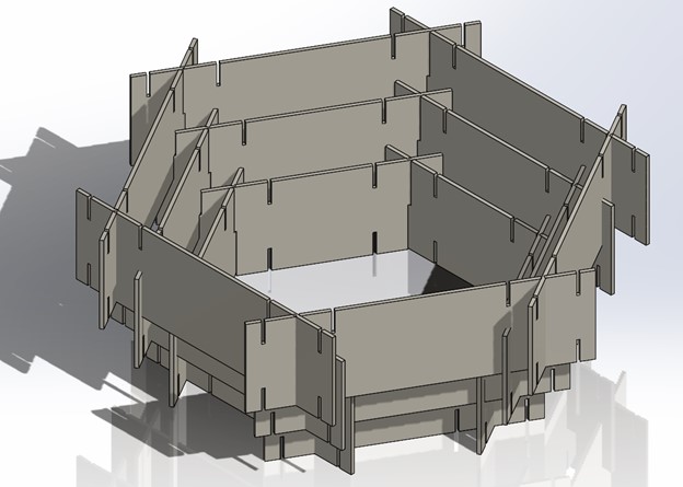
This can be assembled with other hexagons to create the following nested design, shown below to the left. Also, I changed my mind about the member height and went back to 1in heights. This decision was driven entirely by aesthetics, and the updated CAD is shown below to the right.
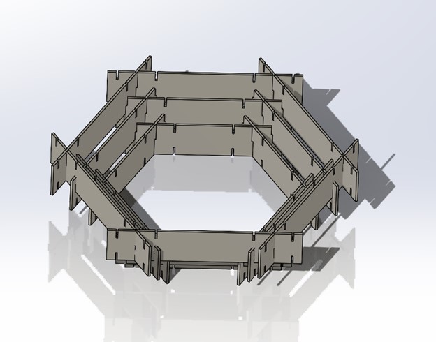
This is fun, but not very useful to hold plants up at the moment. Creating hexagonal plates to act as a platform will be the last part of the design. Adding in the hexagonal plate, we have a small version of a plant stand, shown below on the left. Other hexagonal plates can be nested inside the design, providing structural support, although they aren’t entirely necessary, shown below to the right.
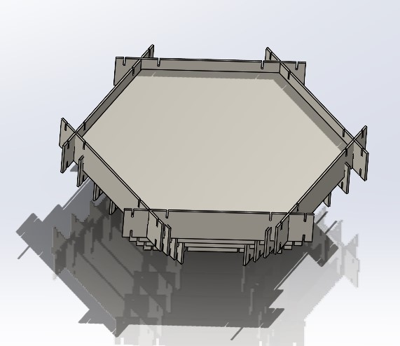
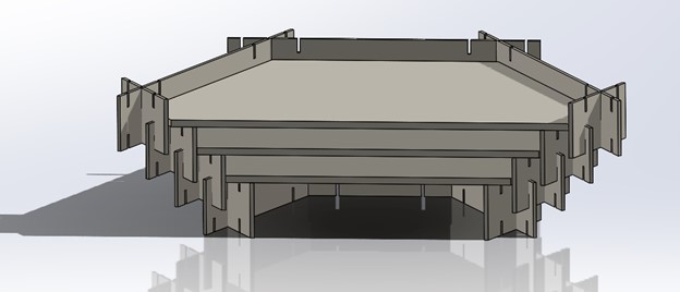
Note that multiple levels and layers can continue to be added on here beyond what is shown. The tipping risk increases as the height increases, but certain aesthetic freedom is granted with this design. Now that the design is ready to be prototyped, all of the sketches must be exported as vectors for the laser cutter to read. This process is simple – just “save as” the solid part as a dxf file. The preview is shown below.
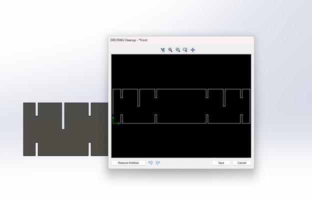
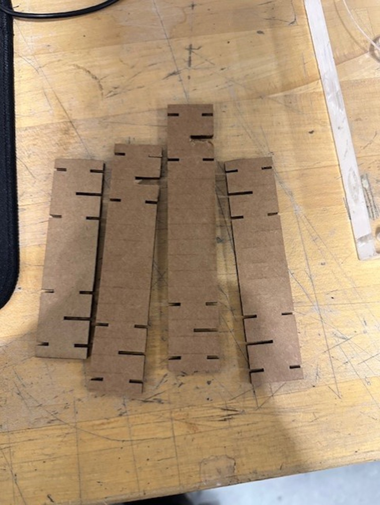 A trial of the cardboard construction was attempted, shown to the right. The board used was 1/8in thick, since this is the supplied shop stock, whereas the design was for 1/16in cardboard. Because of this, nothing could be assembled properly. Lesson learned here is two fold: (1) Neil was absolutely right about the magic of parametric design - I changed one entry to my table and that updated all of the cut dimensions while preserving the original ratios, and (2) always double check the dimensions of the shop stock you plan to use.
The design cuts need to be thicker to accommodate the thicker board. Good ol' trial and error helped determine the approximate size for the second round of cutouts, where an exacto knife and calipers were used to remove material until it could be joined and the resulting gaps were measured. A cut thickness of 0.15in was found to be best. Because of the 0.46mm laser kerf, the design cuts are set at 0.16mm in the construction kit drawing. This buffer should be adequate to accomodate the diameter of the beam and enable a smooth assembly process from here on out.
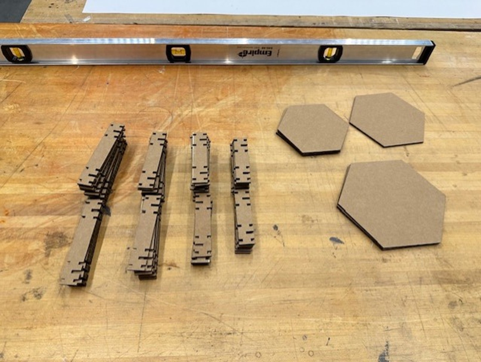
From here, a full complement of parts was created, making use of the entire cardboard sheet, and the resulting parts are shown below. On the left is the sheet just after it is cut and to the right is the parts organized by size.
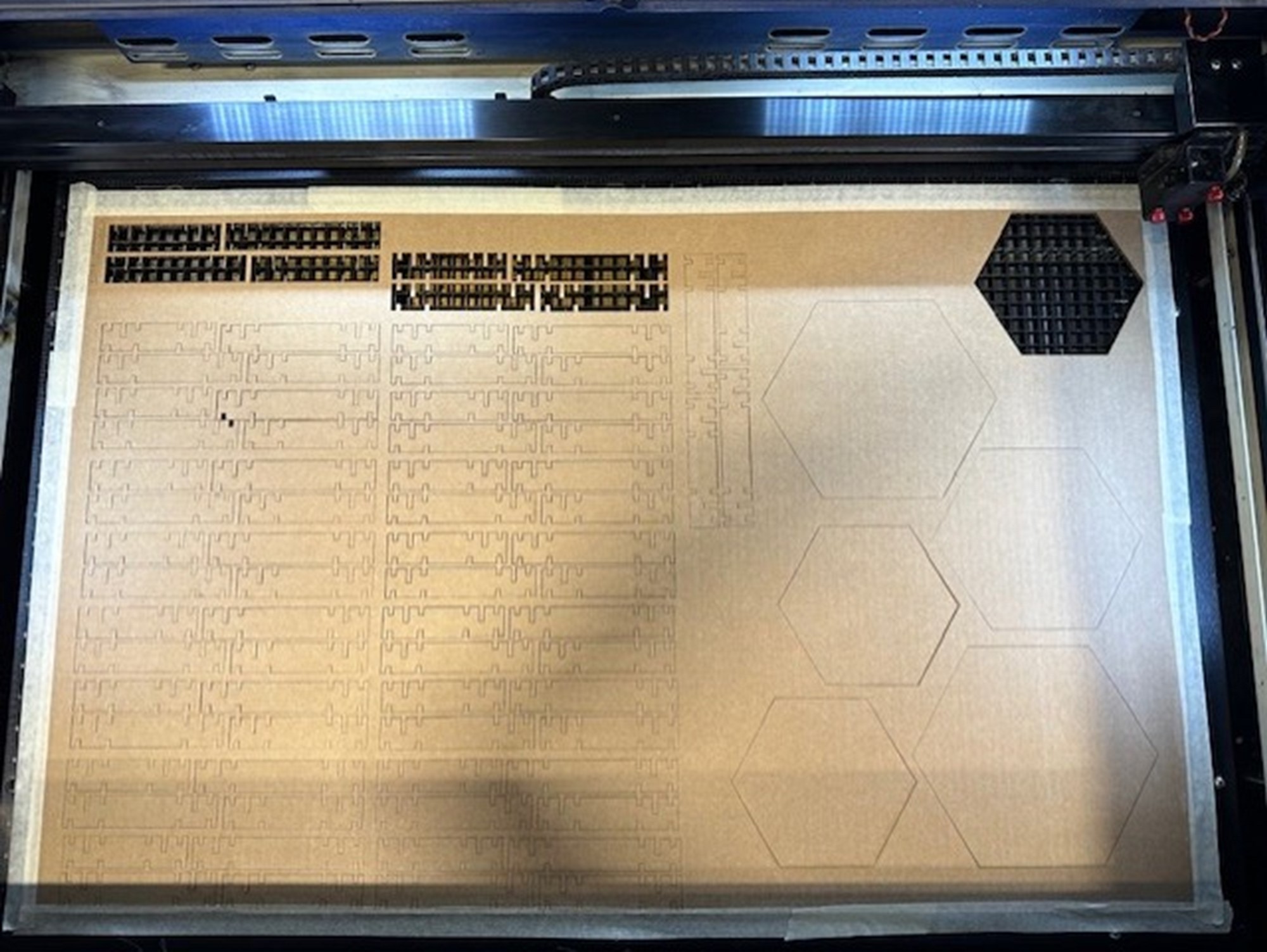
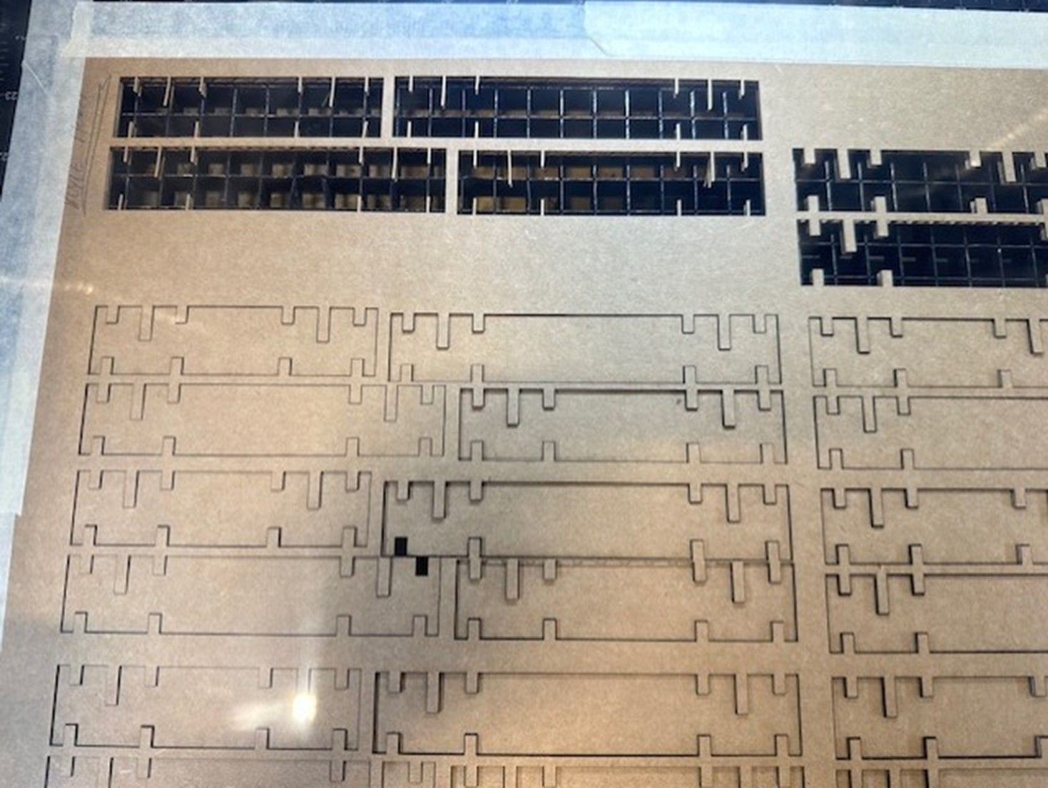
An interesting thing that I didn’t expect and couldn’t find a reason for its occurrence was that one of the parts encroached on another during the cutting process, shown below. Nothing major resulted from this, and all the rest of the patterned parts printed without incident, but the print file did not reflect this issue, so something ~fishy~ is going on. Nevertheless, the parts were within a reasonable tolerance so they can still be used. Hooray!
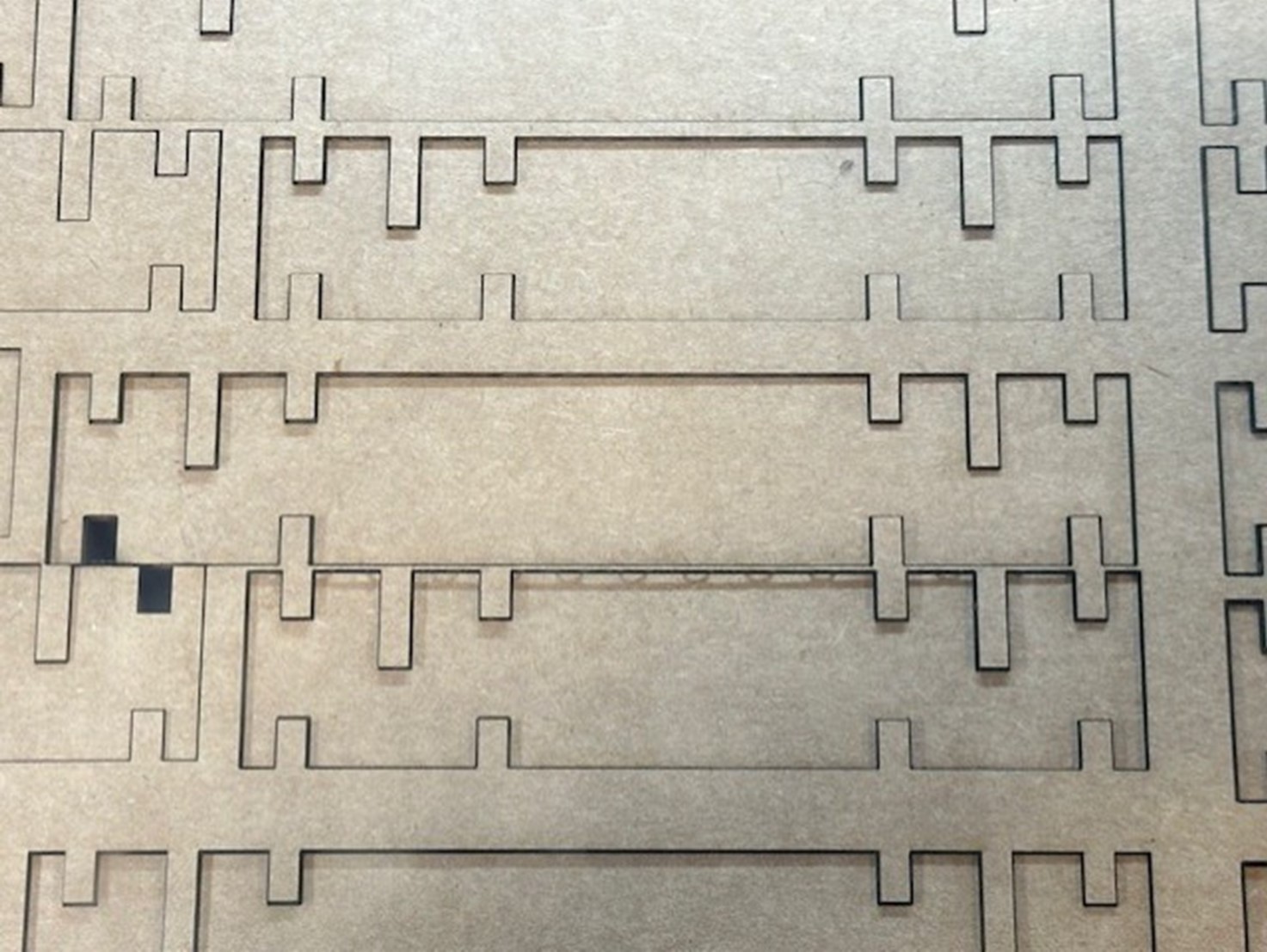
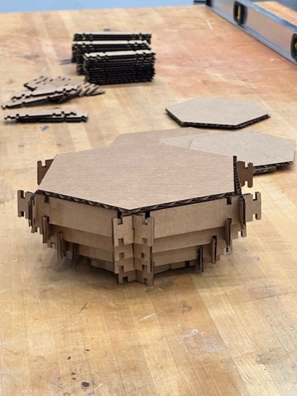
This assembly design worked well for joining cardboard at 90deg angles, but for the 120deg interior angles in a hexagon, the carboard was, for lack of a better term, unhappy. Some strong arming got the hexagons to join, but the design is far from perfect. Trying to find the balance between tight enough for a friction hold yet loose enough to not be damaged during the 120deg bend would be the focus of the next design iteration; however, this is where my time runs out for the week of training, vinyl cutting, and laser cutting (and there is a line now for the laser cutter so I don’t want to hold up my classmates from completing their tasks either). I am happy with the result! I would say it was 90% successful, and another few days could get me all the way there. I suspect this will be a recurring theme with the course.
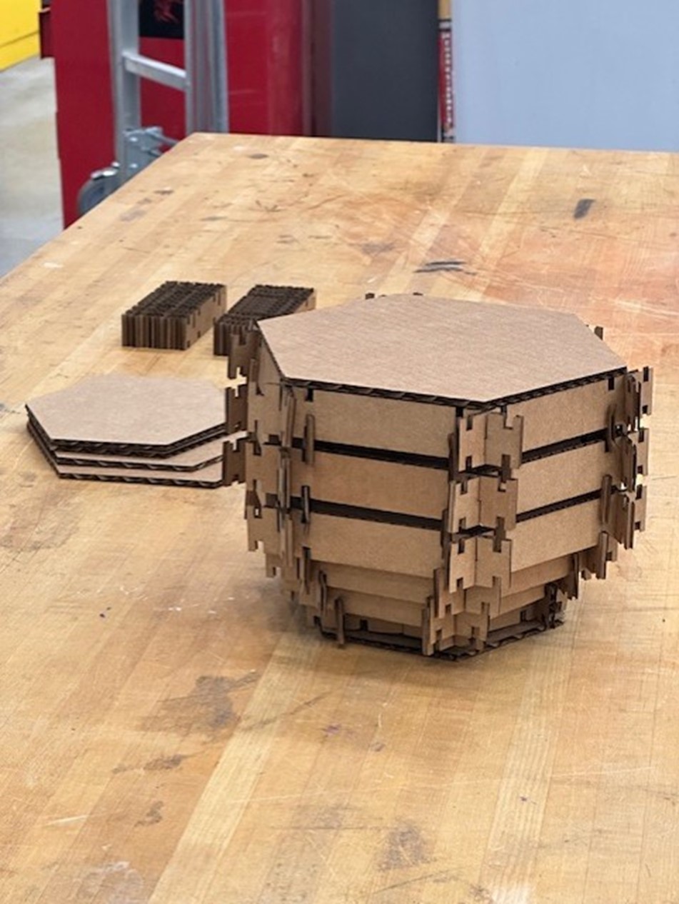
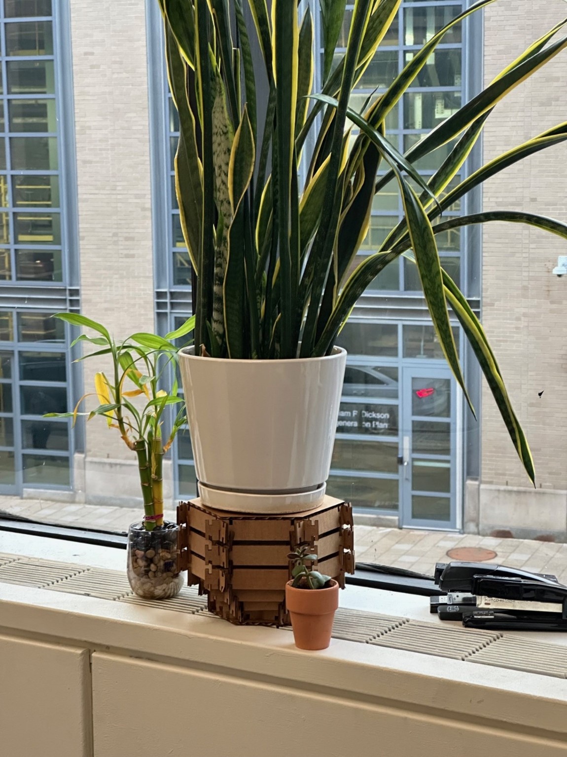
The final product is shown below! Different sizes and shapes of the plant stands can be assembled. The stands can even accommodate an impressive amount of weight from large plants! An overwhelming victory!
The files for this week can be found below:
- Download Solidworks CAD Hex 6in
- Download Solidworks CAD Hex 7in
- Download Solidworks CAD Hex 8in
- Download Solidworks CAD Planter Wall 4in
- Download Solidworks CAD Planter Wall 4.5in
- Download Solidworks CAD Planter Wall 5in
- Download Solidworks CAD Planter Wall 5.5in
- Download DXF Hex 6in
- Download DXF Hex 7in
- Download DXF Hex8in
- Download DXF Planter Wall 4in
- Download DXF Planter Wall 4.5in
- Download DXF Planter Wall 5in
- Download DXF Planter Wall 5.5in
