Molding and Casting

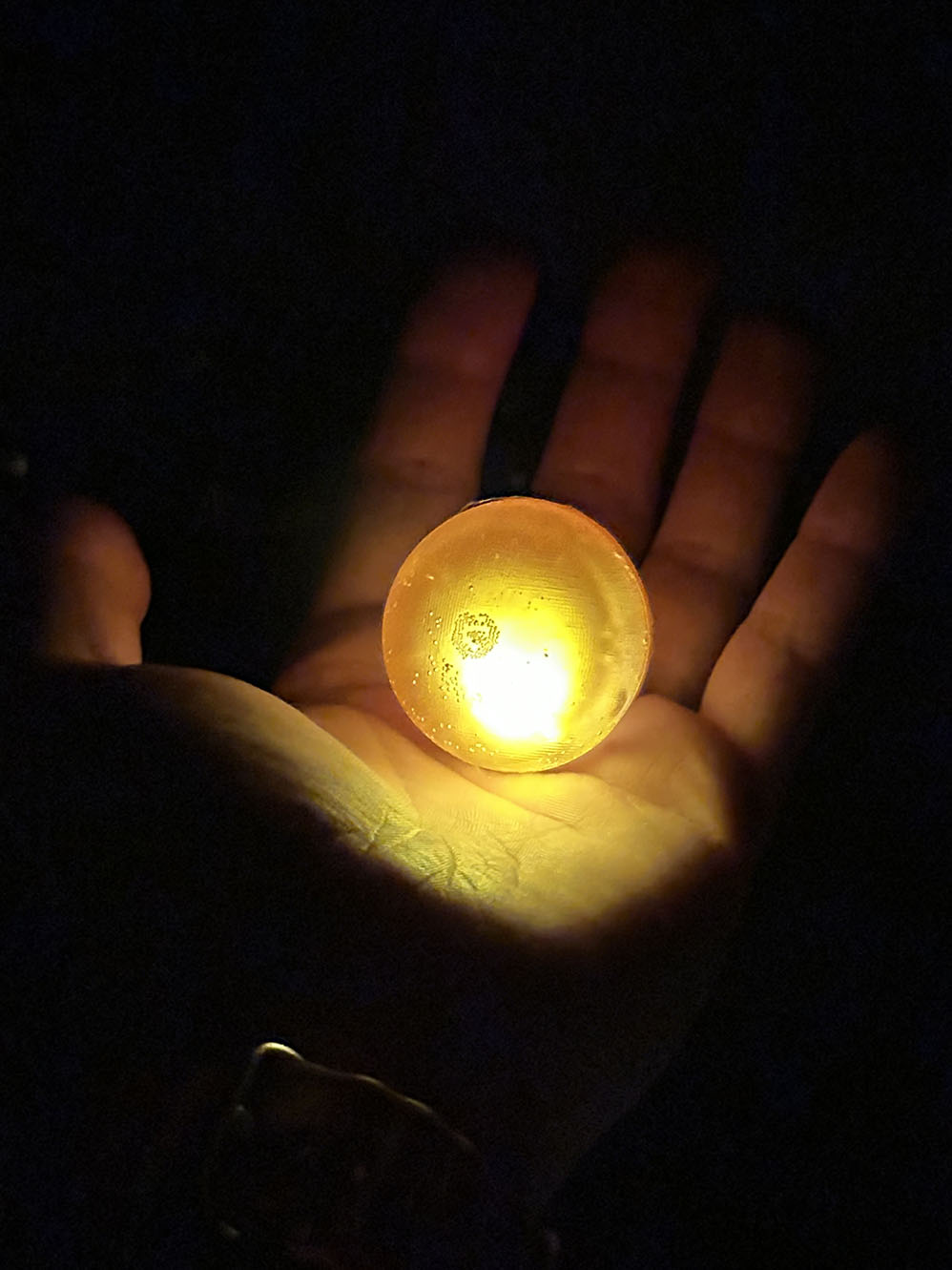
The idea this week is to make a the a little glowing sun. To do this I will simply cast a hollow sphere and fill it with a tiny pcb (that I now know how to make and program!) that activates a few LEDs. This week has a lot of long wait times for things to cure, so making something cool that combines a few simple elements will work to my benefit here.
"The power of the sun in the palm of my hand" vibes.
As always, we start with the group assignment. Here there are two main parts to the group work: making a mold and casting in it. We have a few options for making a mold: CNC a wax block using the benchtop Genmitsu 3-axis CNC mill or using a SLA (resin) printer. Either way the goal is to make a mold with no visible lines of the manufacturing process. I am rather comfortable with the process of 3D printing, so I think CNC milling will be more worthwhile. Alfonso emphasized the importance of safety this week while using the machine and stressed that we must work in pairs. I have heard horror stories of students working late nights with CNC mills and getting their hair pulled in so I figure these are wise words to live by. The process for CNC milling is pretty straightforward: take your design in fusion and add a few adaptive and parallel passes in the fusion manufacture tab and boom. Done. The actual process for securing the wax stock is a little more questionable, we hot glue the stock to a copper plate and then clamp it down, but hey if it fits it ships. We did a test mill of a pyramid and just used rough adaptive passes so as to not take too much time. The result is shown below, and it only took about 10 minutes to mill!
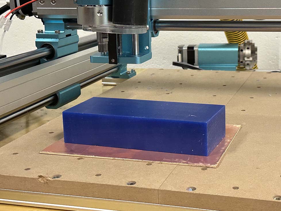
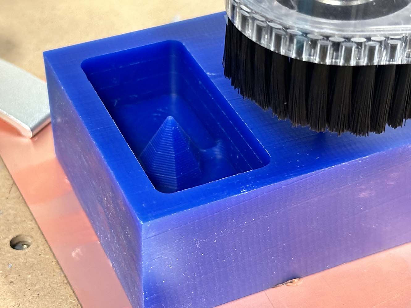
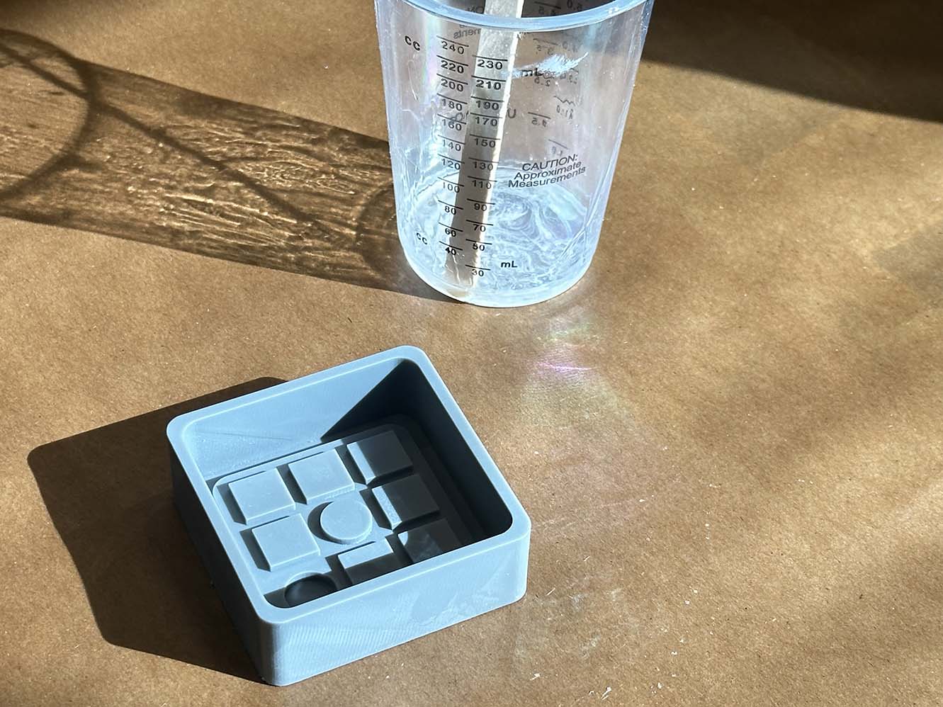
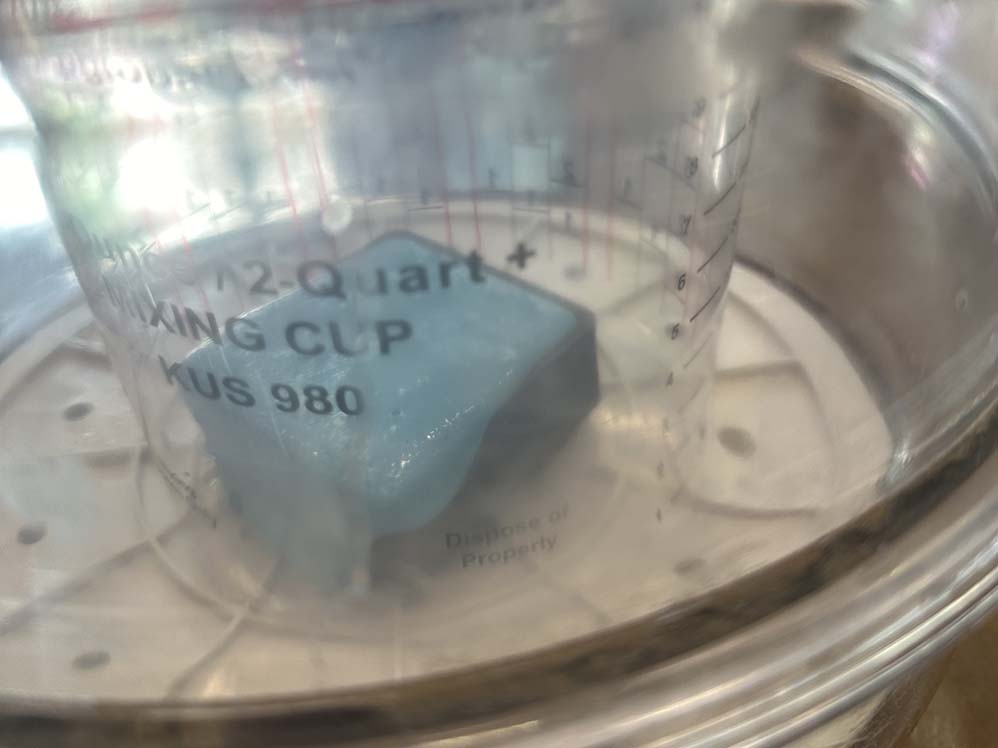
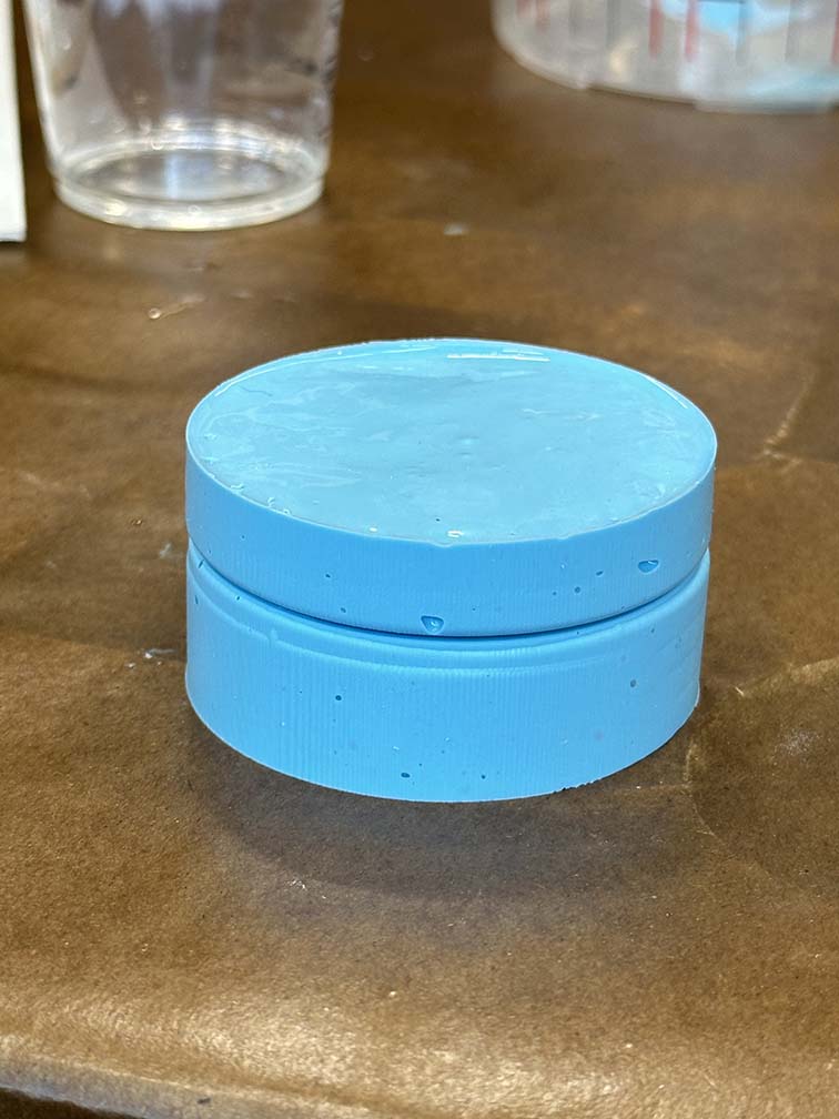
The other side of the group assignment is to do a test cast. Here we reviewed the safety data sheets for the materials we will be using: Oomoo (which has an incredible name I gotta say) and smooth-cast (slightly less incredible name but oh well). Oomoo is relatively harmless as a two part silicone, obviously don't eat it or get it stuck in your eyes, but mistakes with Oomoo are forgiving. The liquid plastic is considerably less forgiving. The reaction is highly exothermic, so it will burn you, and the fumes are nasty. This stuff is toxic and needs strict adherance to PPE guidelines. The process for casting both the Oomoo and the plastic are pretty much the same: you mix equal parts of the material, evacuate it in a bell-jar chamber to remove bubbles, then pour it slowly into the mold to further reduce pockets of gas in the cast object. Below is the above process for Oomoo (in blue) from a SLA mold of the CBA logo. In this case, I was not able to get good images of the process due to the materials being used. Maintaining proper Body-Substance-Isolation with my gloves and not touching my phone was a safety issue, so below is a good picture of the mold before casting it and then the overflowing Oomoo in the vacuum chamber after I placed it and removed my gloves to let others finish the process.
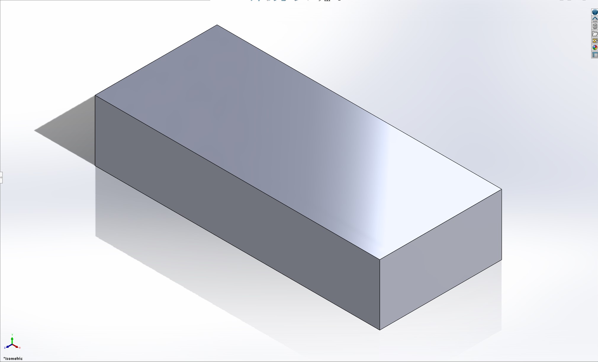
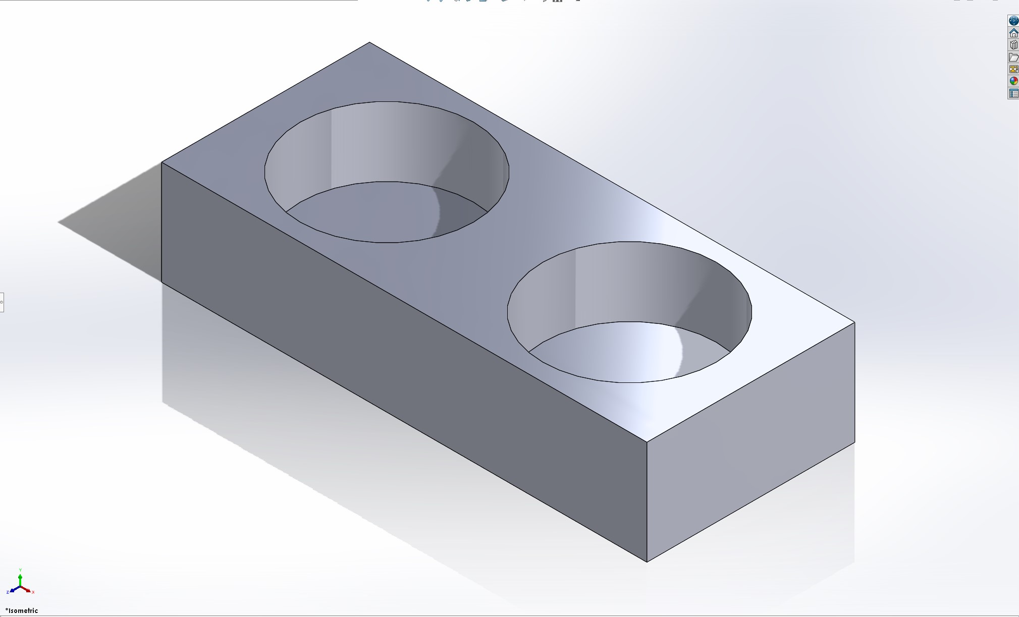
Moving on from the group assignment, lets start by CADing the stock we'll be working with. This week, we are machining our molds out of wax. We need to make a wax positive so we can cast a silicone negative to use as our mold to cast the final product as a positive. Without being too negative, I'm positive that this process will negatively impact the positive state of my negative emotions since the psotive-negative transitions are postively confusing. Since I need to cast a hollow sphere, I actually do need both a positive mold of the outer sphere surface and a negative mold to hollow it out (I am so sorry, this part of the process is going to be a lot of positives and negatives). I'm planning to cast the part twice to make the two hemispheres and make one complete sphere. The stock has two wells that will hold the silicone to make the negatives (or I guess in my case the negative of the sphere and the positive of the inner sphere). From here the sphere can be added and the real thinking can begin.
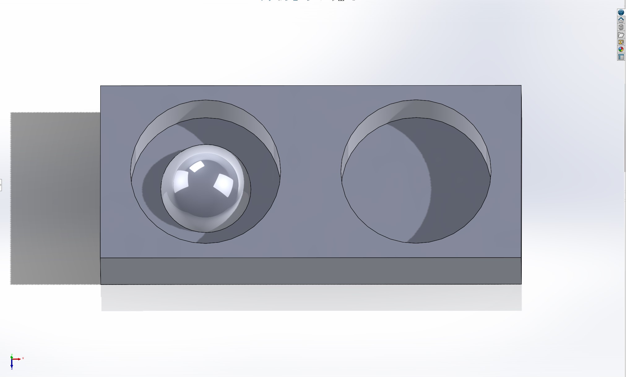
In order to get the two halves of the mold to align properly, I need to add some physical structure to ensure concentric alignment. There are a few ways of doing this: (1) have a bounding box for the molds that aligns the external surfaces, (2) tabs on the inside that fit into corresponding alignment slots, or (3) a lip or collar that aligns the mating surface of the two molds along the joined perimeter. I'm opting for the third option since it is easy enough to implement and Neil seemed to have a strong bias for it in class. I've learned that when I default to what Neil reccomends things tend to work out a little bit easier for me. Funny how that happens, right? After adding the alignment collar I added the negative depression for the inner sphere and some tabs to eventually mate the two cast hemispheres together. The CAD for that process can be seen below.
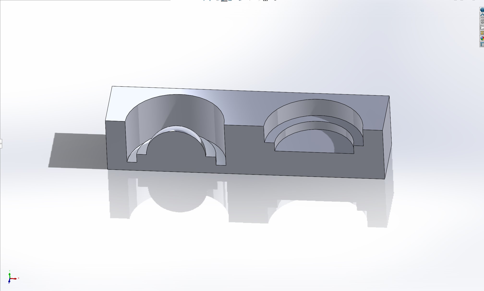
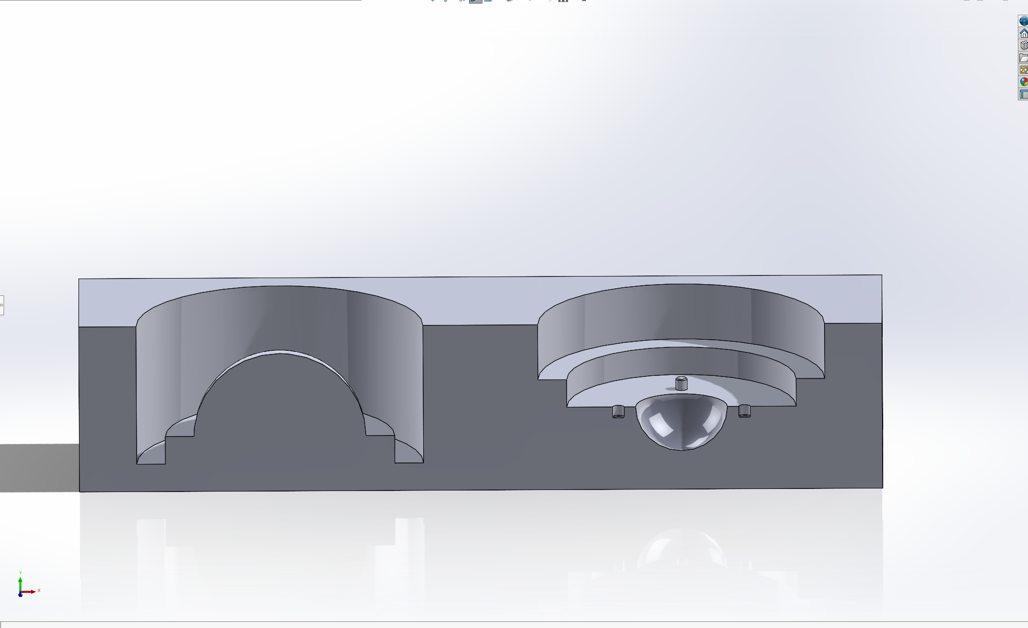
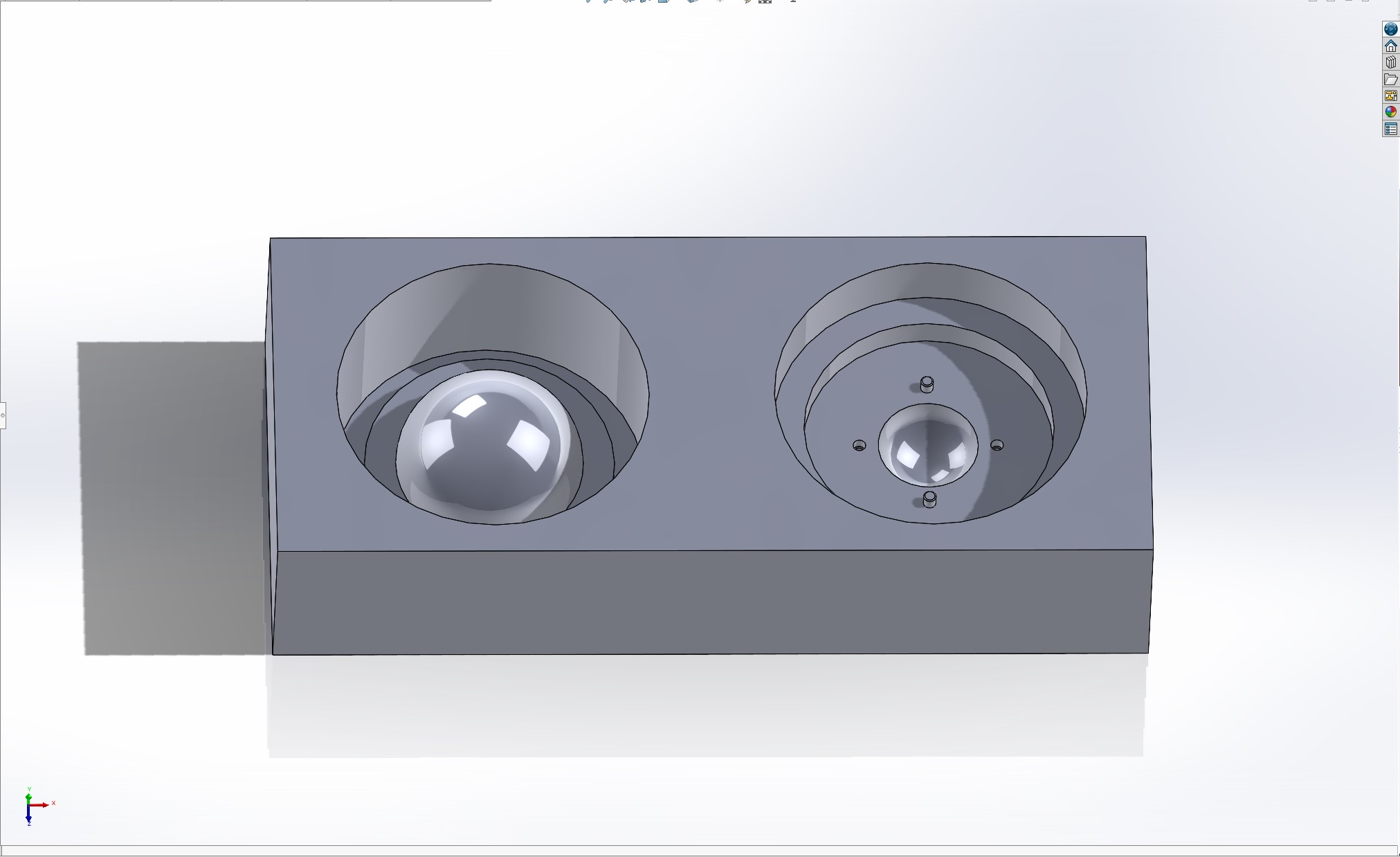
Now that we have a mold, it's time to migrate this to Fusion to create the path planning for the mill. Solidworks does have a comprenesive suite for CAM; however, all of the instruction for this process was given to us in Fusion so that is the best documented for our specific use case. Because of the thorough documentation, and because I should honestly become more familiar with Fusion to be a good engineer, I'll export the model as a STEP file and send it on over to Fusion.
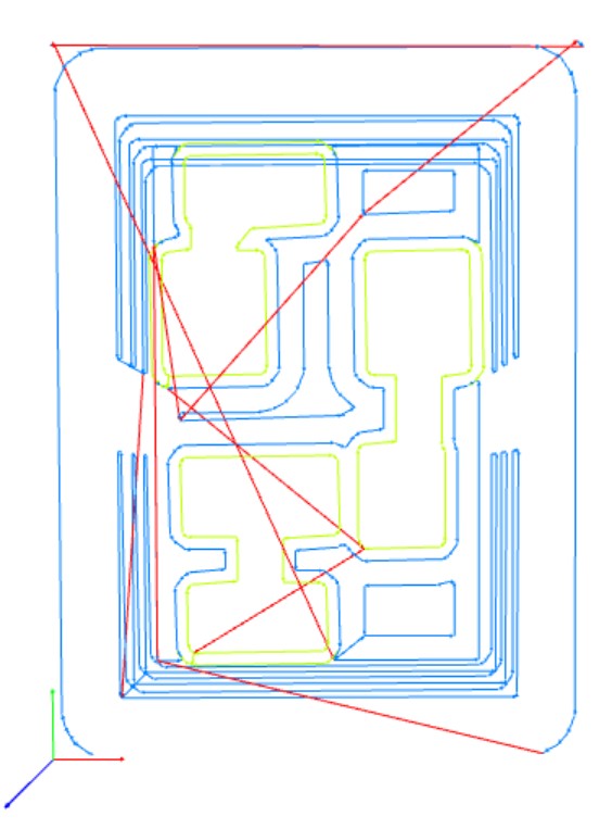
Fusion is easy enough to use, but it took me a long time to learn how I can adjust the orientation of my model (longer than I care to admit), but we got there, and now it's time to path plan. The machine we are using in the CBA section is a Genmitsu 3-axis CNC mill with a 0.25" flat head endmill and a 0.125" ball mill. The quarter inch bit can be used for some adaptive clearing rough passes, and the eigth inch ball I'll use for the parallel finishing passes. The parameters for this are documented on the class site in the CAM recitation notes, and I followed that as a guide to get me started. Below are the Fusion CAM paths for this first attempt.
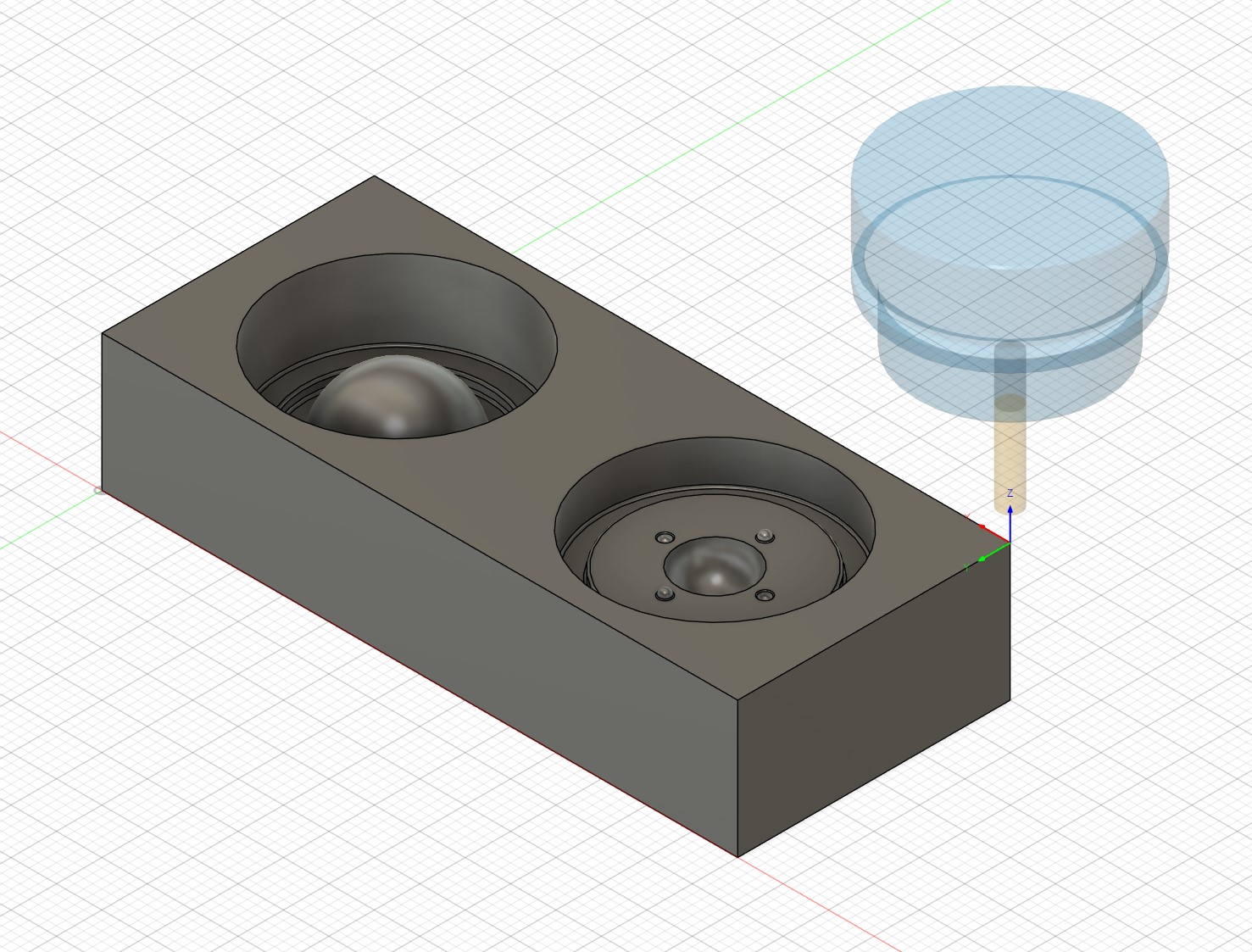
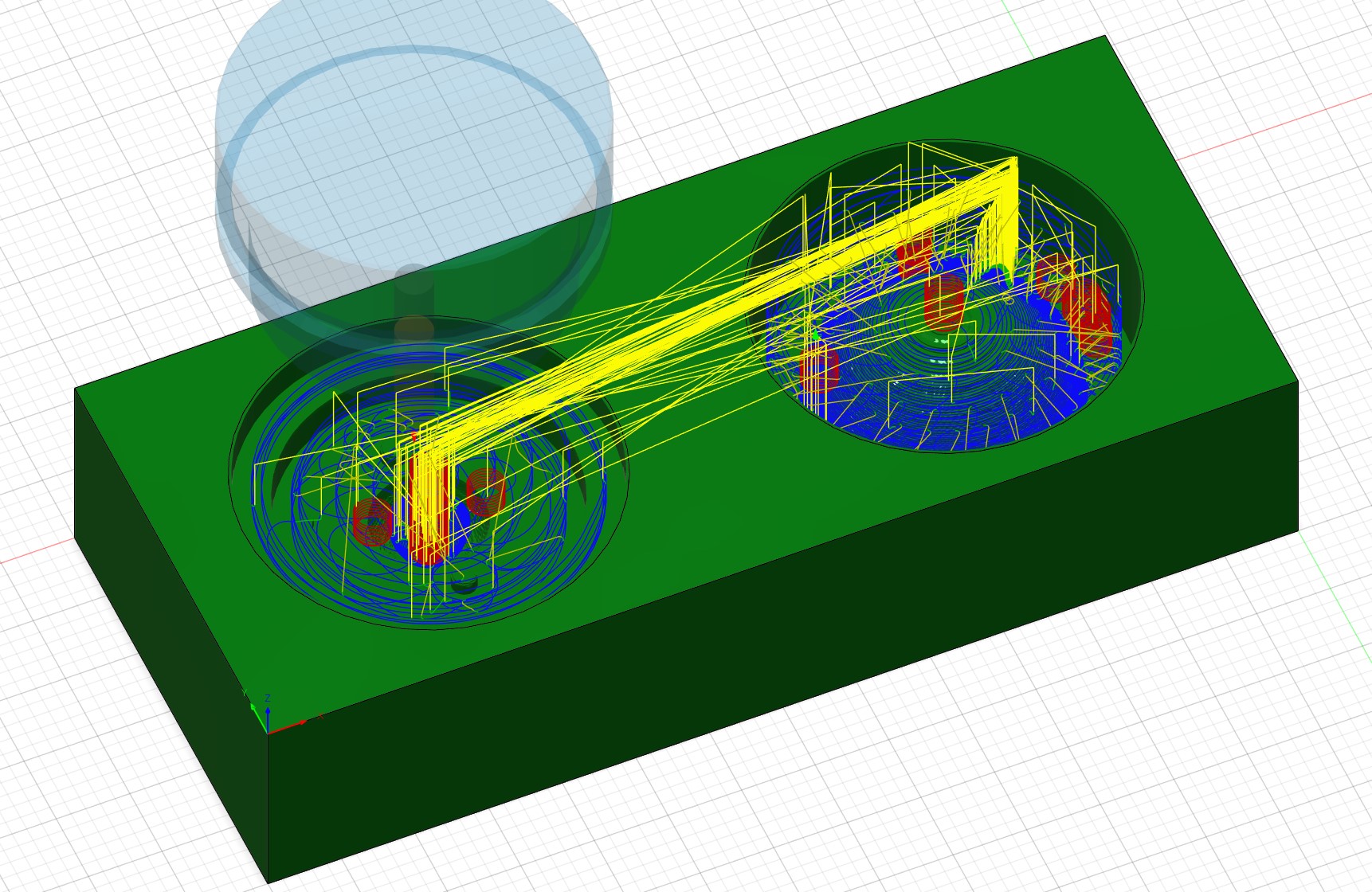
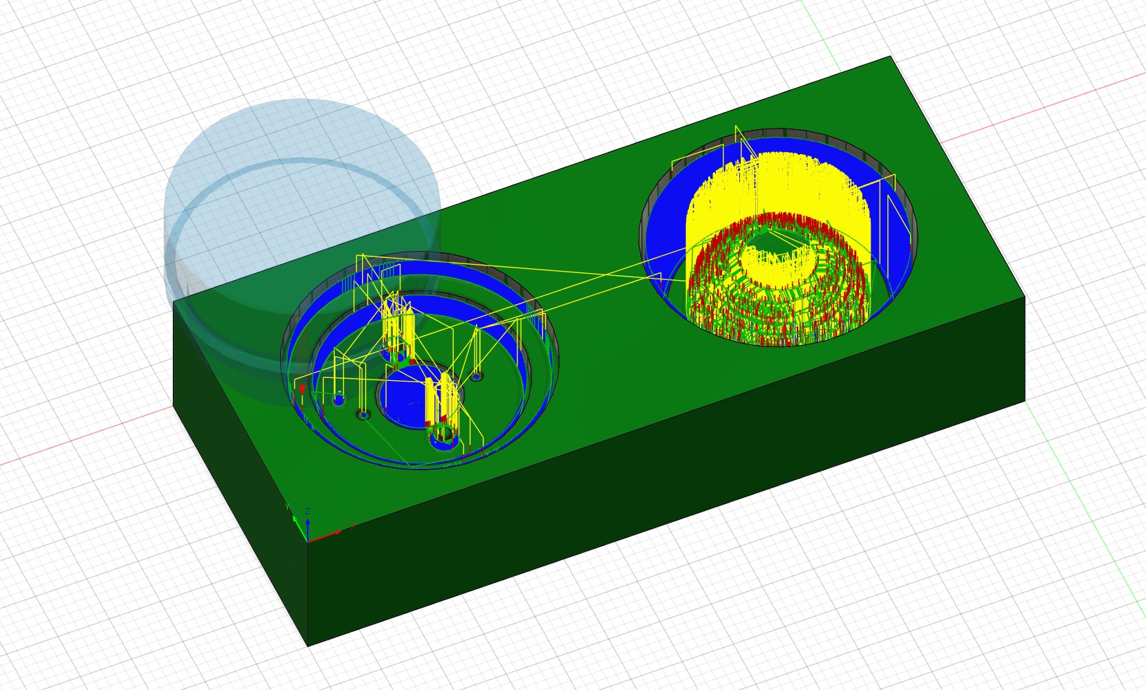
Now an interesting thing here is that the surface fininsh of the parallel passes is really not that good, and there are several sections where material is being either left from the adaptive passes or being carved out for not apparent reason. I also noticed that there were a lot of parts of the mold that were rather inaccessible to the endmill (the deep well-like collar and the tabs) which needed to be fixed. So I went back to the Solidworks to update the model to be a bit more CNC friendly. This redesign is shown below, and features an inverse of the original collar placement to make the access of the parts better. The redesign also features rounded tabs for alignment and filleted edges for the mill. This part should, in theory, be completely replicatable by the CNC and it's physical limitations.
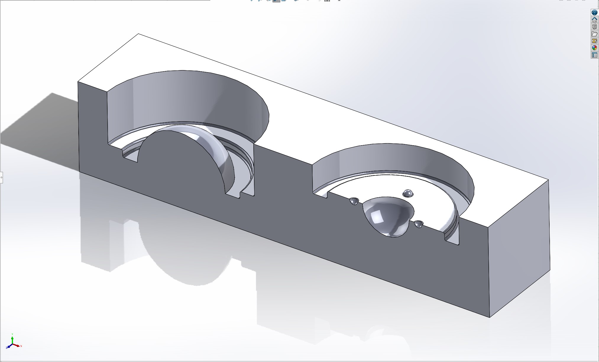
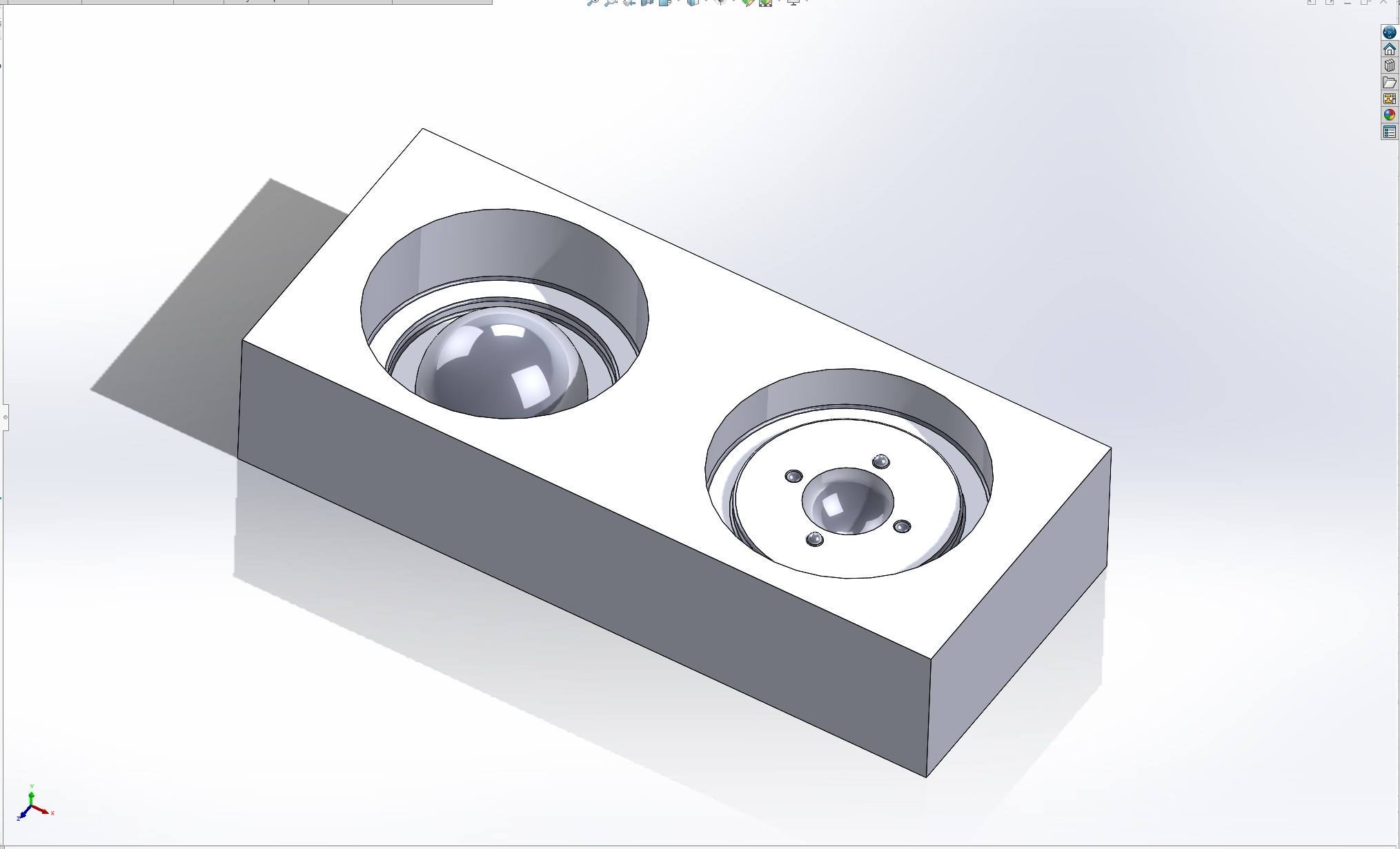
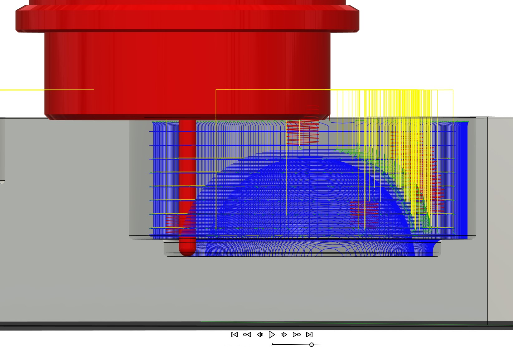 Taking this back to Fusion, the same CAM passes are implemented and simulated to check if I'm ready for exporting the GCode. Unsurprisingly there is an interference with the mill chuck and the wax stock. What is surprising, though, is that it's only overlapping by a few dozen mil or so. This is easy enough to adjust - just raise the well of the sphere positive by about 0.05" and call it a day. The simulation interference is shown to the right.
After raising the sphere by 0.05", the simulation was rerun and, lo and behold, the interference has vanished. The adaptive clearing rough passes are shown below alongside the parallel passes and a zoom in of the fine detail capability of this job. The adaptive pass takes only 11 minutes to run, while the perpedicular set of parallel passes takes almost an hour. Since I'm getting a jump on the assignment, there shouldn't be much competition for the machine - yet.
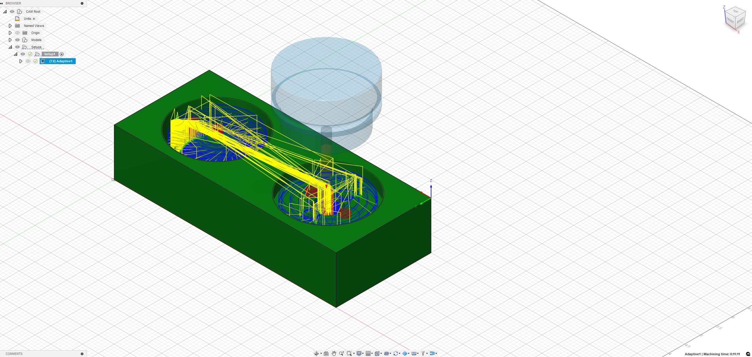
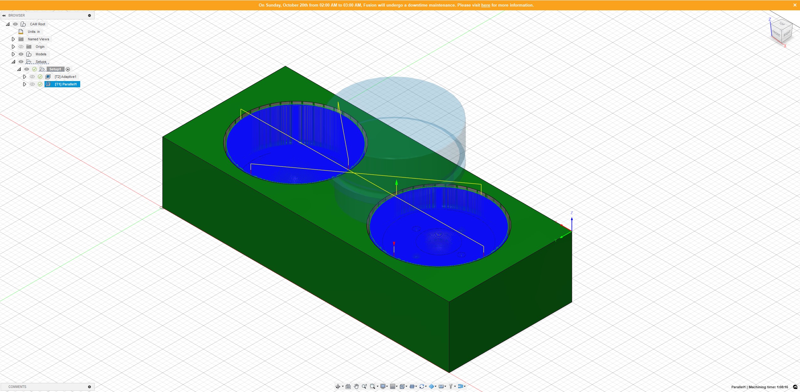
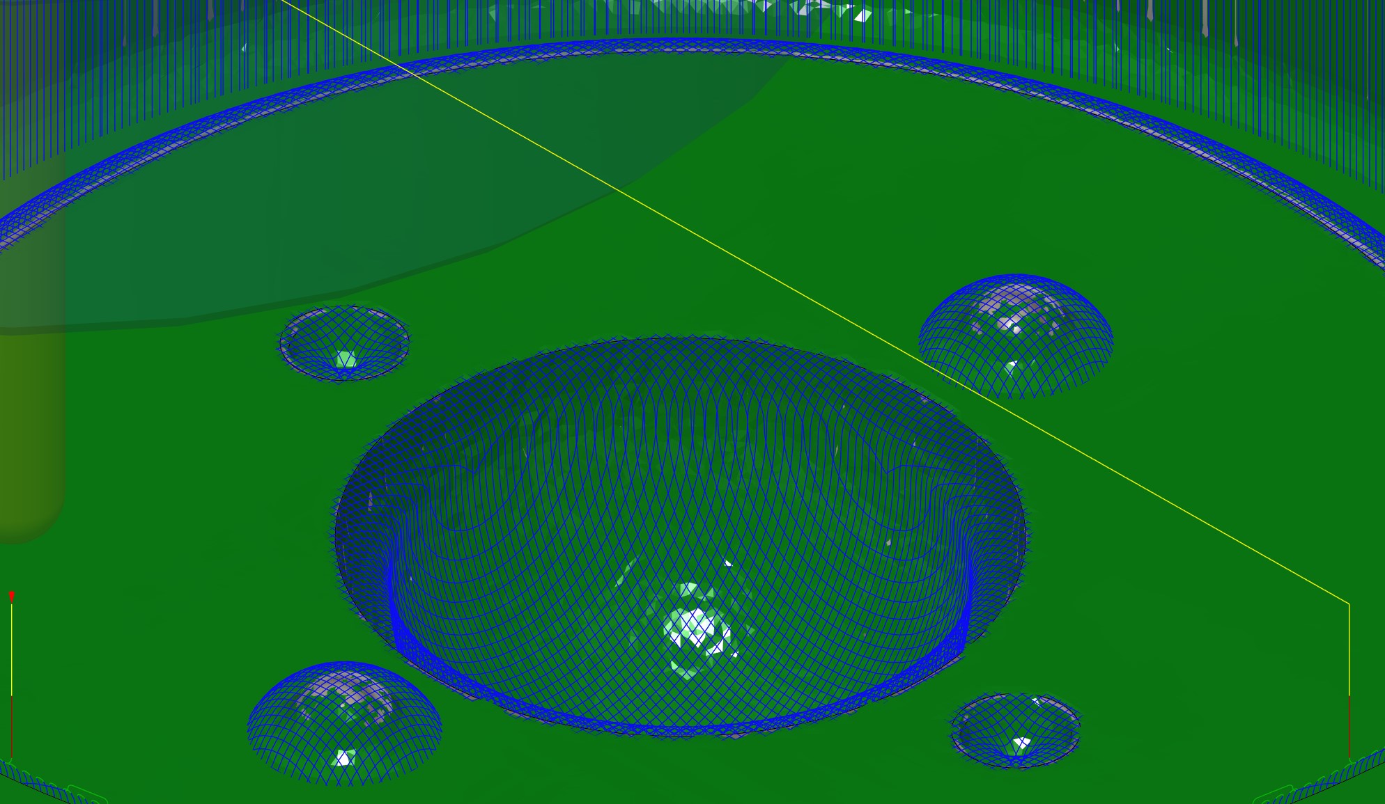
Since the intereferences have been taken care of and all seems to be reasonable for the Genmitsu, it's time to export the GCode and megin the wax mill. Also, for your viewing pleasure, enjoy a 6 minute video that shows the entire CNC toolpath being simulated. It's not very efficient (it goes back and forward between the two wells quite a bit), but this should only add a few extra minutes to the job so to me it's not worth reworking the path planning to mitigate. For now we leave it as a quirk of me not really knowing what I'm doing.
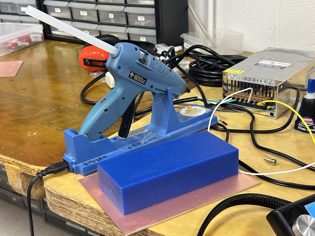
Ok let's mill this bad boy. To dropkickstart this process, we need to hot glue our stock wax block to a copper plate before claming it down in the mill (I promise these are the real rules I'm not just making it up). After that we can align the mill to the coordinate system origin of the GCode. It is important to make sure these two coordinate systems (that is, the one for the machine and the one in your GCode) are in agreement. If not you'll have funkiness (bad). I defined the origin as the front left corner of the wax stock. To align it with the milling bit and zero the coordinate system we just eyeball it. The true chaotic neutral alignment for CNC. Below is that process.
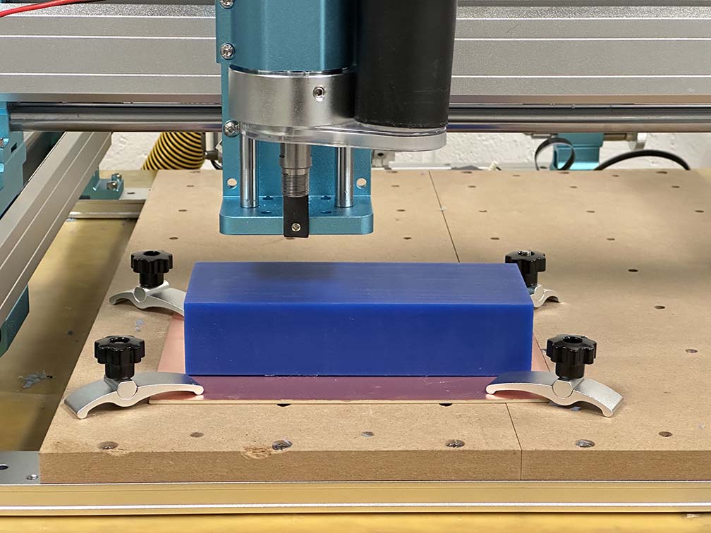
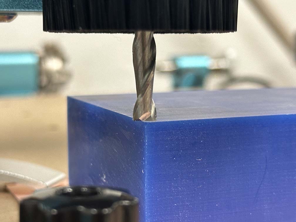
With that done, we can run the job. The adaptive passes are done first where the majority of the material is milled away rather quickly using the 0.25" flat endmill. After the adaptive passes we switch out the bit for the 0.125" ball endmill, rezero the z axis, and run the parallel passes. The parallel passes take considerably longer and carve out less material but do so in a fine step pattern that leaves behind a smooth finish. The adaptive and parallel passes are shown below with a zoom-in of the surface finish I was able to get for my wax mold.
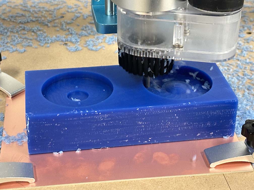
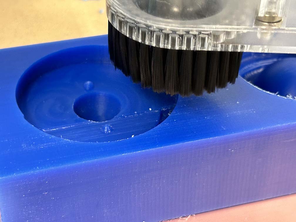
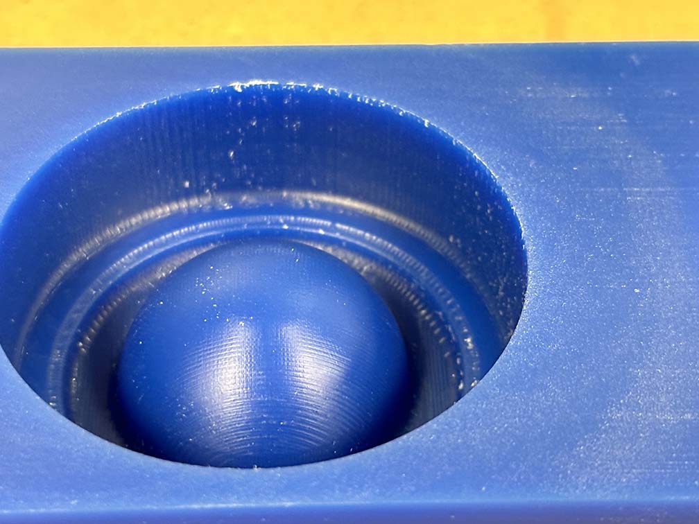
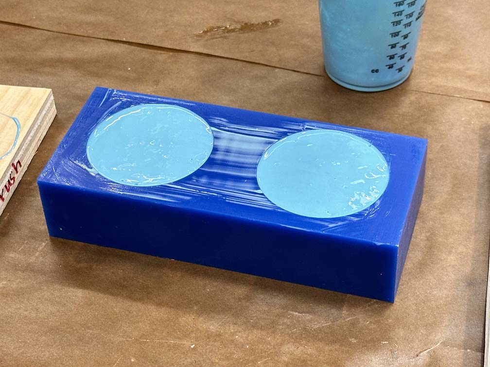
The finished mold is shown below. Now that we have a mold of the postive (and negative), it's time to cast the silicone mold for the final part. Here we are using oomoo - a two part silicone that is very easy to use.
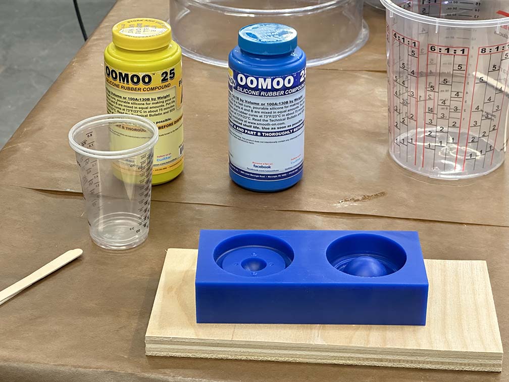
Oomoo is a very user friendly substance - you mix equal volumes of liquid together, stir, and cast into your mold. Easy. The trick is the techniques required to reduce bubbles in the final cast. That part is an art. To try and mitigate the bubbles, the mixed oomoo is placed in a vacuum chamber and depressurized for a few minutes. After that it is poured into the wax mold in a very long thin stream to try and force bubbles to collapse on the way down. The remaining silicone can remain in the mixing cup and can be used as a measure of how cured the oomoo is.
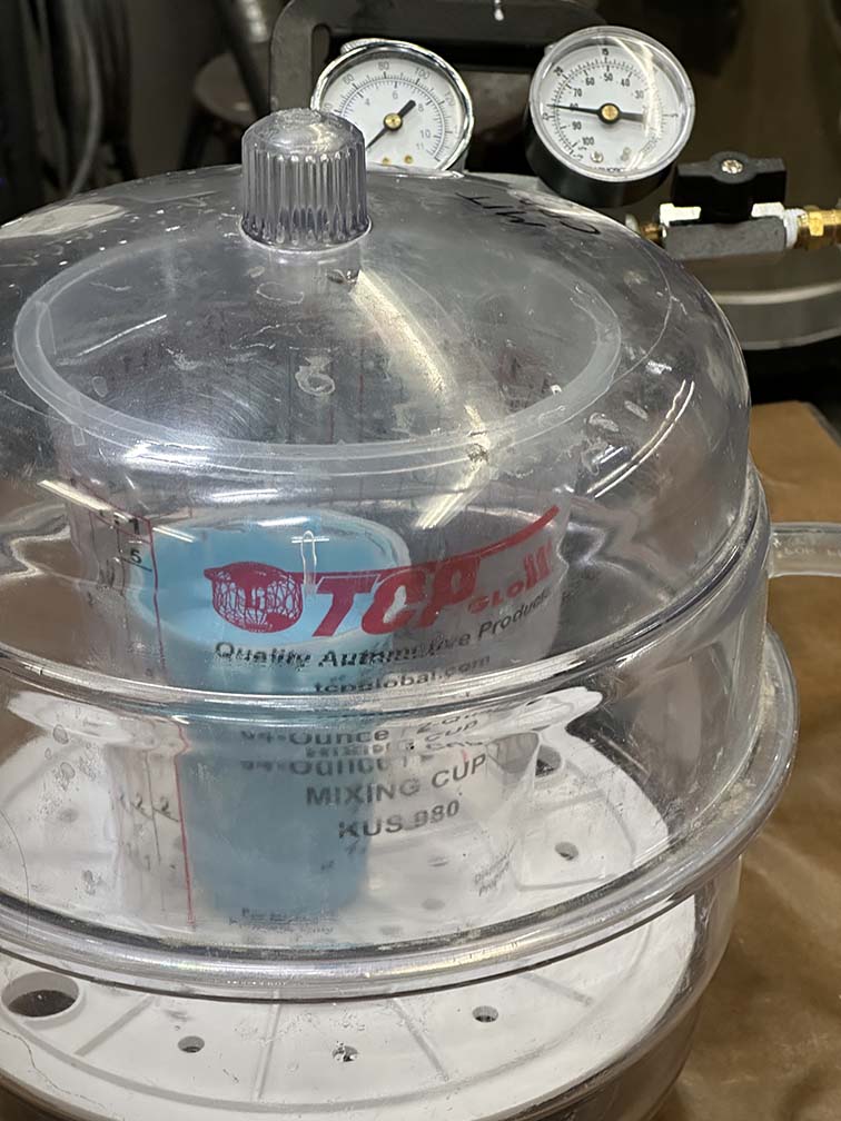
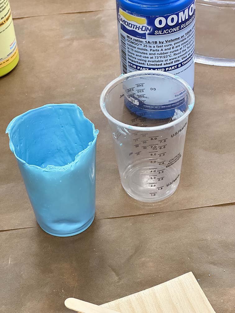
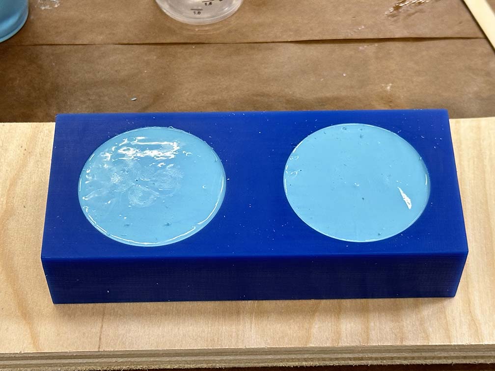
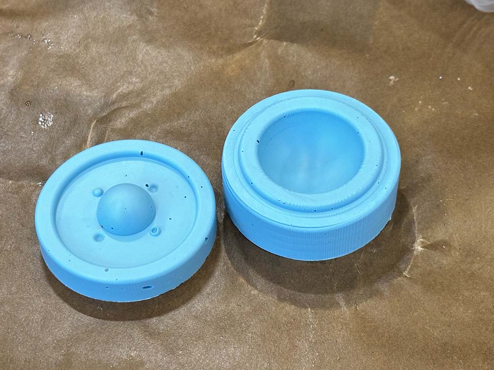
After a few hours the silicone is ready for release (as dictated by the cup cast). The first mold looked kinda like swiss cheese, but the important aspect is the outer surface of the sphere, which in this case is largely intact. This also works well as a proof-of-concept for the two part mold fitting together, which it did rather nicely. Neil doesn't lie about his suggestions that's for sure.
With this it's time to start casting the final part in plastic. Here we are going to use the two part "liquid plastic" that has bottles which look identical to the oomoo bottles. Considering how much more of a health hazard the liquid plastic is, this seems like poor product design, but who am I to judge. I want to dye the plastic orange to make it look like the sun (or a star of sorts), and while we dont have any liquid plastic dye in the lab, Marcello (god bless the TAs yet again) reccomended using food dye. I looked it up and pretty much every online forum says not to do this. Let's do this.
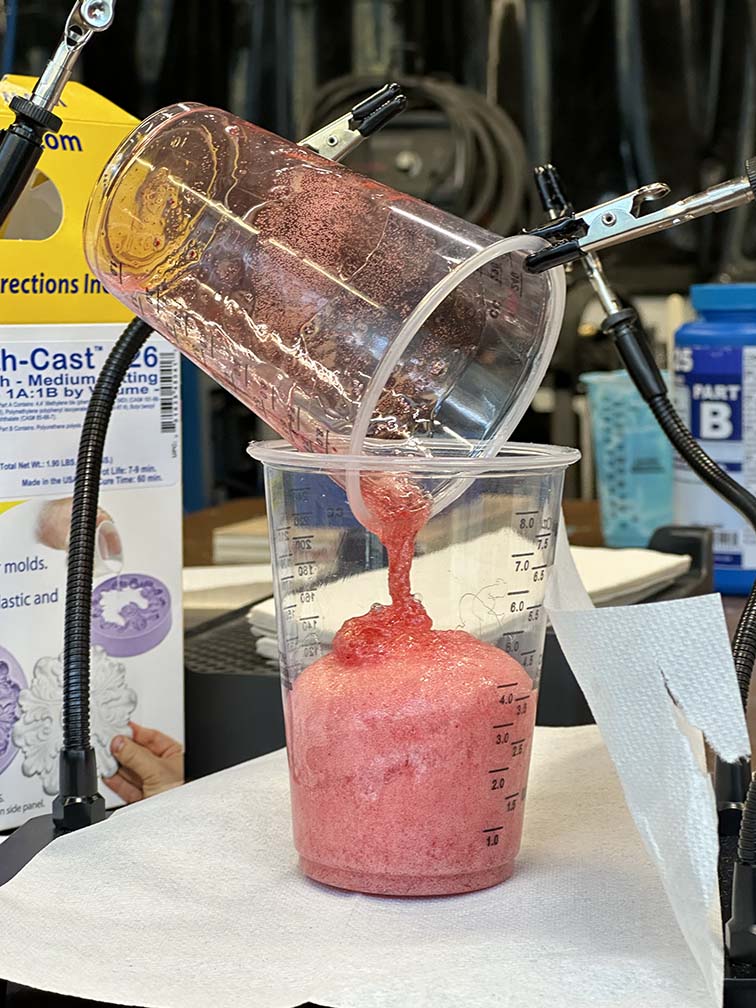
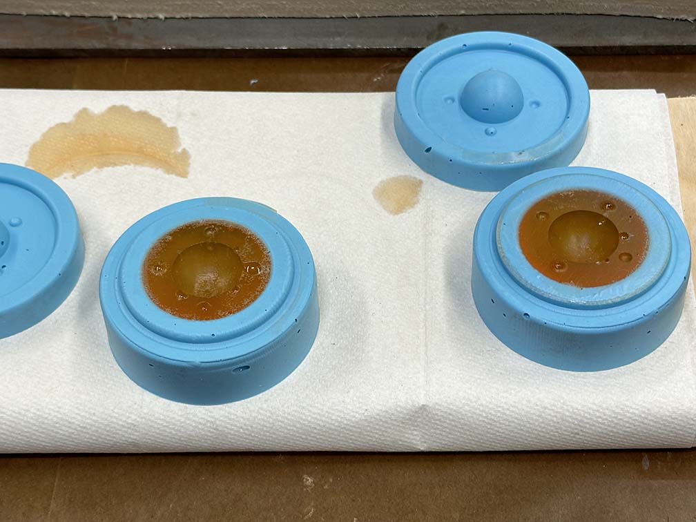
Rad as hell. I'm sure this can be fine tuned a bit to get the disired effect, but I am a big fan of the Icee looking liquid plastic. Big vibes. Also liquid plastic doesn't follow the conventional food dye coloring rules (i.e. to make orange you mix two yellow and one red), so we are experimenting with color as well. After watching the plastic Icee come to life, I realized the fizzing is caused by water in the dye boiling as a result of the exothermic hardening reaction. Super neat. In order to mitigate this a little, pressure can be applied to the molds to reduce the volume of the bubbles. The next plastic food dye attempt is shown below. The color was altered also to be just the drops of yellow. This did give a more electric looking orange, but we can work with the data and move on.
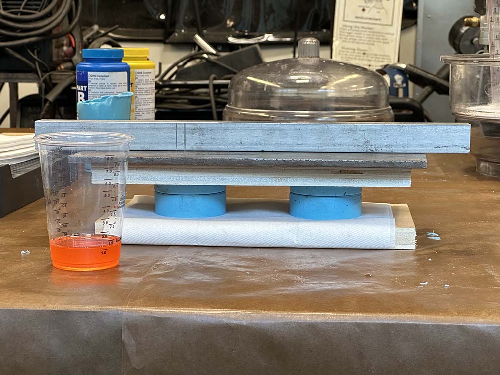
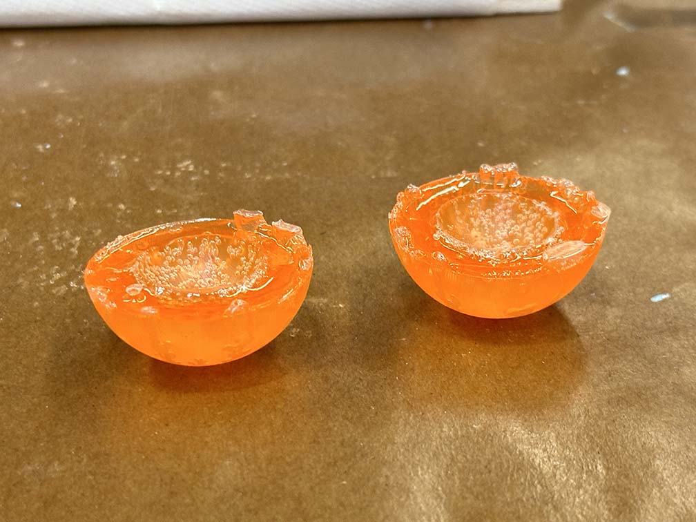
This cast failed. There is a clear under extrusion which is a result of guestimating the expansion of the plastic. The previous attempt bubbled quite a bit and as a result expanded quite a bit. To avoid overflowing the mold I underfilled it. This was a bit too much I guess. Time to do it again! Below is the ~next~ casting attempt with just a few extra mills of plastic. The results are shown below.
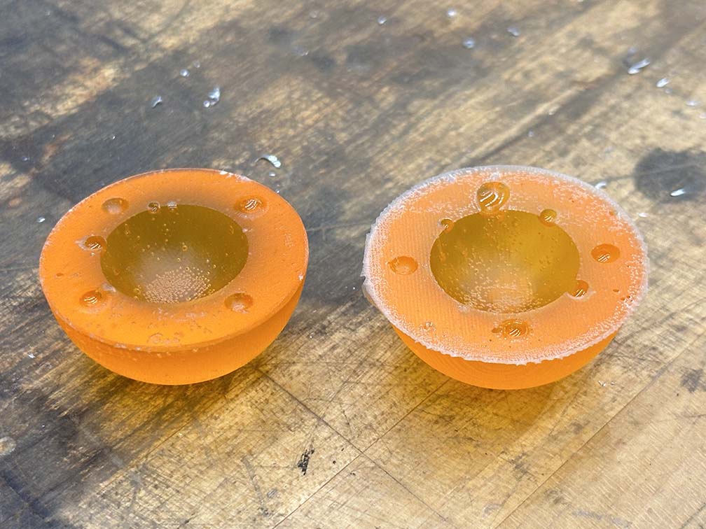
I'd say that's a winner! It's not perfect, but it has a smooth finish and is more or less the part I want. There is a slight lip around the parts, but this is to be expected. A little bit of razor blade cutting and fine grit sanding removes the lip with ease. In the figure above, the processed part is on the left and the unprocessed part is on the right. I really do like the bubble effect here, it almost looks like sun spots to me (or maybe I just want them to look like sunspots, but so be it).
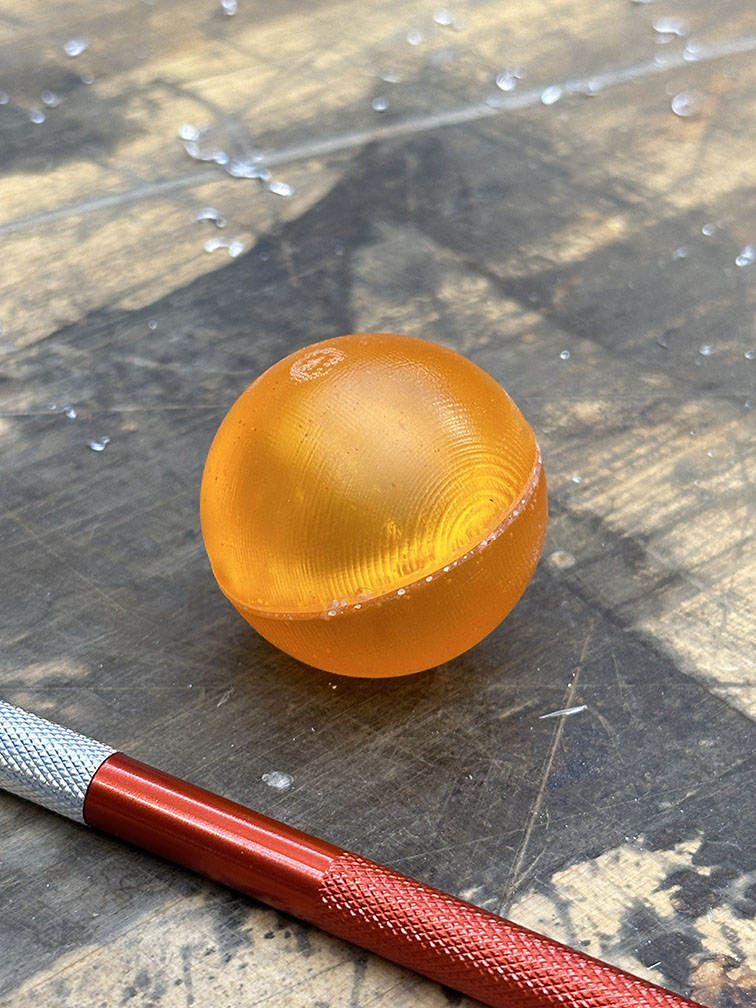
This meets the requirements for the week, but we are not done yet. This is cool and all, but I wanted the power of the sun in the palm of my hand, and this is not very powerful or sunlike at the moment. The sphere is hollow, so let's fill it with light. To do this I need to create a simple circuit. Following the same process as last week, I made a simple board for a LED and a resistor. The very simplified process is shown below (let it be known these three pictures represent several hours of suffering with the soldering iron and trial and error to get the sizing right and several board designs).
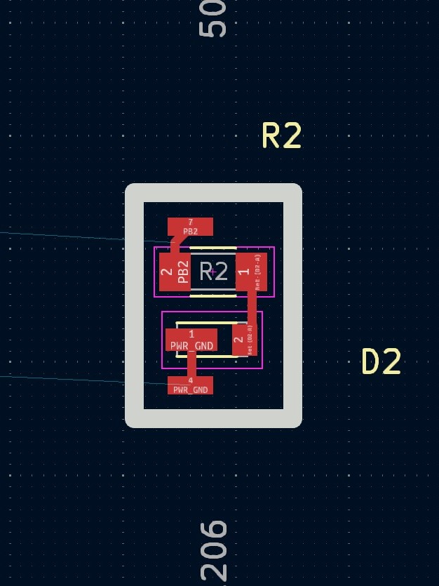
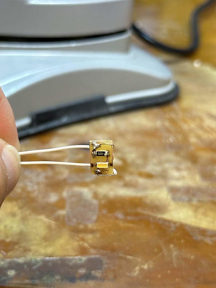
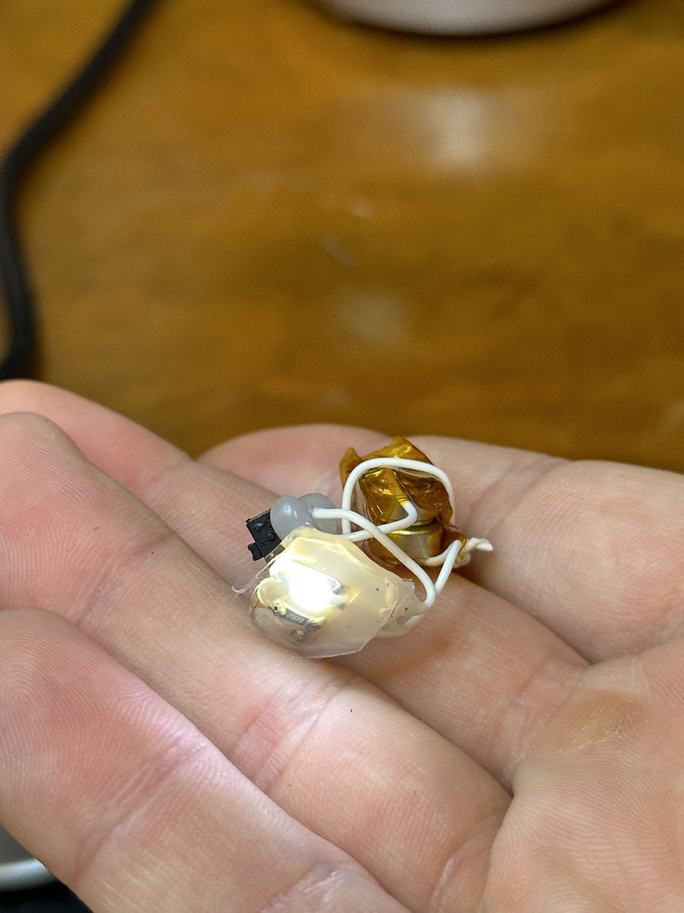
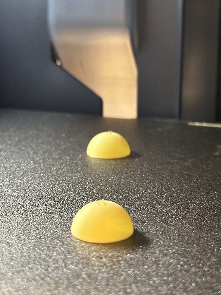
With this little circuit made, we just need to hook it up to a switch and some batteries and stick it inside the o r b (again that sentece cause many a hour to be lost this past week). The final light circuit is shown below. One thing that bugs me is that the light is very sharp through the plastic, and I would like it to be more diffuse. This is simple enough to achieve - pulling from the 3D printing week, we can print a few hemispheres of diameter equal to the inner orb diameter using the 3D printer's "spiral vase" mode to create a thin shell of plastic. I did this on the bamboo and found some matte PLA which ended up looking rediculously nice for some reason. That is also shown below. Putting the two together and we get what looks like the a middle school diagram of the sun complete with a core!
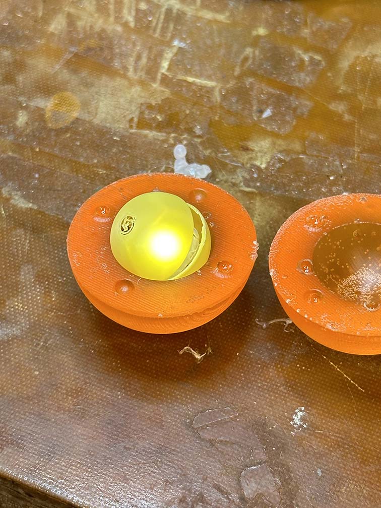

I'm a big fan. Time to put it together and do a well deserved photoshoot. The files for this one are below, but otherwise, ~enjoy~
The power of the sun, in the palm of my hand.
