The TheriColor Digital Theremin
Video
Introduction & Concept Development
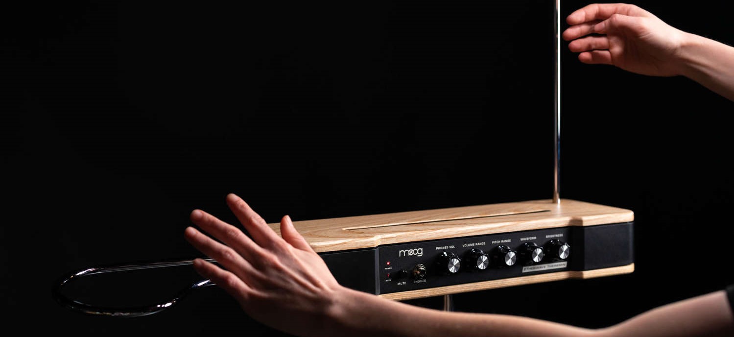
Invented inn 1928 by Leon Theremin, the Theremin is a unique musical instrument controlled by a musician entirely free of contact to the device. The sound of the Theremin is distinct, and found throughout pop culture and music, such as the theme for Star Trek and the Beach Boys hit Good Vibrations. This unique musical instrument is an ideal candidate for a feasible final project for this course as it maps input devices to output devices, makes use of multiple types of manufacturing, and is artistic both in functionality and in form.
The concept of a making a digital Theremin is straightforward. Below is a concept sketch that outlines the basic functionality of a Theremin as percieved by the musician playing it. The vertical antenna controls pitch of the waveform and the horizontal coil controls volume.The step response between the players hands and the coil varies the pitch and volume of the Theremin.
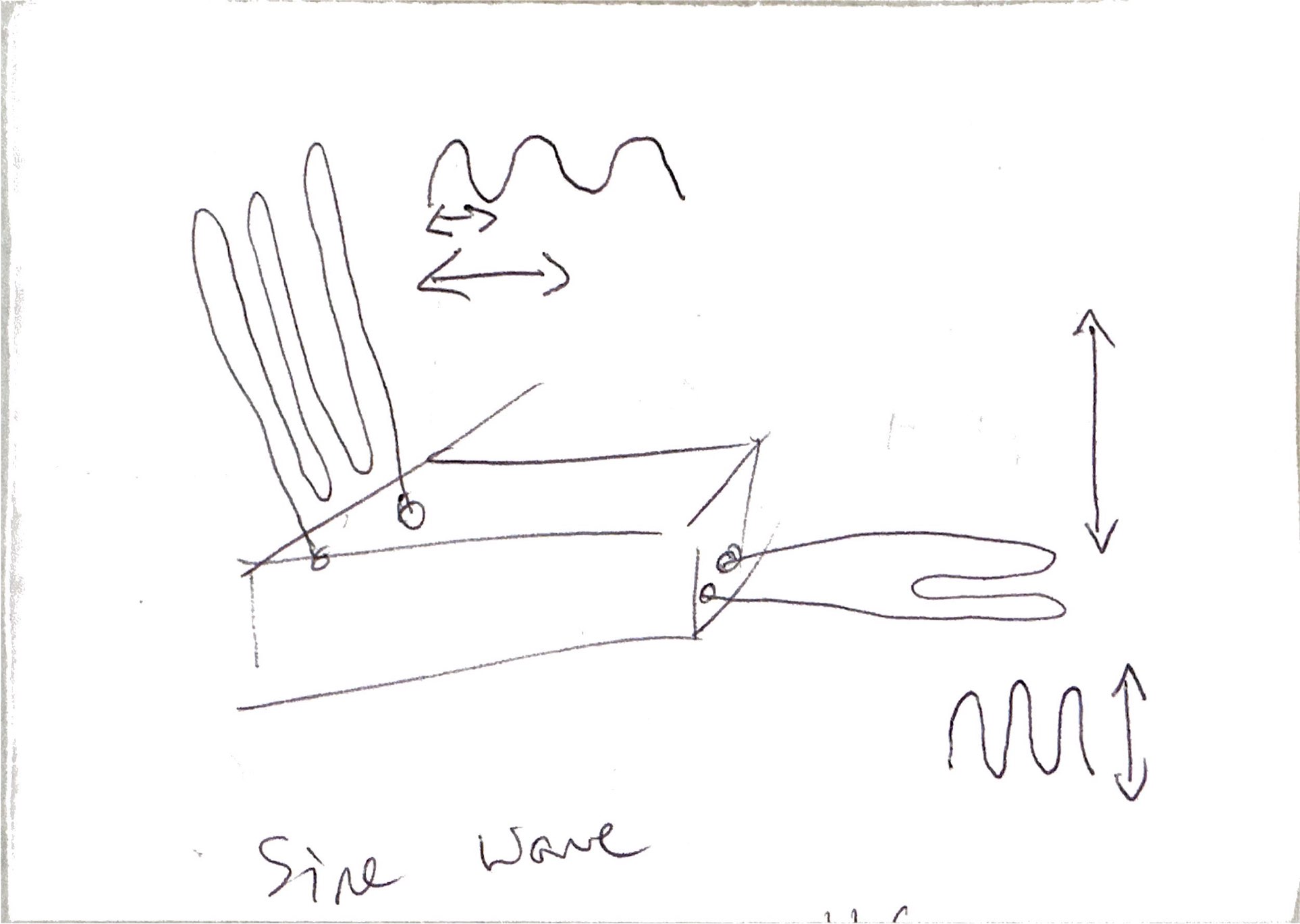
Converting this concept into a physical form, detailed subsections exist below to track the development of this project and outline how you could also build your own digital Theremin.
Concept CAD
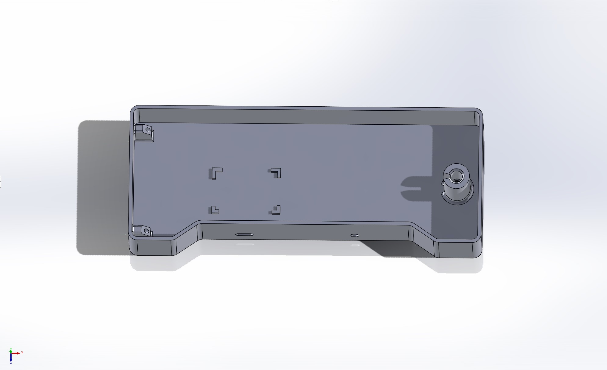
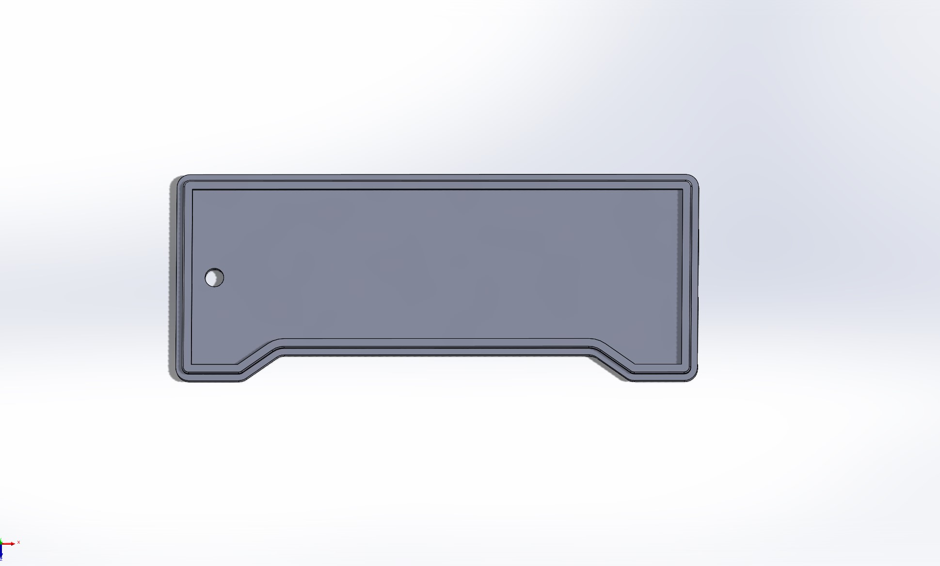
The main component for a Theremin is the physical housing of the antennas and electronics. The spacing and geometry of the step response conductors is critical in determining the relative ranges for the instrument. Here the form and function of the device are equally dependent on one another. The initial concept CAD for a simple box is shown that connects a vertical antenna and horizontal coil to a simple chipset.
System Development
The concept for the Theremin at the system level is shown below. Here we have multiple user inputs that will vary an I2S audio signal output. An additional output that I think would be interesting is a networked set of LEDs that could change color in response to the volume and pitch of the instrument as commanded by the player. The networked output is included in the system diagram below.
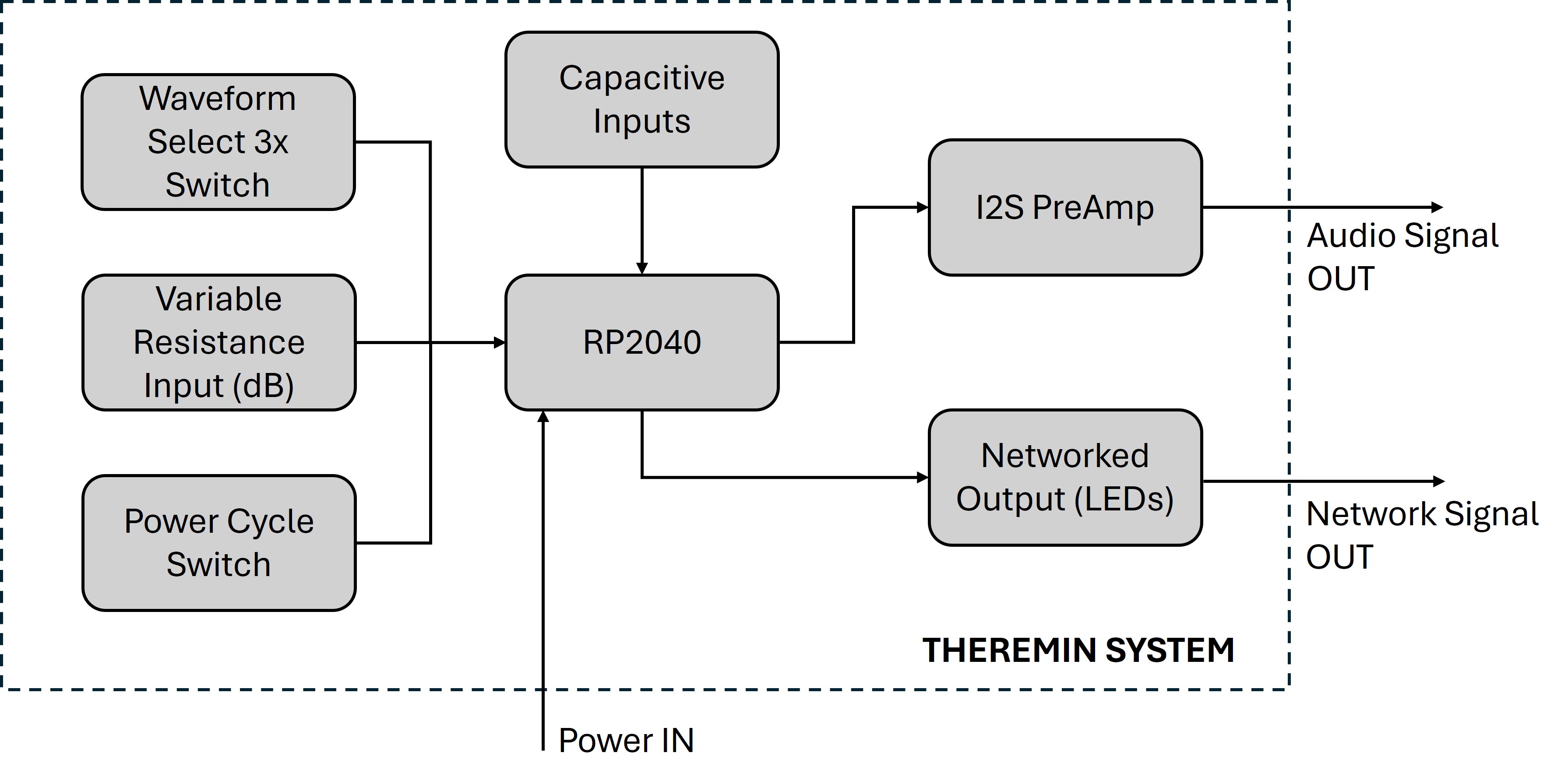
Here there are four main user inputs. The three on the left side are user defined presets for the audio synthesis. A power cycle switch (on/off), variable resistance switch (gain/volume preset), and a waveform select (3-way switch to choose between genuine Theremin heterodyne sine wave sound, square wave, or sawtooth wave) sets the mode of output audio. The other user input is the actual hand controls that adjust the step response measurement for the microcontroller. In this system, a microcontroller (identified here as the RP2040), will synthesize these inputs into a I2S waveform output that will then be sent to a COTS I2S preamp chip before being sent as an audio signal output, either as a 0.25" audio jack or as a connection for powered loudspeakers. In addition to the classic Theremin functionality, the networked communications for remote RGB LED light control is shown. This would be fun and add an additional dimension of expression for the music and the musician, as well as enable hard of hearing individuals to enjoy the Theremin. Below is the systems diagram for the networked lights.

Project Tasks and Schedule
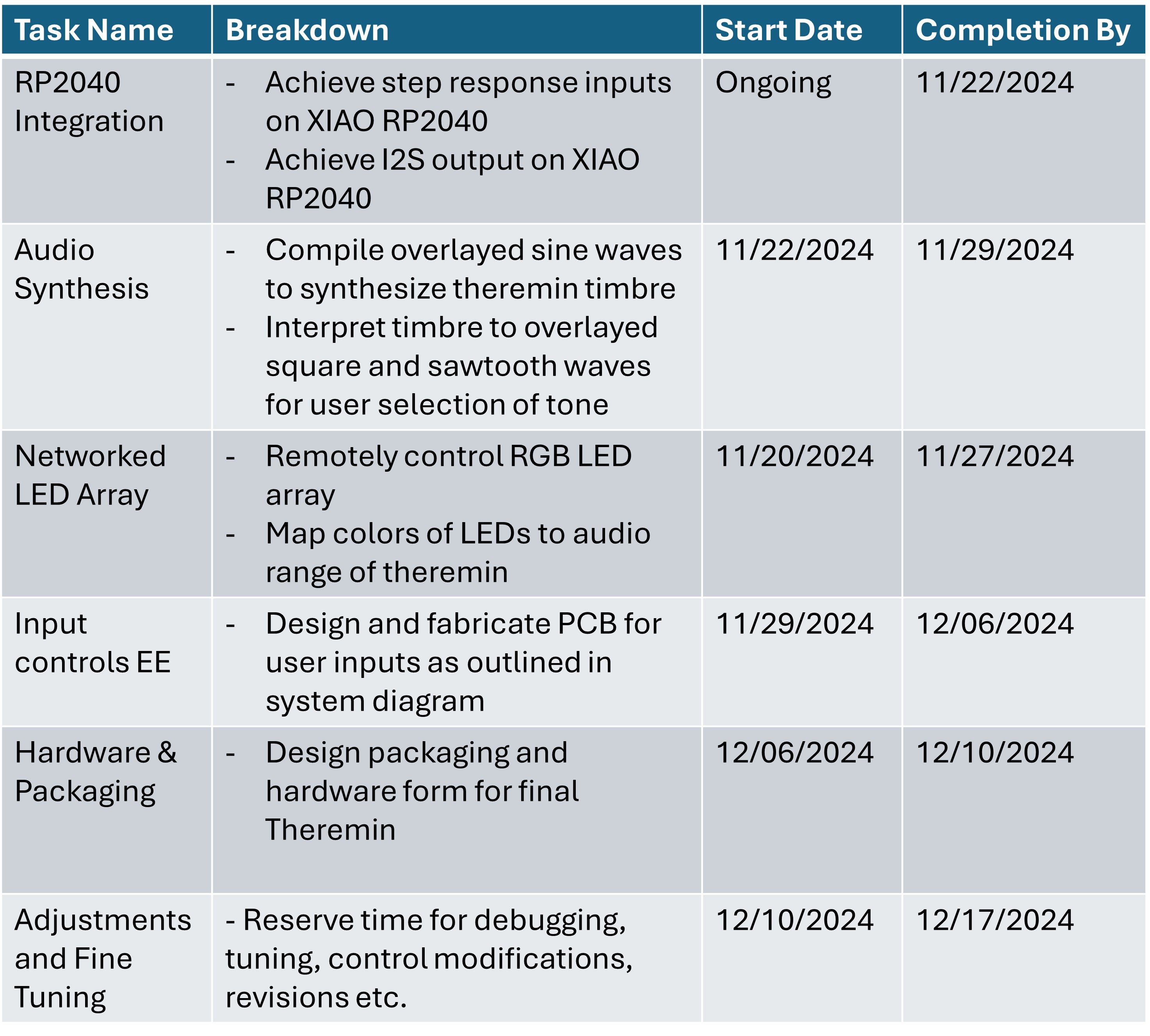
Below is a table that outlines the general high level tasks to be completed to successfuly make this project. The breakdown identifies subtasks and the dates provide a timeline to achieve my goals within the course schedule. Largely there are 5 main tasks: I2S software integration with the RP2040 microcontroller, software audio synthesis, networking and communications for the LED array, input devices and embedded electronics for the user presets, and packaging / hardware design. At the end of the project, I leave a week dedicated to debugging and fine tune adjustments. This task breakdown enables me to achieve the functionality I want to implement while leaving enough room to be creative with my designs as this project is equal parts form and function.
Inputs and Outputs: Two-Week Theremin demo
For the inputs week and outputs week, I decided to make a Theremin. This sprint is what got me on the track for switching my final project to building a Theremin, and below are links to those pages for the full breakdown. The highlights are also below.
Inputs Week: Step Response Measurements
Here I measured the step response signals from the native QTouch pins on a SAMD21 microcontroller. These signals came from two copper pads which later I would map to be the Theremin sound outputs.
This week was a more hectic push where I printed the CAD box and assembled a function, although quirky, Theremin complete with an AUX output to my portable speaker. Here is a lovely video of Neil playing that theremin.
Detailed CAD
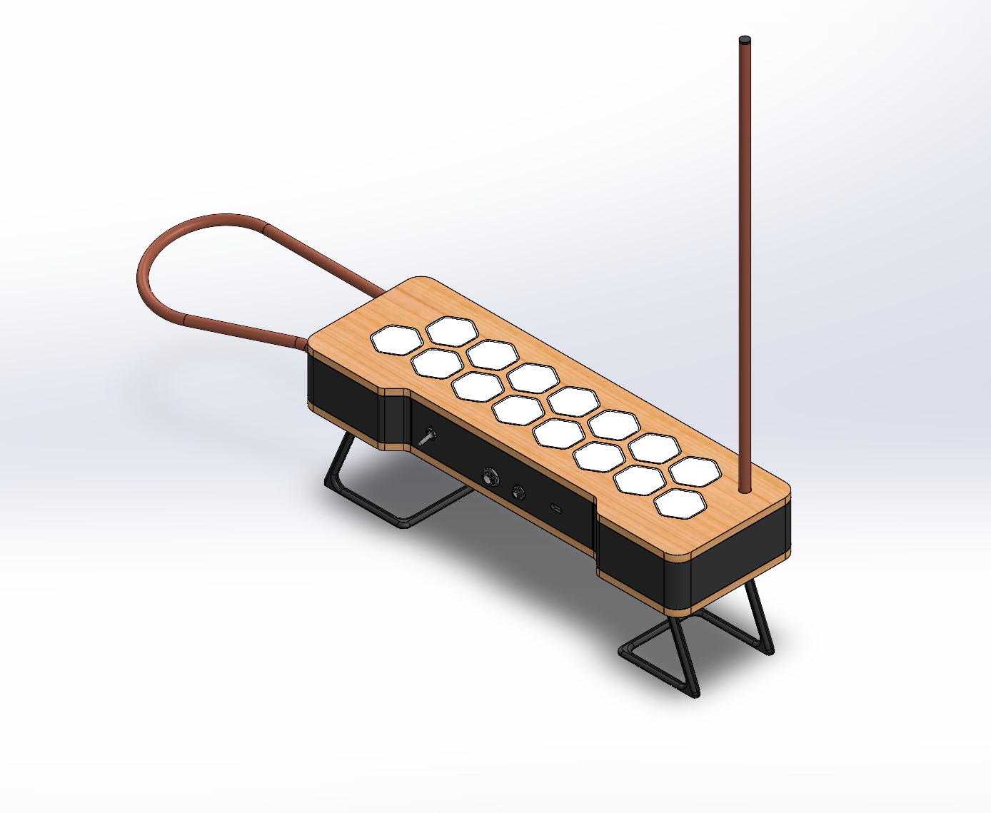
With a working prototype and well defined system boundary, the next step is to make progress across the PCB design and physical design of the theremin. Here we will discuss the physical design. I want to keep the design similar to the prototype, such that it remains a reference to the Moog Etherwave theremin, but lean more into the mid-century modern aesthetic. Aesthetics aside, the main interface to be aware of is the PCB to housing interface. The electrical and physical connections will need to be varied as crunch time hits and the scope rapidly shrinks. Building in flexibility to the design upfront is a best-practice thing and helps make last-minute changes a bit less painful.
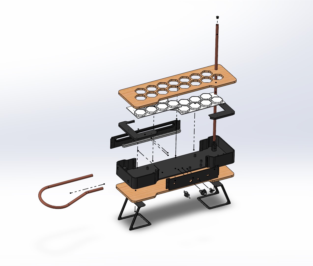
Here I have the physical interface for my PCB as set screws of 1/16" diameter. The base housing, a 3D printed object, will have small cylinders that the screws tap into. Also, the networked ESP sits on a dedicated pad to the right of the main board. This board can be connected via a ribbon that communicates using SPI. Next, for the electrical connections, I have a removable back plate that houses the switches and ports for audio and power/data connections. If the configuration of the ports needs to be adjusted, then a new backplate can be printed and installed with relative ease.


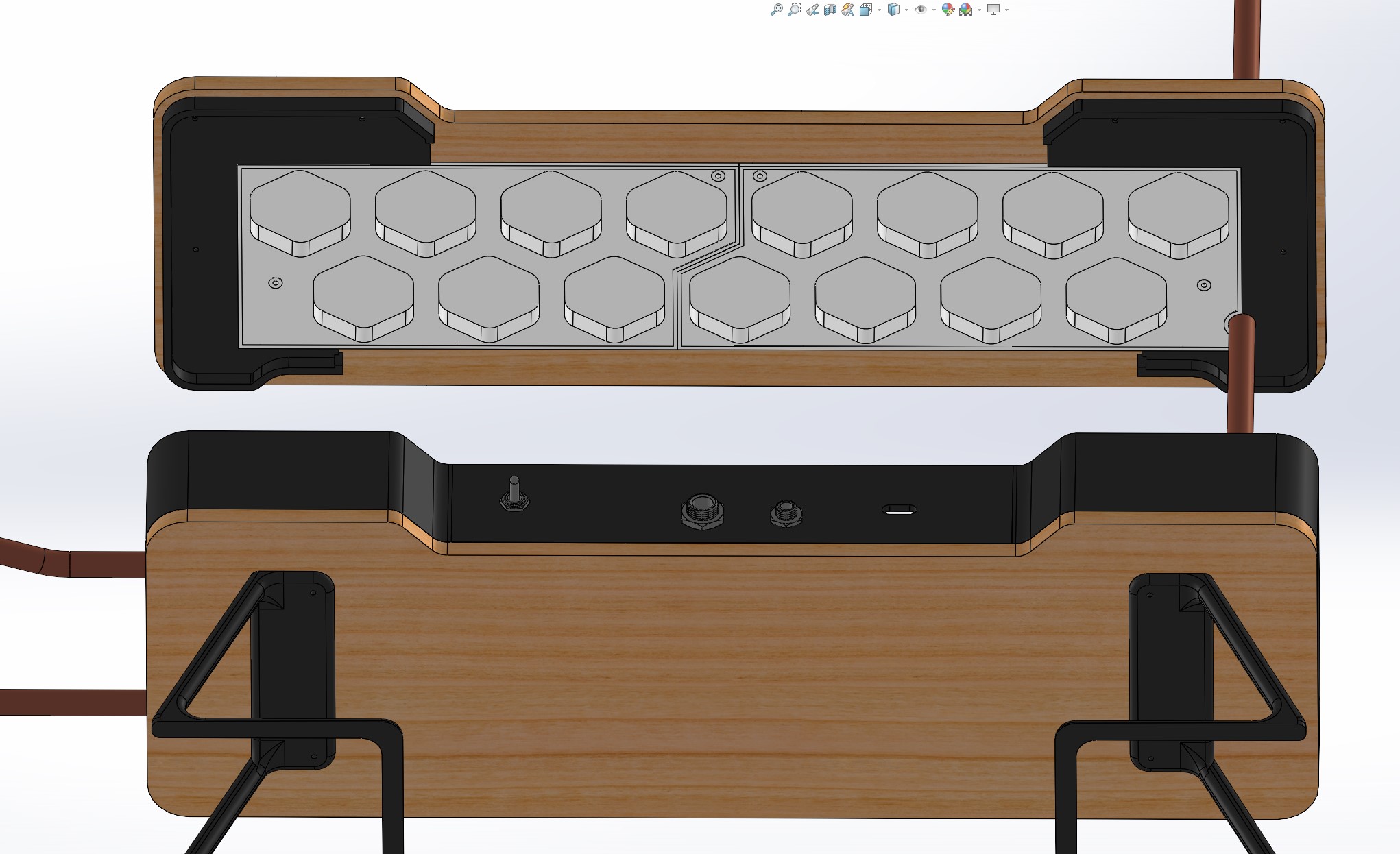
From the final project guidelines, we need to incorporate both additive and subtractive manufacturing in our fabrication process (i.e. not all 3D printed, and noting that milling a PCB does not count as subtractive here, integrated microcontrollers is it's own requirement). To address this, I'll add top and bottom wood panels, like the Etherwave, and I'll mill those out on the shopbot using the leftover stock from the "make something big" week. For the top panel, I want light from the NeoPixels to shine through. The idea here is that the theremin will glow as it plays music in addition to sending out the networked NeoPixel commands. Because I'm a sucker for space-related aesthetics, let's make some hexagonal cutouts. Both as a requirement of the tool diameter in the shopbot and because the vibe of this piece is rounded edges, I'm going to round the edges of the hexagons. Not that this is a particularly important detail, but I think it makes the design more consistent. Below is the top panel for the theremin with rounded cutouts to let colors shine through from the electronics within.

Note that there are registration holes seen here. This figure is from the bottom up (as if we are inside the theremin looking out at the world). These holes are important for aligning the lid and base and to ensure that the lid doesnt slide around. These holes will align the brackets that will fit flush against the inner wall of the base, and those brackets will further be aligned by the hexagonal pads to fill the cutouts in the wood top. These three components comprise the top assembly of the theremin, shown below. Note the clever seam hiding for the 3D print size requrements (I am proud of my ability to conceal things in my designs).
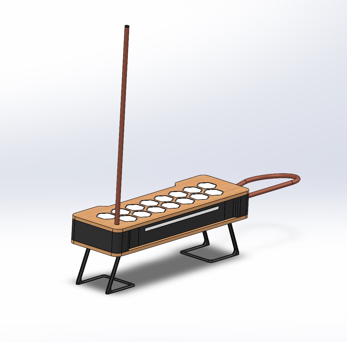
I decided to also add a cutout on the front panel for more color because why not. This panel is also removable, both because I needed to incorporate a seam somewhere for the 3D printing aspect and also because if I want to change the aesthetic of the lightbar upfront then I can later on in the workflow. A simple slot will do for the front panel lightbar. Below is the front panel, again with a thin, white, diffuse layer of PLA to show light but not the rest of the electronics inside.
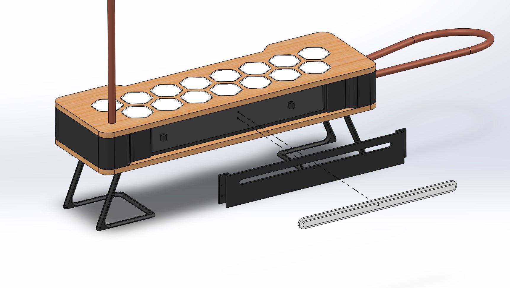
Finally, I want to add feet to this thing, because who doesn't like feet. It felt odd playing the prototype as it sat on the table, so having it elevated a little will both be a good aesthetic and help the player engage with the volume loop. I wated to emulate the look of a continuous piece of bent wire for the stand, so I made a quick design and printed it off. This, while modeling the loop/antenna so I could cut and bend the copper tubing to specified dimensions, completes the detailed design! Below is the final assembly. Note that in this design there is one switch for power cycling, a 1/4" audio jack, 3.5mm audio jack, and USB-C interface for data and power to the theremin. Scope related changes will be covered later on this page.
Additive Manufacturing
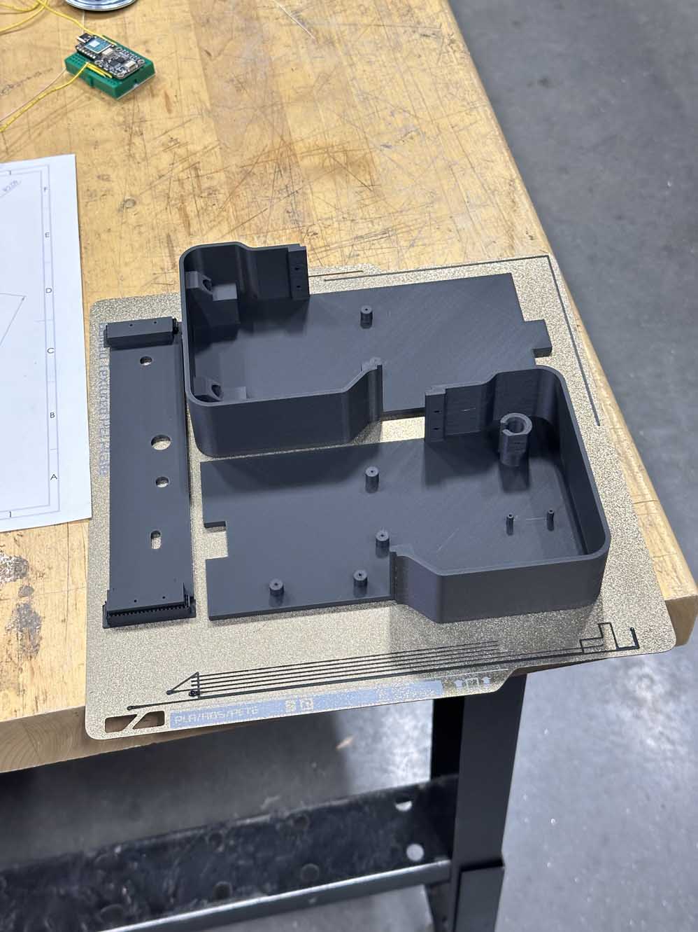
In the above CAD, all of the black and white parts are intended to be 3D printed. I really like how the overture matte black PLA turns out when used in the Bambu FDM printers. These steps were fairly straightforward: I loaded the parts as STEP files into the Bambu studio slicer software and set my layer height to 0.12mm as I was looking for a high quality finish. I think this turned out really well, and in several of the parts it's insane how challenging it is to pick out the layer lines - very well hidden in the process. Below is the first batch of prints. Note that the main body of the Theremin needed to be broken into two parts. These halves will be screwed into place on the base wood panel, but I wanted to ensure they only had one possible alignment (no slippage) so I used a key/slot design to register them. In addition to being useful for part registration, this design decision intentionally offloads the stress from the PCB screws such that the load from any shock the instrument experiences is carried around the outside of the shell and not through the PCB. The seams here are also hidden by the front and back panels. Once again I pride myslef on these little design details. I think they really help the design look intentional and sleek.
Subtractive Manufacturing
The top and bottom wood panels are made using subractive manufacturing. Here I used the shopbot to cut away at the leftover stock I had from furniture week. Since that stock was 0.5" and I needed 0.25" for my panels, I needed to first plane away the top half of the board. After that the fusion toolpath demo as seen in CNC make something big week is exactly the process I used here. Below is that toolpath.
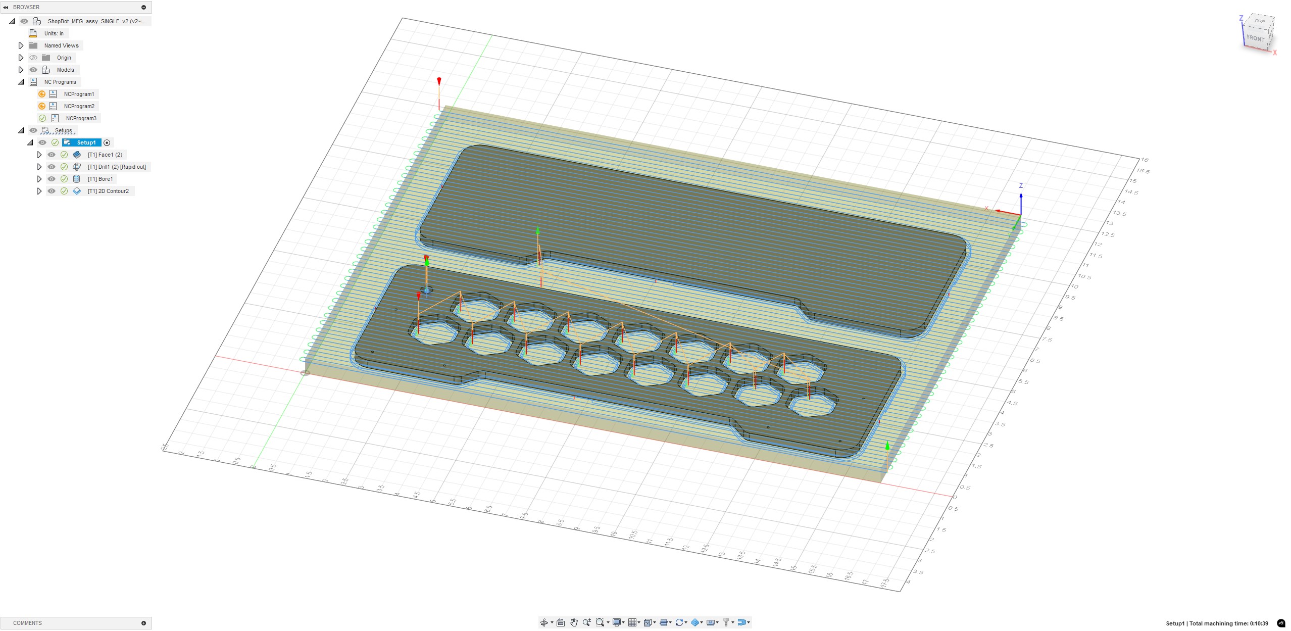
And, for your viewing pleasure, here is a timelapse of the parts being made on the shopbot.
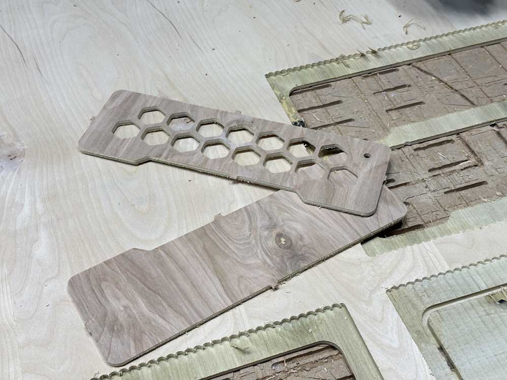
The wood panels that turned out best are shown above. I had to mill a few times because the face plane operation kept producing sloping parts that really annoyed me. These are primarily for aesthetic, so the look is key. I did a bunch of debugging, and eventually took a level to the ShopBot - turns out the gantry arm is ever so slightly tilted from the plane (~0.5deg) but this is enough to cause noticeable height differences in my planing operation. Eventually, and after much troubleshooting, Alfonso found some 1/4" stock he had in the CBA lab and helped me crank out a couple of pristine wood panels using the Zund. This was super cool to see and I wish I had more time to learn about that machine since it is so versatile.
System Scope Changes and Challenges
One of the things Neil repeatedly said during the year is that the scope of our projects would seem to rapidly collapse as we played triage on getting them done by the deadline. Despite my best efforts to avoid this, it was inevitable. Due to time and throughput constraints, I needed to abandon the networked lights. Nice in theory, but aux to the rest of the theremin. Additionally, The idea to have gain controls and such on the back panel needed to be descoped since that was again a nice to have but not a need to have. Lastly, and this is the biggest change, I needed to abandon my attempts of I2S on the RP2040. The idea of this was great, and I would love to redesign the electronics of my completed theremin with this architecture, but I needed to focus on improving the prototype I already had, not build a new architecture from the ground up. The main reason for this is that in Neils examples, he uses micropy - a version of python for microcontrollers. This is a super useful skill to have and I want to learn it; however, none of my previous work was in micropy so I needed to keep things in C since that was what I was most comfortable working in. A future version of this project should really make use of the RP2040 as it is much better suited for this application.
Embedded Microcontroller and PCB Development
From the scope shrink and triage efforts above, the PCB and it's components needed to change rather dramatically. The RP2040 is replaced with a SAMD21 and the I2S breakout board is axed. Thankfully, the XIAO RP2040 and SAMD21 have the same footprint and pad structure. To reduce power consumption on my computer USB port, I'll opt for 4 NeoPixels on the main board. The other reduction is the complete elimination of the networked ESP32 and other wifi-networked NeoPixel boards. This leaves an empty spot in the base of the theremin for another board, or for the option to expand later on, but for now the design will be a single XIAO SAMD21 and DAC hookups for the audio out signals.
For the design of it, I wanted to have the power switch actually cycle the system power (as one would probably expect from a power switch). To accomplish this, I (rather heinously) added a USB-C breakout chip at the edge of the board for the interface to the outside world, and a direct trace to another USB-C breakout with the ground going to the power cycling switch. (EDITORS NOTE FROM THE FUTURE: DO NOT INTERRUPT THE GROUND, INTERRUPT THE BUS VOLTAGE). The breakout chip is then wired with a short cable to the XIAO. The reason I did this extra work instead of opting for the simpler USB-C power breakout chip and using V-IN on the XIAO is because the NeoPixels require 5V and the XIAO only supplies 5V directly from the USB VBUS. While I could do more for power handling and directing power using an H-bridge or similar, as we learned about in outputs week, this was a triage decision. A future iteration of this board would certainly include a more robust power handling system. For now, this quick and dirty workaround meets all my current goals for the project, so we're rolling with it. I also added screw terminals for the antennas, audio jacks, and power switch hookups. Below is the schematic and traces for the PCB, done in KiCad.

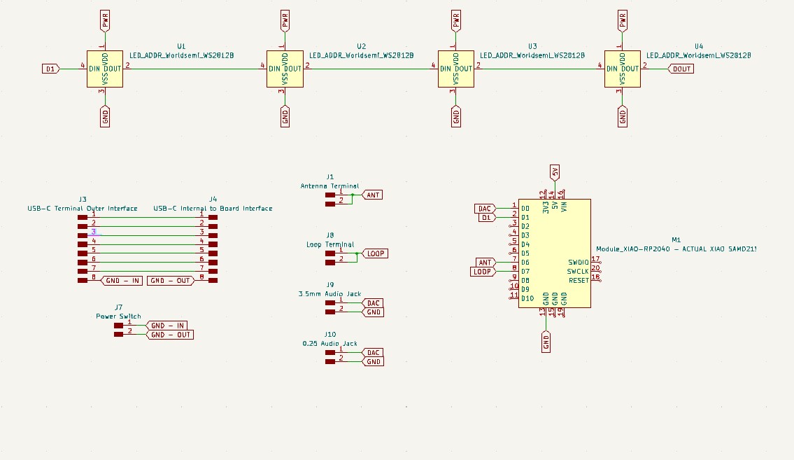
EDITORS NOTE FROM THE FUTURE: can you spot the mistake in the above schematic? Answer revealed below!
The board was milled on the Carvera a few times. The first time I realized that my placement for the second USB-C breakout was just slightly too far for the short cable I got for this project. As a result, I adjusted the position of the second breakout board to be at a 90deg offset. I milled the board again and realized that the 1/32" bit needed to be replaced, so, I replaced the bit and milled yet again. Third times the charm. Below is the final milled board.
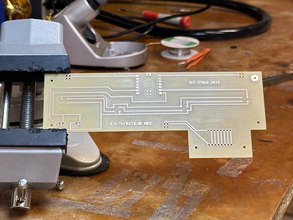
As I began soldering I noticed two mistakes that I didn't catch in the above schematic: (1) the second USB-C is mirrored to the first, this means that it either needs to be placed on the bottom of the board or upside down (thankfully the short cable I got works for under the board as well as on top of it), and (2) I forgot to re-label the power input for the neopixels after my last PCB redesign. Initially I had the power switch cycling the voltage supplied to the I2S chip and the NeoPixels, but after that redesign I changed my power labels and forgot to update the NeoPixel power input. Time for a jumper wire. While I could solve both of these problems by fixing my schematic and remilling the board, we are in triage mode now and working with a very fast ticking clock, so this will have to do. Looking back at the board, these mistakes are obvious, but oh well, such is the way of prototyping. After a quick learning curve of surface mount soldering (and a few burns from the heat gun to remove some accidents), the final PCB is complete and shown below.
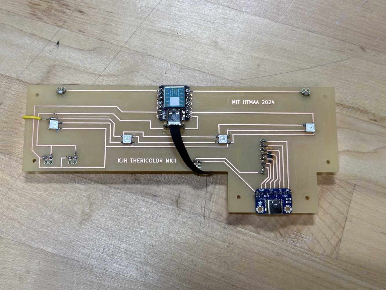
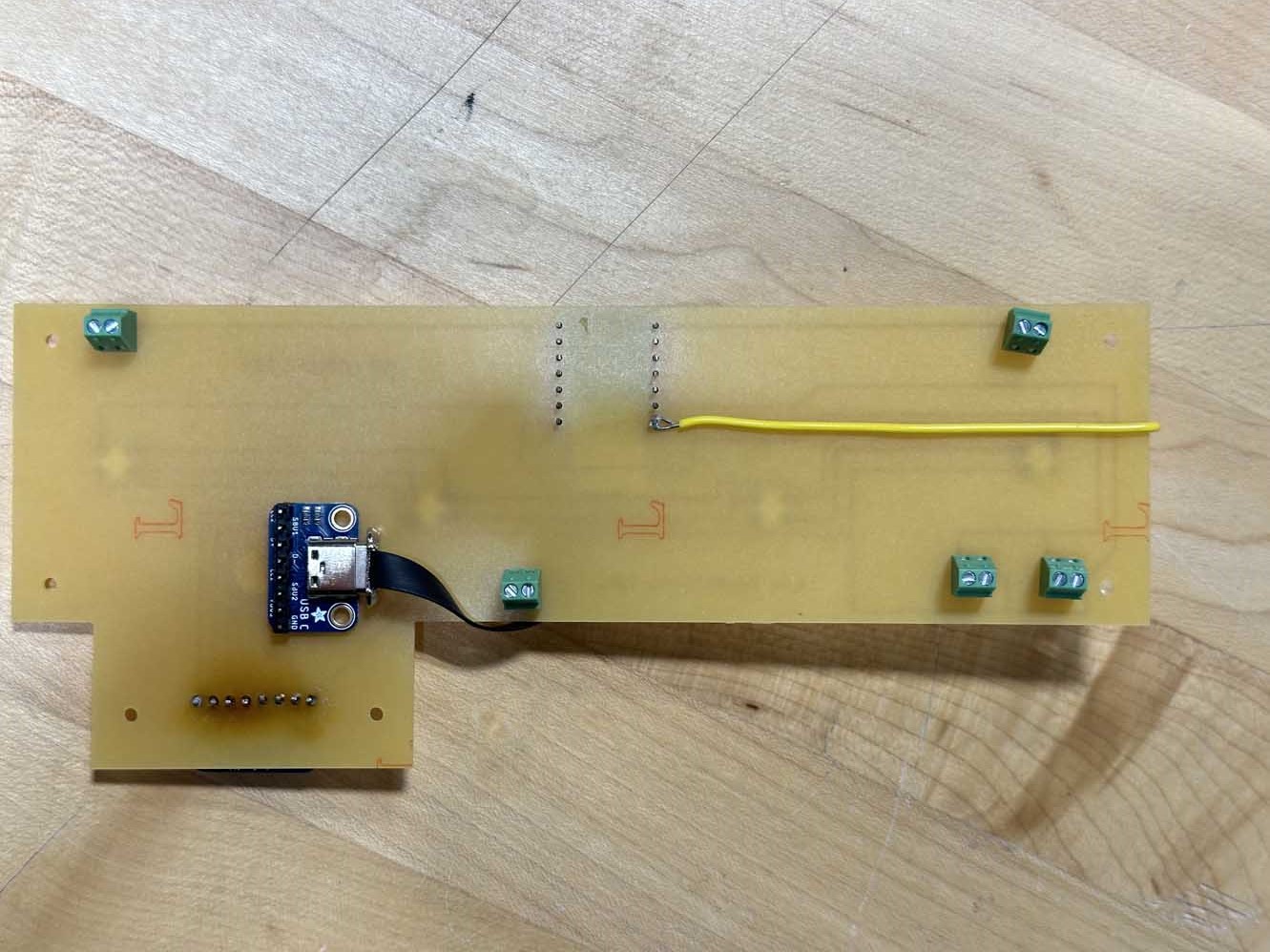
And again, here is a fun time lapse of the soldering.
KiCAD Files (you need all of them to make it work)
- Download KiCad PCB File
- Download KiCad Library File
- Download KiCad Project File
- Download KiCad Schematic File
Software
Software for an updated version of the theremin was a tricky problem. Initially, I was going to have a mathematically generated sine wave that was delivered over I2S to a breakout preamp chip and then finally at line-level to some loudspeakers. This got reworked in the scope shrink (noted above), but I still wanted to fix a few key issues in the original code. First was the tone. The original tone was a square wave, which, and pardon my french, was quite simply fucking awful to listen to. Neat demo but like glass on the ears. This was my main priority. Next on the list was granularity. The original sound jumped around in descrete steps that were audible and actually larger than half note scale tones, so learning the jumps didn't help with trying to play the instrument. Resolving the granularity into a smooth flow of sound was next. Finally, I wanted to linearize the sound. The capacitive step response is exponential in nature, and because of this the tone is sluggish to change at ~8in from the antenna and quickly changes when the player is ~1in from the antenna. Having a linear distribution of sound will drastically increase the playability of the theremin. An additional note on software is that I want to add NeoPixels to follow the sound (brightness for volume and color for pitch), but this is relatively straightforward so I'll leave it for the end (EDITORS NOTE FROM THE FUTURE: THIS WAS, IN FACT, NOT STRAIGHTFORWARD. Bonus points if you know why, and I'll give you a hint, it's about interrupts). Let's jump in.
The original code I used was based on Quentin's touch piano (more about that in outputs week), so the tone is generated by making use of interrupts in the clock and modulating the voltage high or low (at the classic 255 resolution). To change the tone, I sampled some theremin music online and isolated a signle period of the adjusted sine wave for a theremin playing roughly an A4 concert tone. This seemed like a good place to start for modulating it up and down and not getting too distorted. I converted the sine wave .wav file into a .h header file and imported that into my project folder in the Arduino IDE. From there I got the code to play the tone on loop, and it sounded pretty good! Quentin mentioned that to distort the sound I could skip samples in the sine wave (higher pitch) and double samples in the wave (lower pitch), this seemed good in theory, but I didn't have a clear idea of how to accomplish this and the risk of loosing audio quality on the higher pitches when too many samples are skipped was almost certain since my sine wave was only 120 samples in length. This process also seemed computationally intensive and I feared the response of the theremin would lag if I asked my poor little SAMD to do too much math while executing it's other tasks (this was a hunch and based on nothing but my own intuition). The much more crude way of modulating the pitch I learned was to adjust the clock frequency of the interrupt. This seems like the equivalent of dimming the lights in your house by decreasing the number of active generators at your local power plant, but hey if it fits it ships, and this certainly changed the tone. After a little bit of clever programming of getting the clock to abandon it's interrupt routine and take on a new one with every cycle of the loop when the step response values updated, the code worked! While I would love to take credit for this accomplishment, the real heavy lifting here was Quentin and an outside party who took a vested interest in this problem (big ol' shout out to Elsa - full time rocket scientist and embedded software engineer).
With the first two tasks complete, I moved on to linearization. The idea here is simple, have a discrete set of values for the qtouch input and map those to a discrete set of linear frequency values and interpolate between them. Nothing fancy, but the crucial part of it all is the exponential array of qtouch values. I got a rough version of this concept working, but the array wasn't tuned well enough for the sound to sound soundly. I used putty to map the serial data of the frequency outputs (roughly in range of 7800 to 58000) while moving my hand at a constant velocity towards the antenna. Despite mapping the first array as close as possible to this graph, the sound wasn't quite at par for what I wanted. As a triage decision, this was elected to be sent to backlog in favor of the NeoPixels. If time permits, I'll revisit it.
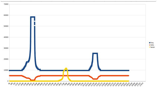
Here's a funny thing about my thought that neopixels would be easy. Apparently the neopixel library overwrites interrupts to do it's own PWM to the LEDs on the tiny integrated chip. This makes NeoPixels a breeze for most people, but this made integrating them a nightmare for my project, since the entirety of my sound was dependent on timing my interrupts. After much head scratching, I had to abandon my desire to have color mapped and updated to sound. This was pretty defeating, BUT I was able to seta constant color to my NeoPixels in the setup of the code and then not update them again, so at least the TheriColor(TM) will live up to it's name somewhat. The hardware exists and is in place to have a nice linearized sound map with corresponding dancing lights, but these will require a bit more software time and at this point I need to prioritize this, the documentation of my work, before the course ends. A future software update will be able to incorporate these features, but until then, below is the completed version of my code, complete with all the above functionality and commented portions that are WIP of the NeoPixel code (note: it is a file download since you also need the audio header file).
CODE
System Integration and Final Project
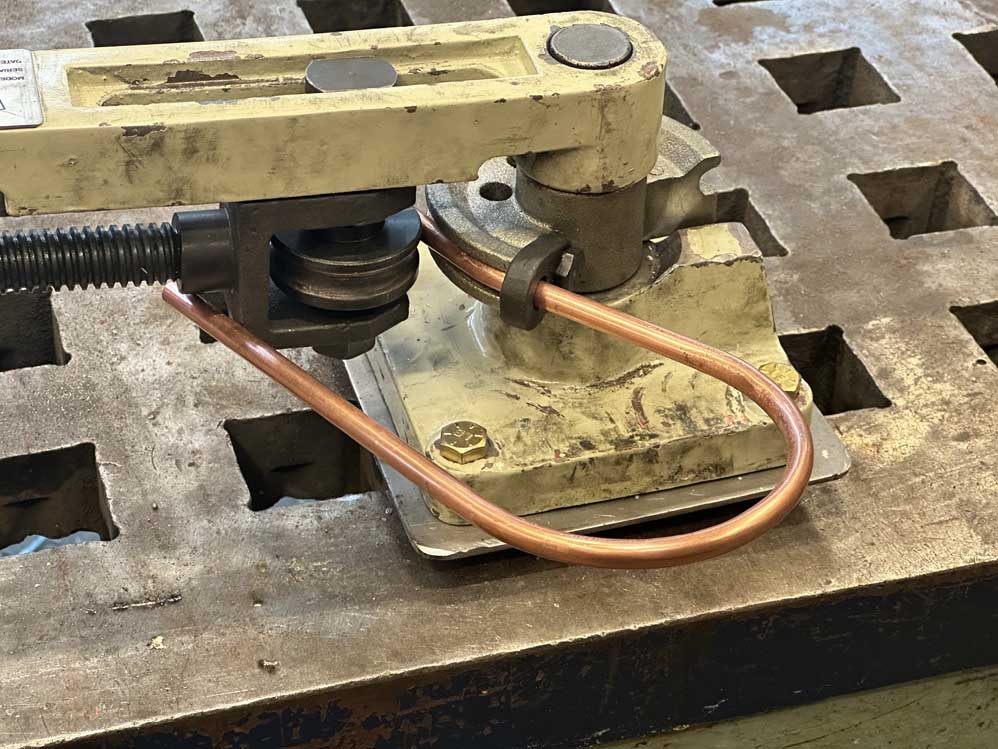
The first step in the final assembly was to make the bent copper loop. This was a lot of fun. I've used a pipe bender before, so I followed along a scale engineering drawing of the loop and bent the copper to shape. Below is that process
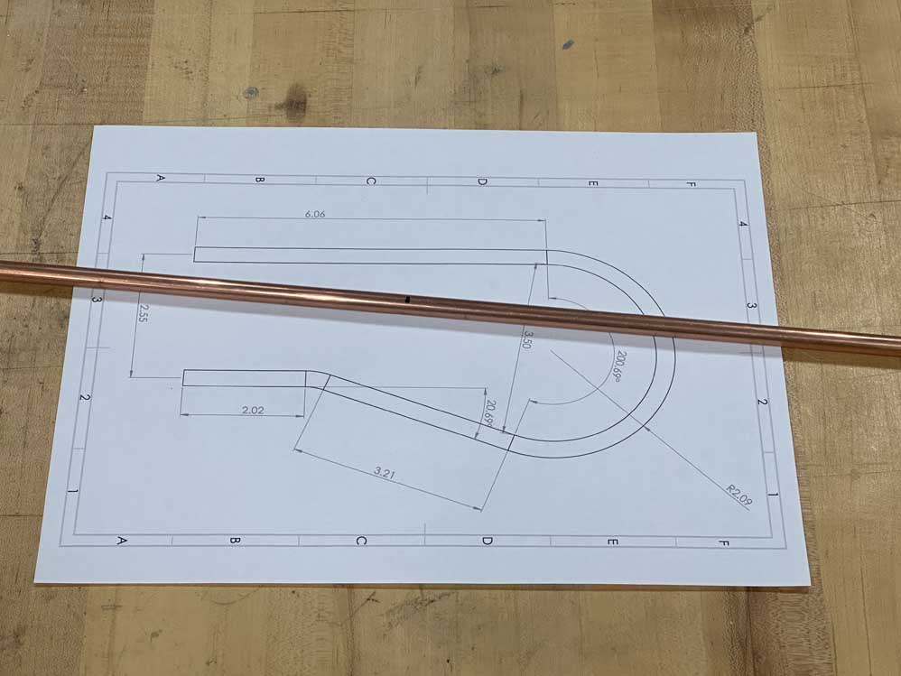
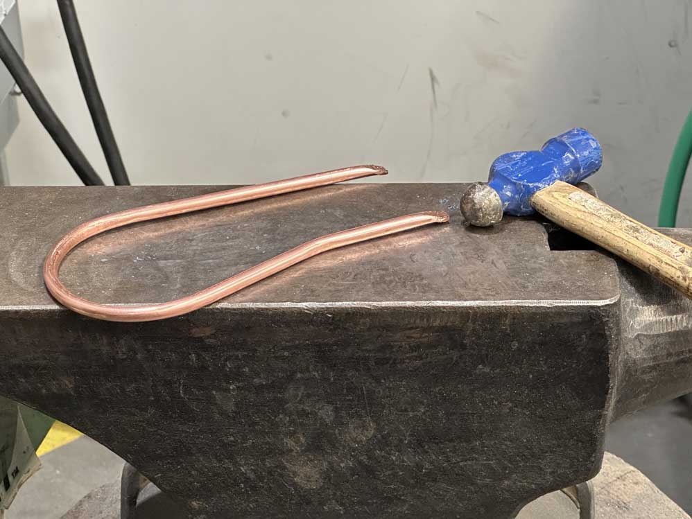
After the tube was bent, I needed to flatten the edges so I could tap the ends for the electrical leads. This was a LOT of fun. I used a hammer and an anvil for this (yes I had a real life use for an anvil and I felt like I was living in D&D it was an incredible rush). Below is a picture of that.
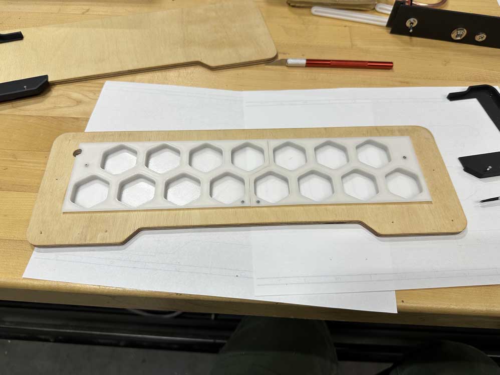
The first part of system integration was the top assembly where the 3D printed parts and CNC milled parts met. This was a test of my design and GD&T skills, but holy cow it worked first try. Below is the process of my glorious part registration rush (yes it was a rush because the high I felt when the hexagons ~perfectly~ snapped into place in the cutouts was next-level).

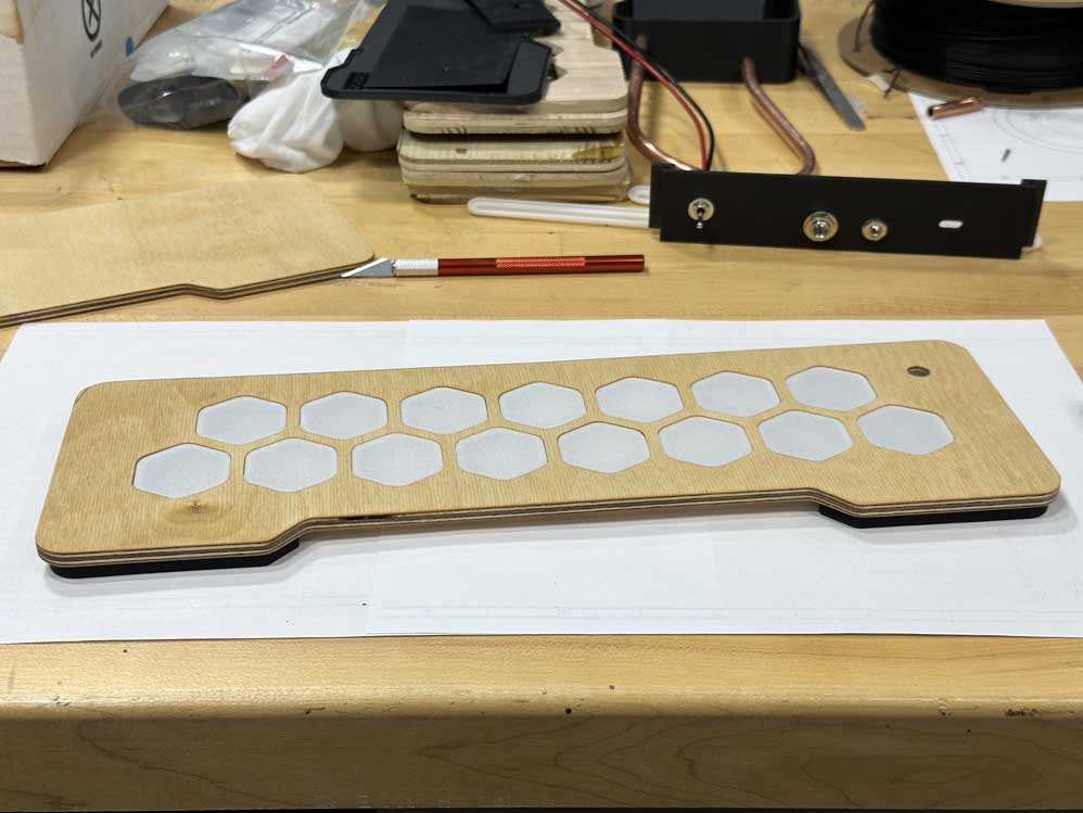
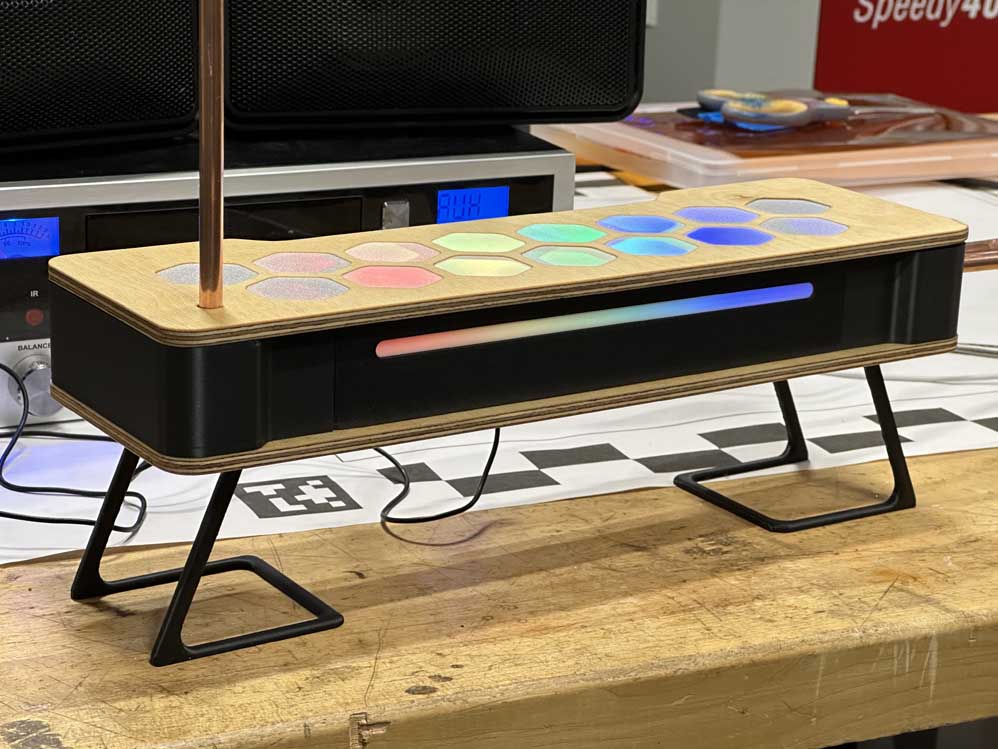
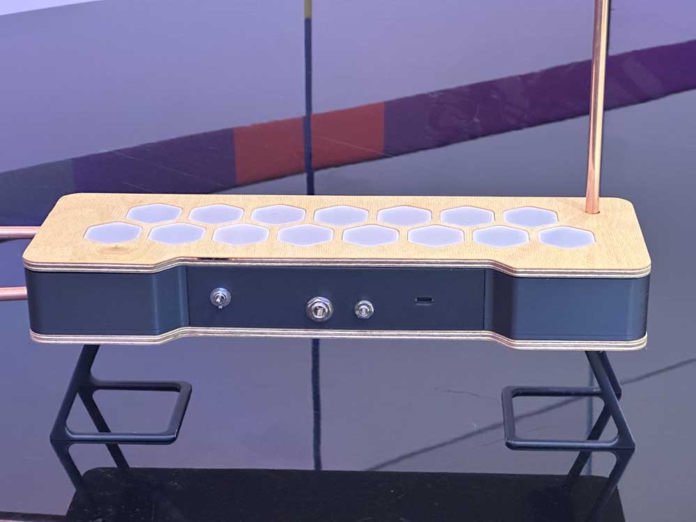
Assembly of the final theremin was a lot of fun. My part registration was spot on and all parts fit like well designed gloves (this is something I know I can do well and I won't shy away from being proud of it). Some trickery was found in trying to get the audio jacks wired up, but such is the way of working in tight spaces. I added some details at the end as well, like the antenna plug cap, just to add some pizzaz. The main integration issues I ran into were the software bugs and the electronics fixes that I noted above. One very interesting thing that caused me much stress, as I alluded to above, is that the power cycle switch, which interrupts the ground of my USB-C breakout, fried one of the breakout chips when I used it. I dont exactly understand why, but I had to replace that chip after the project was integrated, which, quite frankly, sucked. Note to self, and I'll add it above as an editors note from the future, dont interrupt the ground; interrupt the bus voltage. That switch is less of a power cycle switch and more a permanent kill switch. Guess that adds to the vibe. Below is a fun time lapse of me assembling the theremin, and some glory shots in the Media Lab for fun.
After building the thing, the RGB neopixels took a bit of work to spin up, but eventually we got there! first with a solid color, and then with a rainbow diffused through the light panels. The look is perfect. Also, the soldering and connections to the physical housing took a bit of time to finagle. Below are the pictures from the soldering endeavors followed by the neopixels.
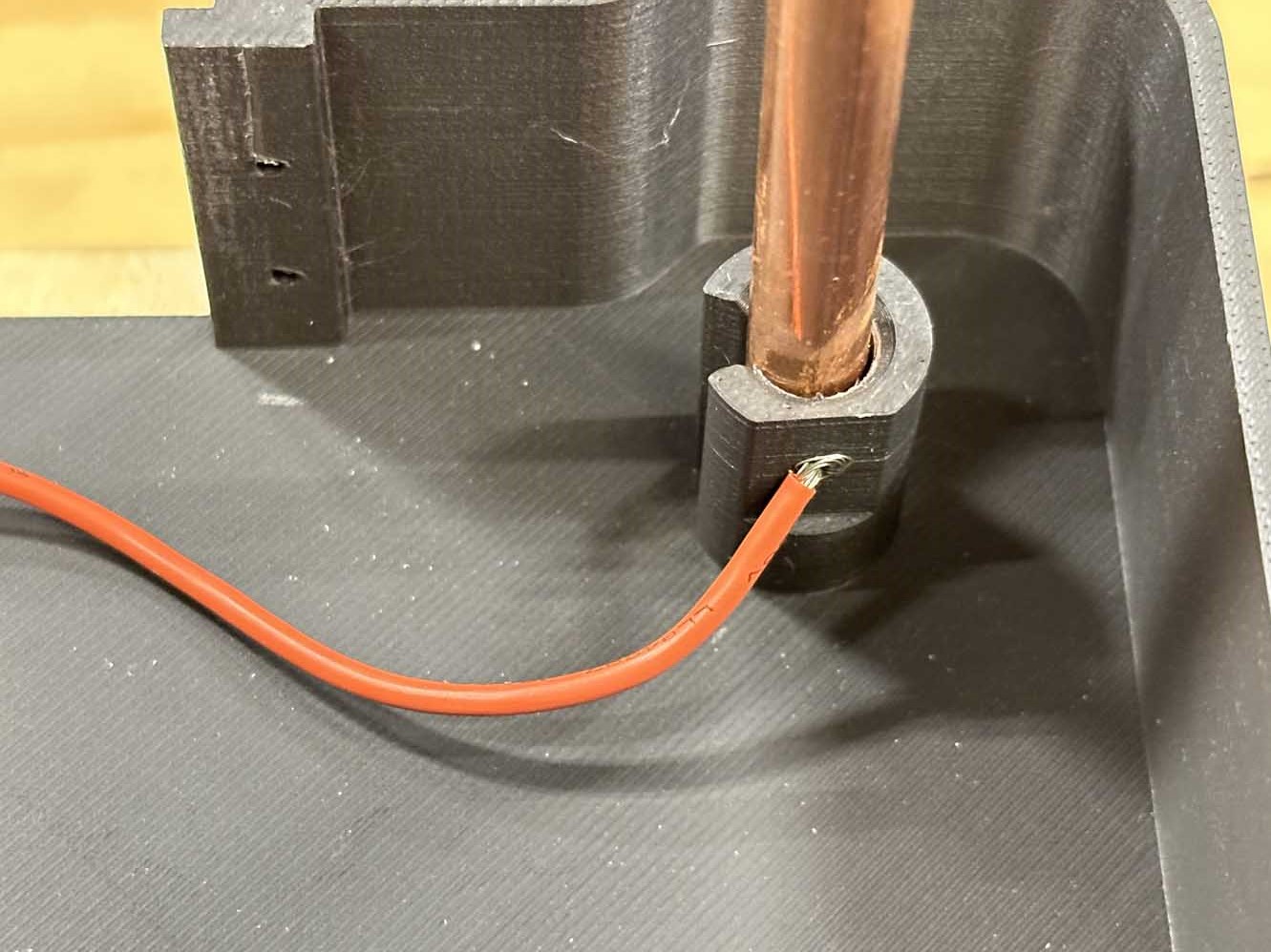
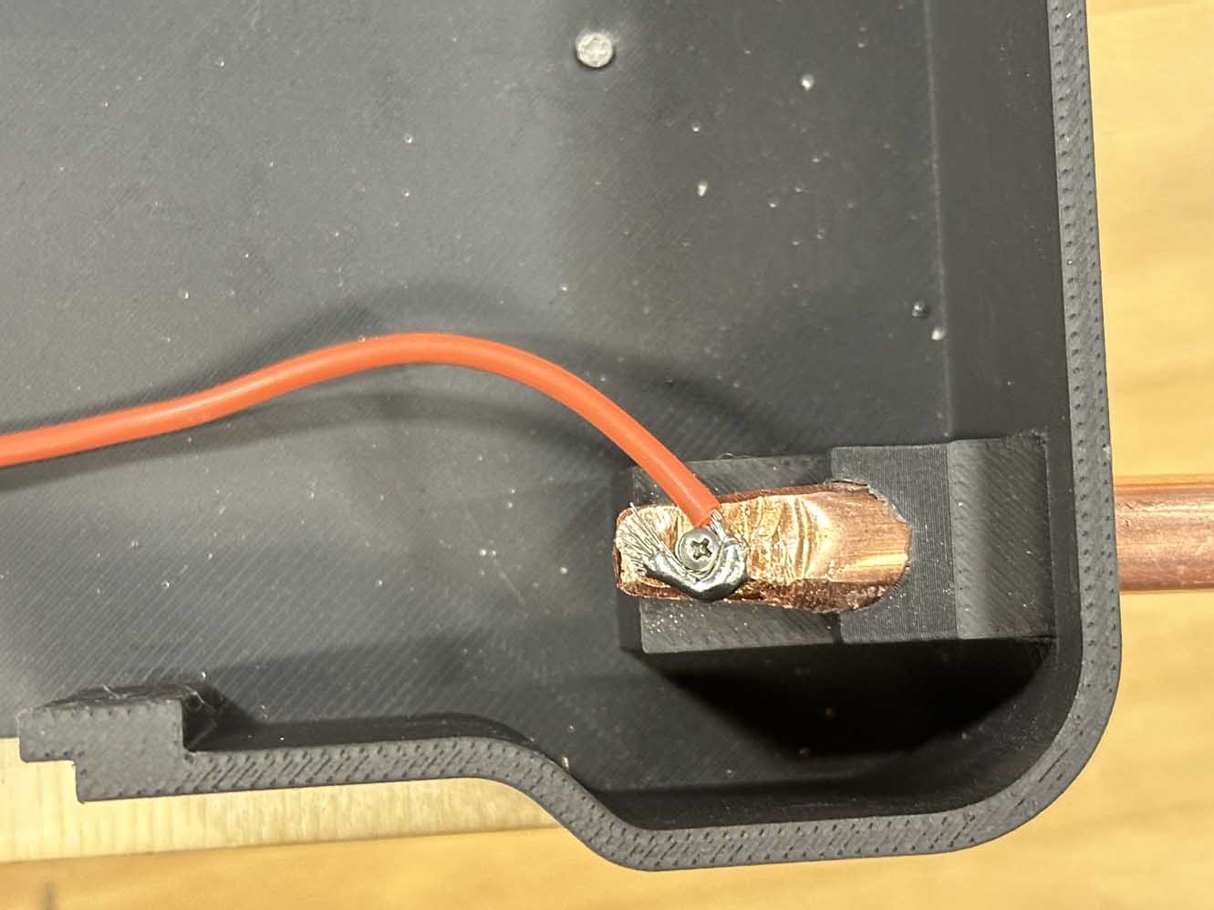
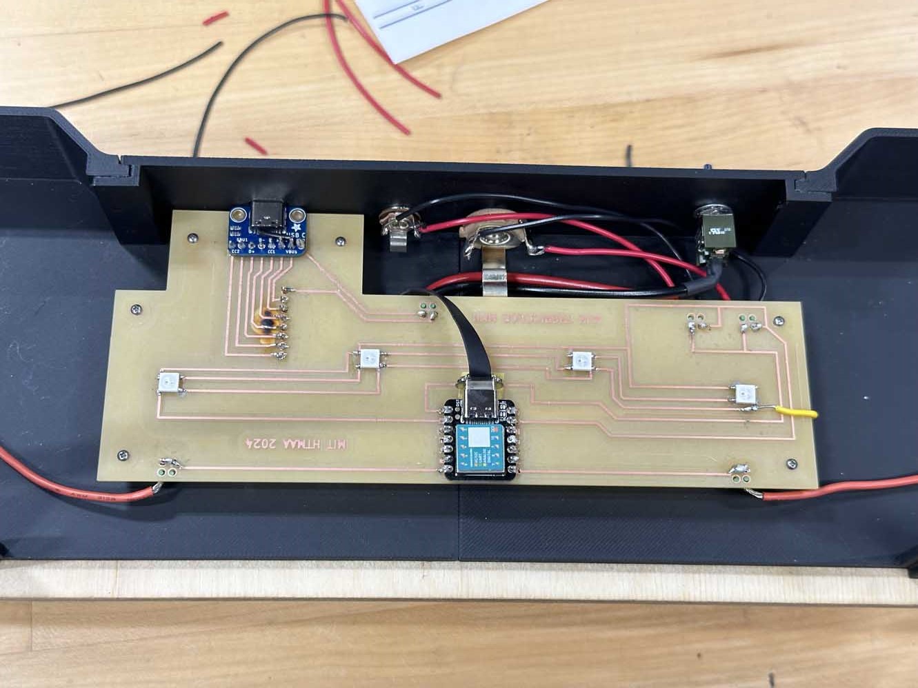
And for the neopixel system integration:
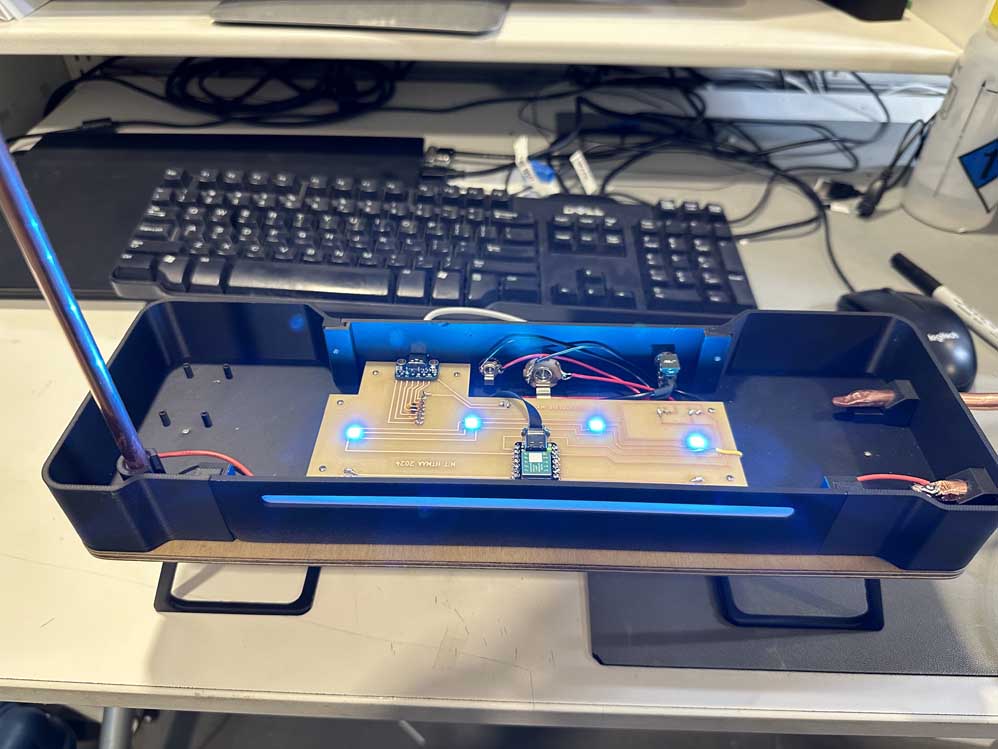
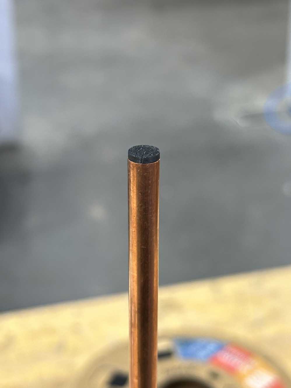
And, last but certainly not least, the icing on the cake - the little antenna plug. Behold.
And with that, we have a completed final project that meets all the requirements! What a wild adventure this has been. Below is a gallery of photos taken by the piano in the Media Lab. I love the way it turned out, I am a big fan.
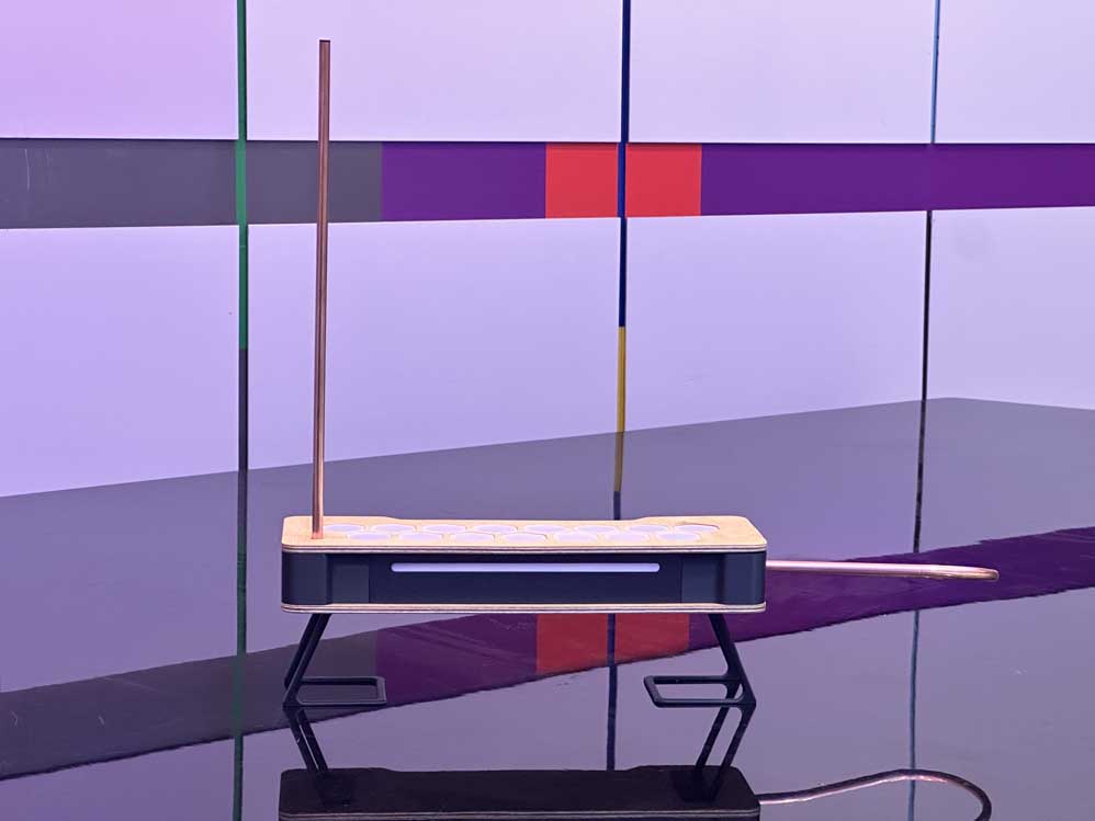
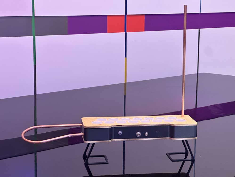
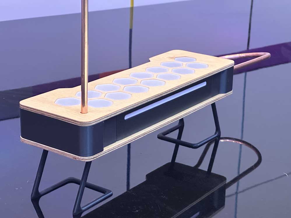
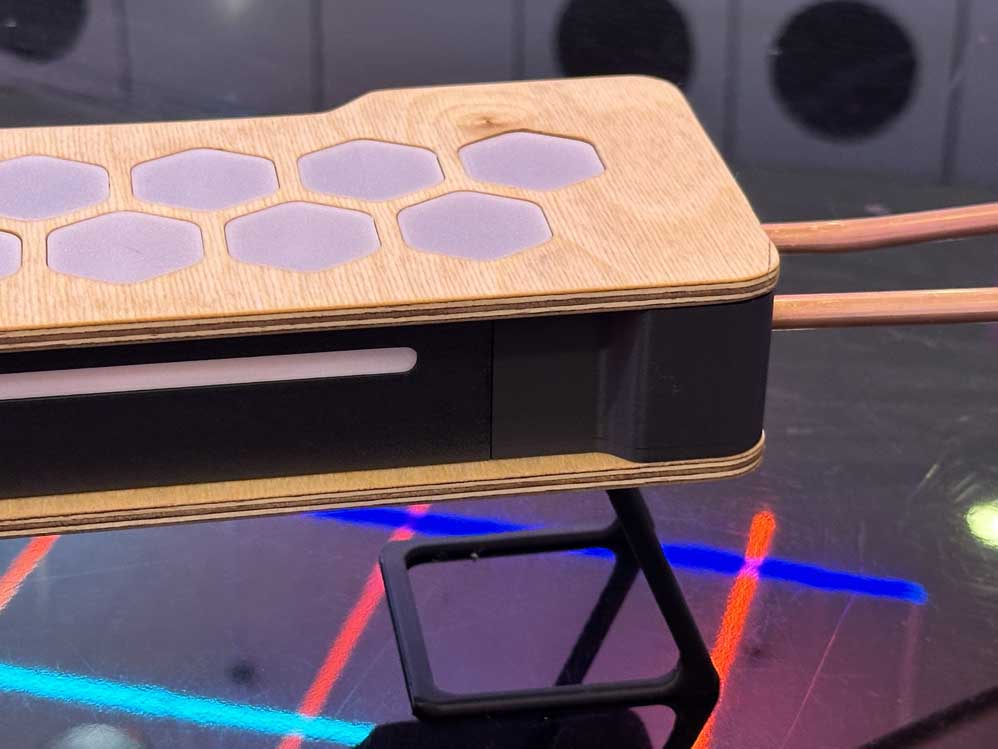
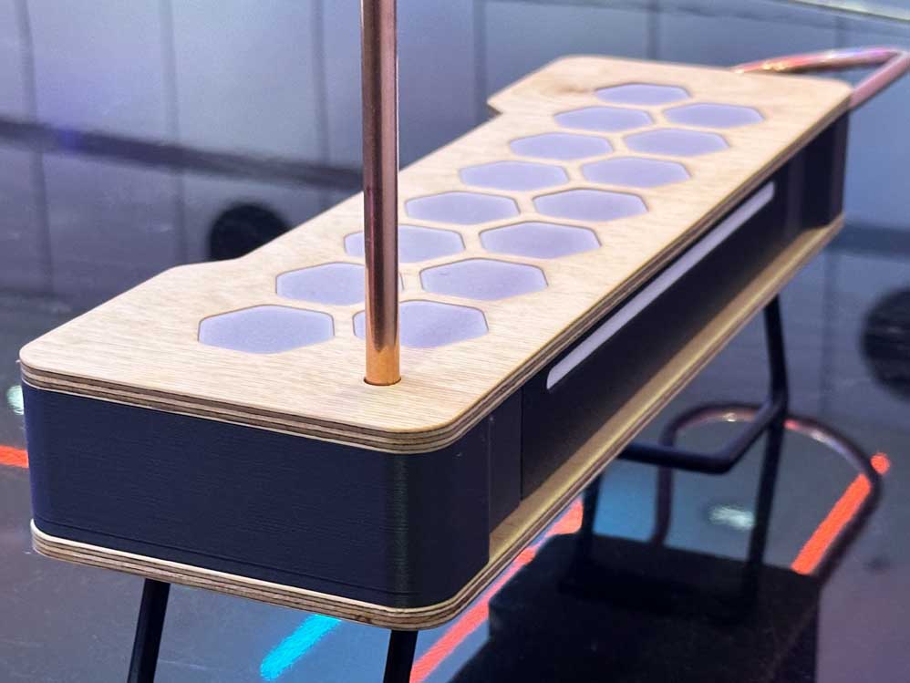
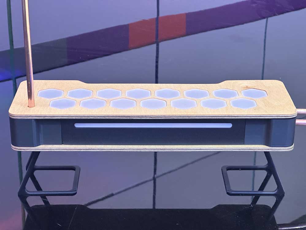
What a thrilling way to conclude the course. This class has been incredible. When I talk to alumni of the class they call it empowering and life changing, and I now see why. This was so fun, so cool, and, despite the long nights and stress, leaves me wanting more. I would take this class n-times over just to make more stuff and push myself in new areas. I asked Neil to teach a spring version of the class that dives into all the wildcard topics, and he expressed interest in the idea, so I really hope it happens. Now that I have this foundation, I feel like an advanced HTMAA would be a thrill. Cheers to you, Neil, for the coolest class at MIT.
