Computer-Controlled Cutting
The goal for this week is to make something ~big~ using the large-scale CNC machines. Each student is given a single sheet of plywood to work with for the week. The CBA lab has a ShopBot with a bed size that can easily accomodate a 4'x8' plywood sheet, and we start the week with the safety training and characterization of the machine's performance parameters. By doing a few test cuts, we can test the runout, alignment, and fixturing for cut parts and the feeds / speeds for wood with our generated tool paths. This process is very similar to the Genmitsu CNC tutorial earlier in the term, but on a larger scale and in only 2D instead of full 3D. This is called 2.5-axis CNC milling because the Z-axis only moves to a few certain heights for the milling process to make (more or less) flat, planar cuts. This works well for plywood since most people wouldn't try to carve funky surfaces with only a half inch to work with across 4'x8' stock (we would be at that machine for hours). I should reiterate the importance of safety for this week. There is little to no room for mistakes since the machine big and powerful.
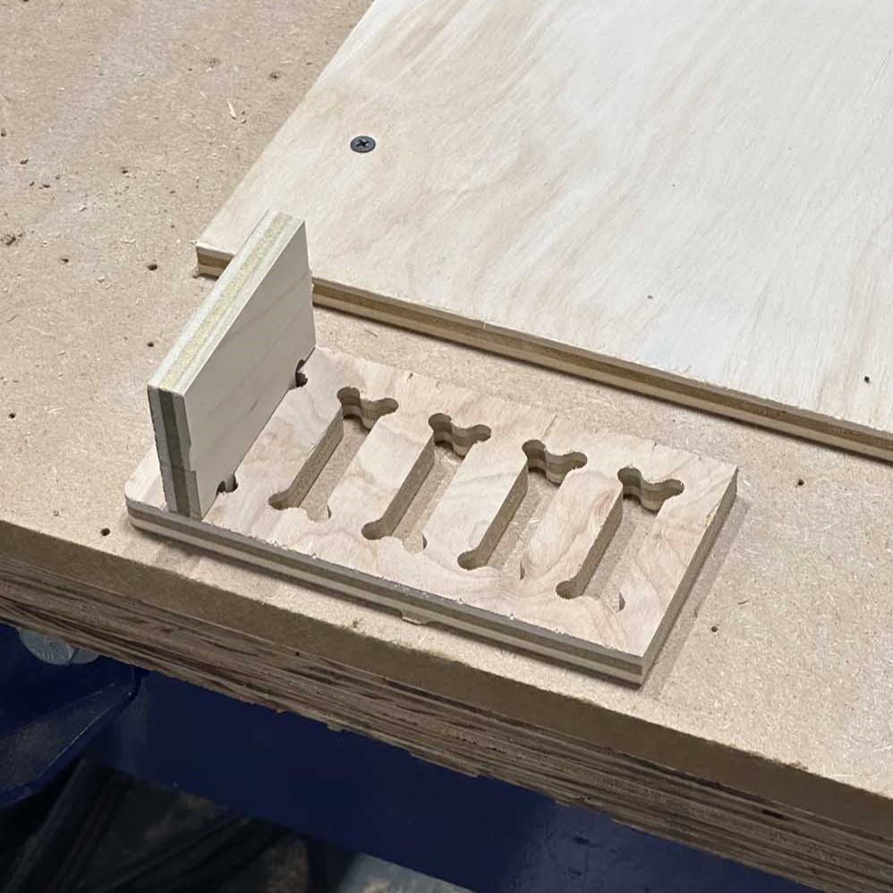
We made some dogbone fixtures to test tolerancing, with the dimensions running from a -2 mil compression fit to a +2 mil compression fit off the nominal dimesions. After that we cut a square and measured it to characterize the runout of the machine. The results of the group assignment are below (thank you Michelle for being the designated photographer for this one). With a spindle rate of 10k RPM and a feed rate of 250in/min, the 3" square was measured to be 3.024" x 3.015", not bad!
With the group assignment taken care of, it's time to start the individual work. Initially, I wanted to make a structure that played off the concept of tensegrity (I'll admit that in lecture Neil said there was no real use for tensegrity and that made me want to find a use for it), but after a few days of trying to come up with a design that I both liked and was feasible, I had to abandon the idea and go with something more attainable for a one-week turnaround and using plywood for construction. There are furniture designs I want to make, but those mostly involve wood turning or steam bending the wood, neither of which are the main point of the week's goals. Something I am in need of and not too invested in the design of is a desk extension for my office here on campus. I find that all of my projects from the class have been piling up and my desk is getting cluttered. A little side desk for storage would be great.
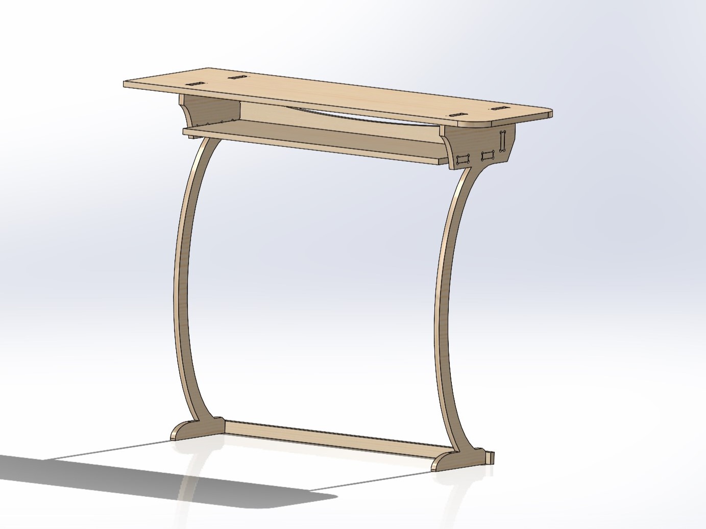
Neil has emphasized the importance of the wording in the weekly assignments, and this week it just says "make something big" not "design and make something big", so I could use a preexisting design, but to me that defeats a lot of the fun of the class. Making my own designs that I'm happy with takes time and might not be a responsible use of time, but to me it feels good to go through the whole process in so many different ways. Something something it will make me a better engineer too I suppose. I took a whole bunch of measurements of the space around my desk and created some keep-in volumes to do my design work in Solidworks. I finally settled on a desk that I enjoy the aesthetics of and should be structurally sound. Did I do a Finite Element Analysis of the design? No. Will it break? Maybe, but that's just the process of living laughing and loving now isn't it (I will say that I probably wouldn't sit on the desk, it might be more of a "display shelf"). Anyways, below is the design. Simple, effective, and has a shelf for items below the desktop. The feet of the desk are designed to hook under the runner next to my desk window. This is kinda hard to describe, but I'll show the concept in a picture once I install the desk.
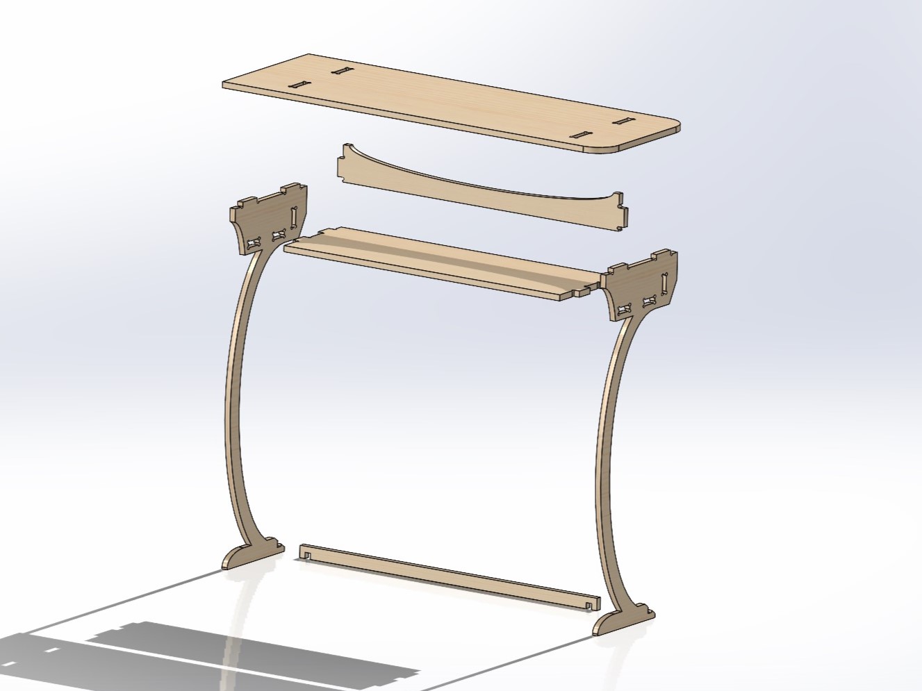
I also included an exploded view to see all the parts clearly and how they assemble. These parts can be arranged into another assembly with the stock wood to show arrangement for milling on the ShopBot. This arrangement is exported from Solidworks as a STEP file and imported to Fusion360 to begin the path planning. The Solidworks arrangement assembly and the STEP import to Fusion are shown below.
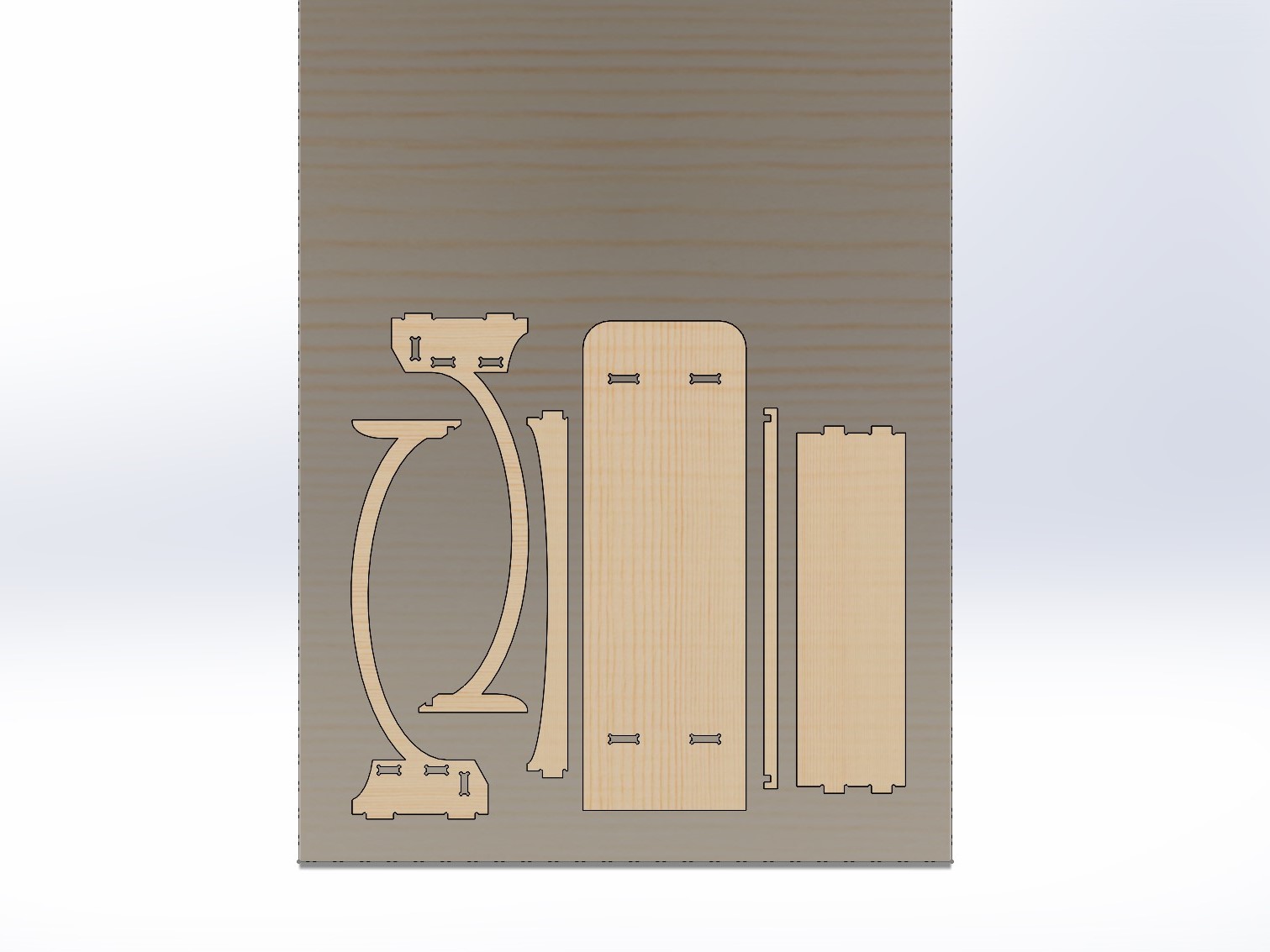
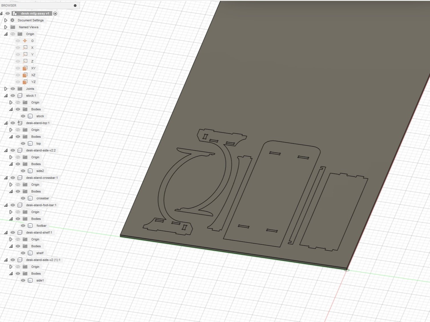
The path planning here is pretty straightforward, same as the Genmitsu. Using the 2D contour tool, the paths are generated for the two tools used: a downcut 0.25" endmill and an upcut 0.25" endmill. The downcut mill is for the first pass since it will make a nice surface finish on the top surface, and then the upcut does the same but for the bottom surface. I deviate just a little from the norm on path planning because some of my joinery I want to be invisible. For the desk top surface, I have the joints going through 2 out of the 3 plywood sheets, so about 0.35" in depth. The inital downcut pass is at -0.2", so I added a second pass for the desktop joints at -0.36" depth to ensure an unobstructed fit. The two downcut contour paths are exported into a single gcode file at the end of the day to keep machine time down to the minimum required for my job. The upcut passes are generated and simulated, and with the full suite of simulations showing no issues and machining what I want milled while leaving what I want left, it's time to export the code and cut some wood!
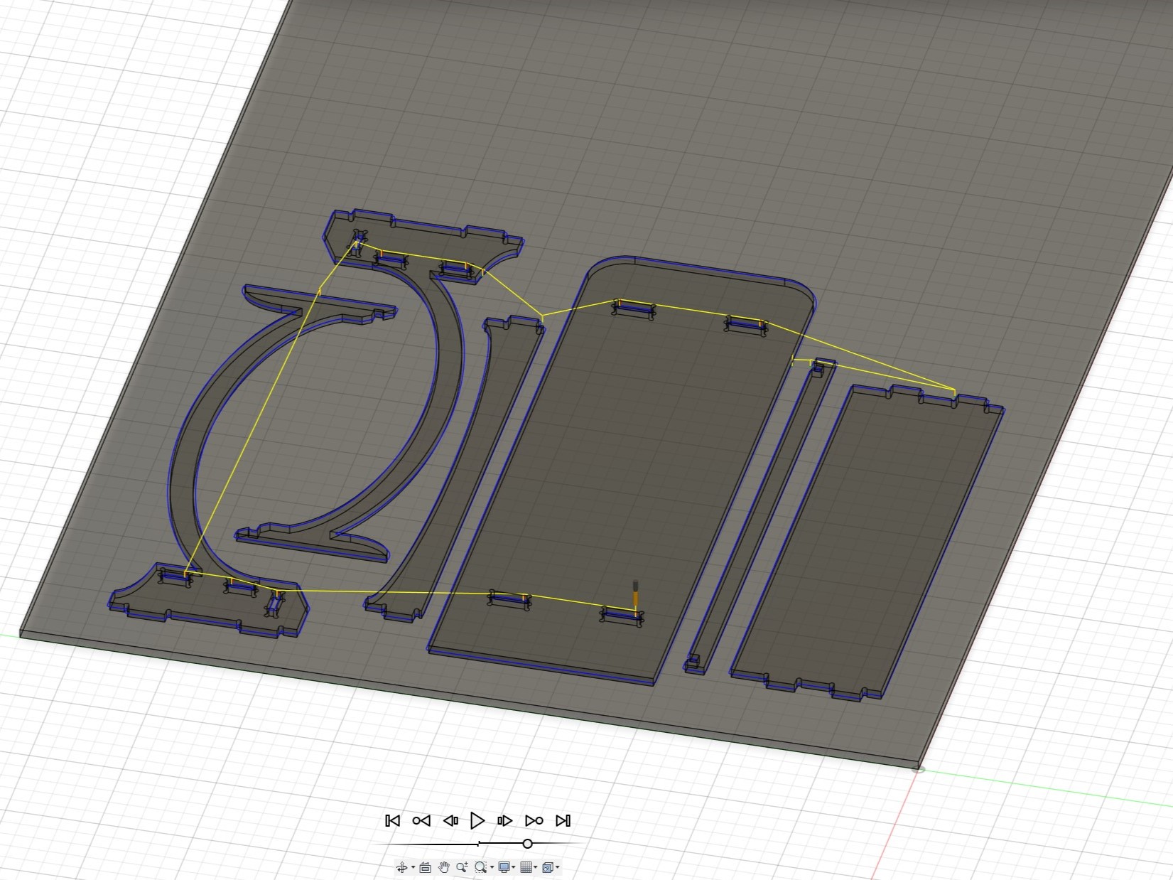
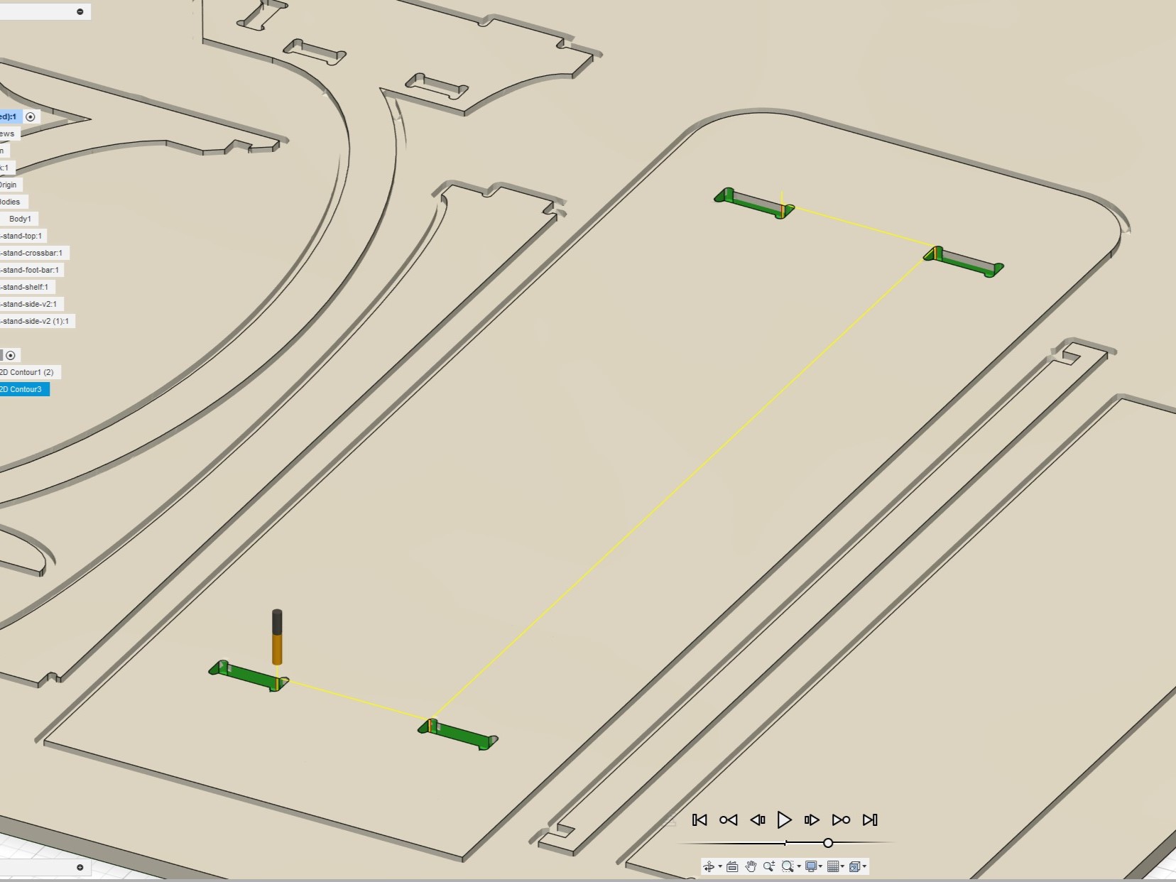
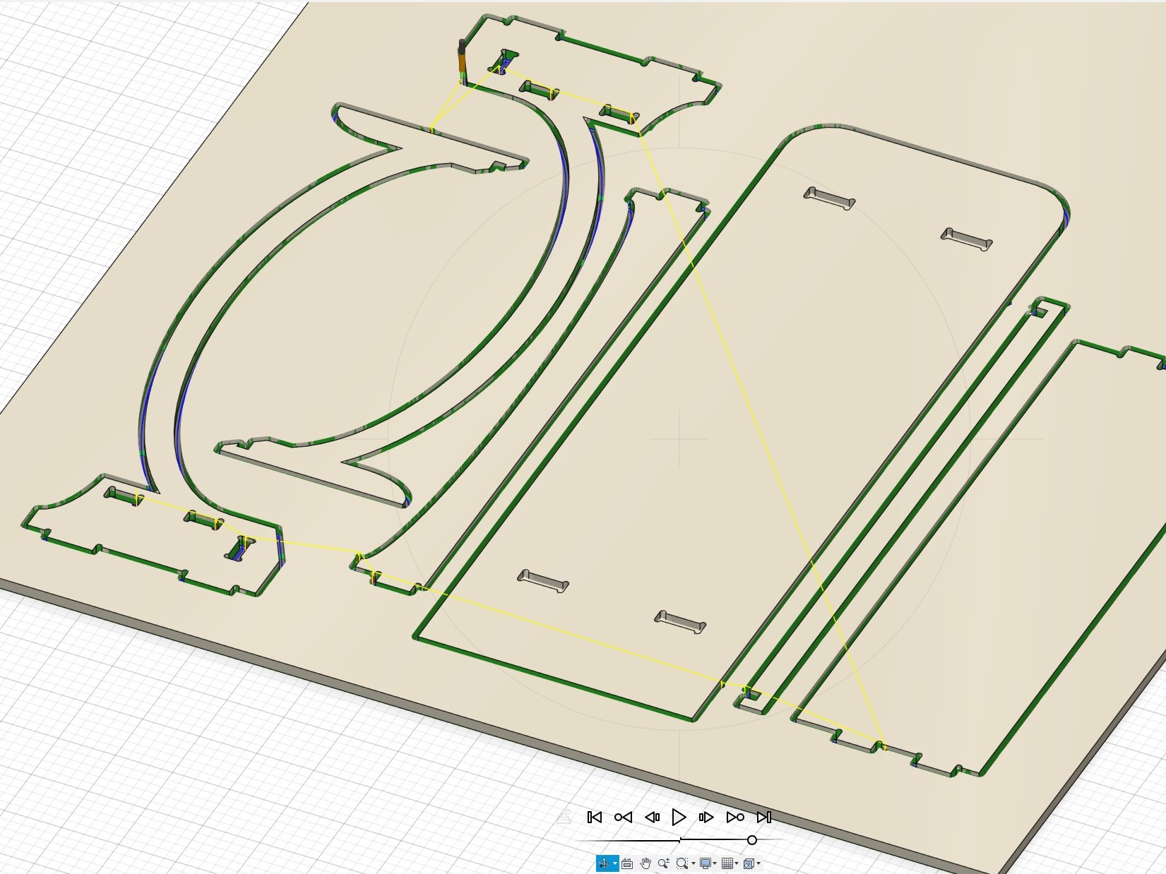
 The process for cutting the wood is straightforward: secure the stock to the ShopBot bed, zero the axes, and upload the GCode. We start with the downcut passes to make sure the top surface of the stock is kept in good condition, followed by my downcut pass for the dogbone pockets of the desktop. After that, the milling bit is changed for the upcut endmill, the z-axis is redefined, and the final passes are made. The process of zeroing the axis, downcut and upcut passes are shown below.
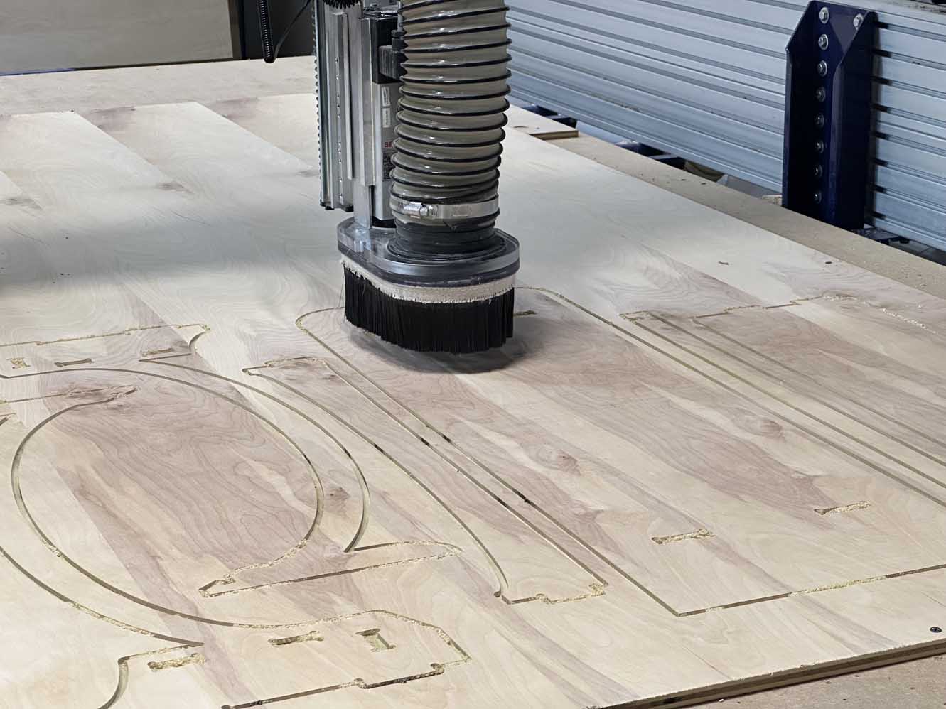
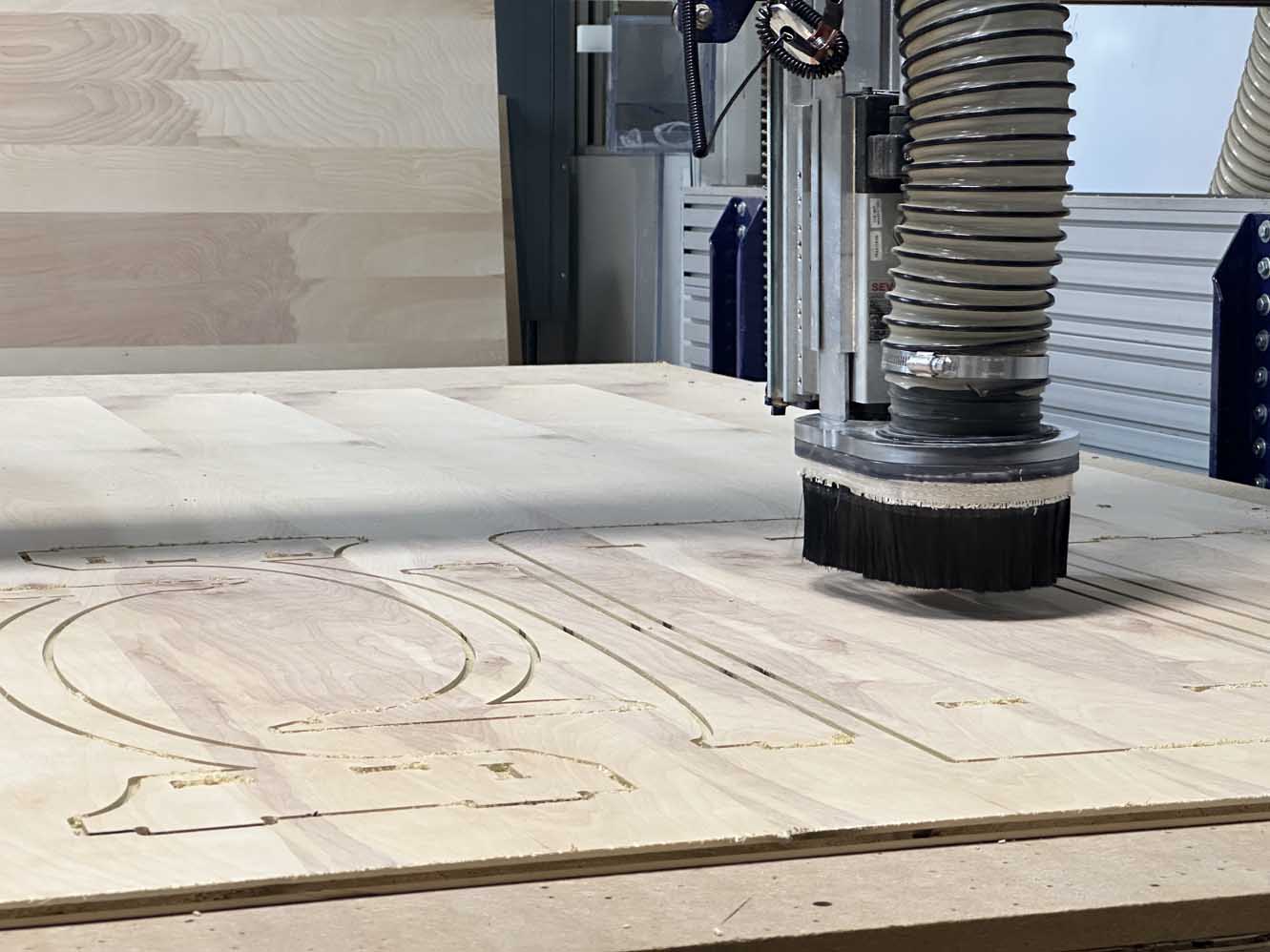
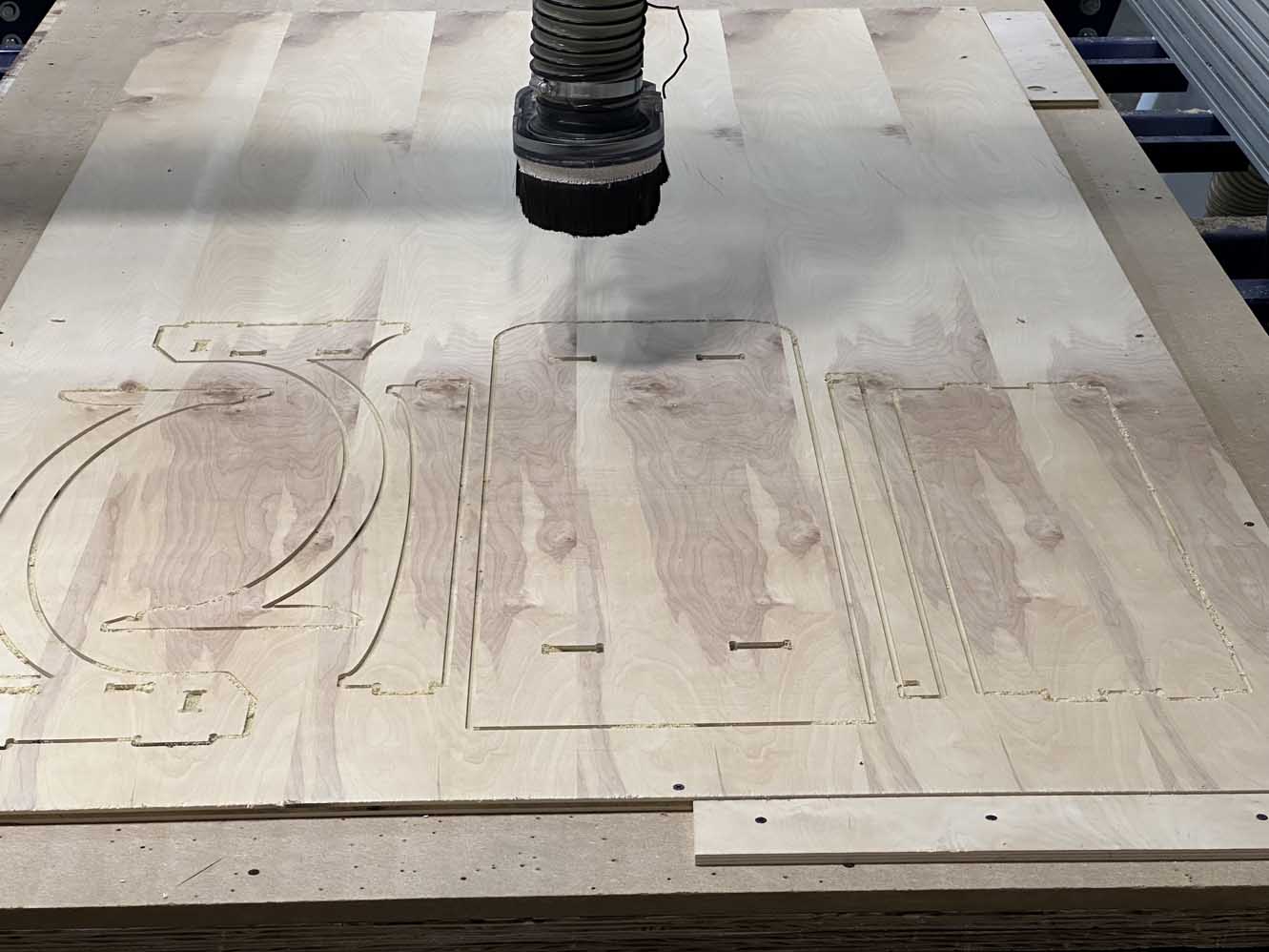
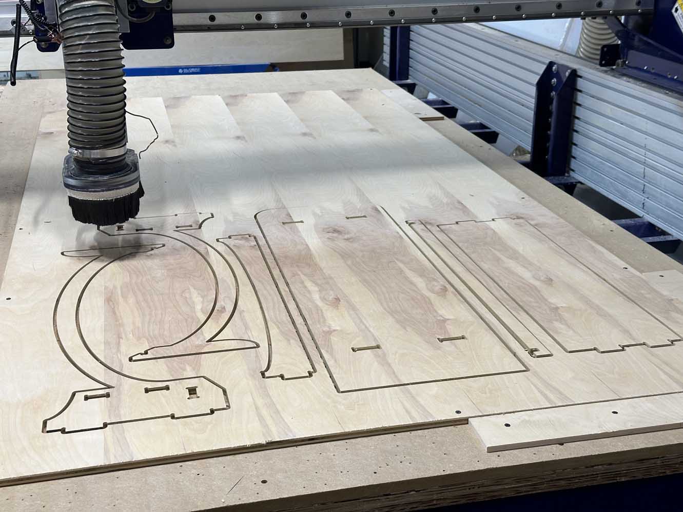
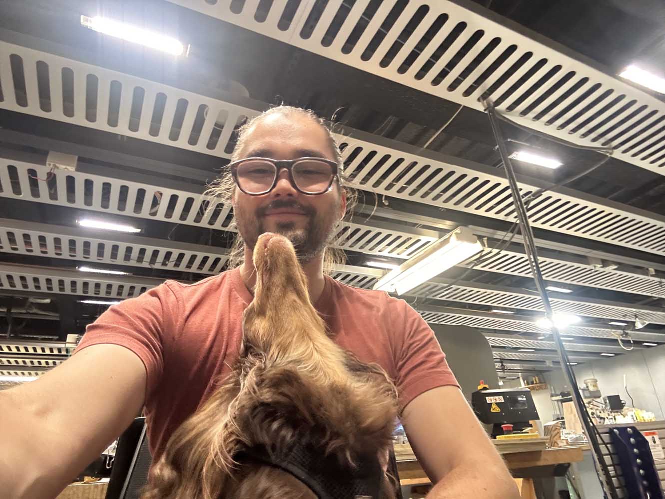
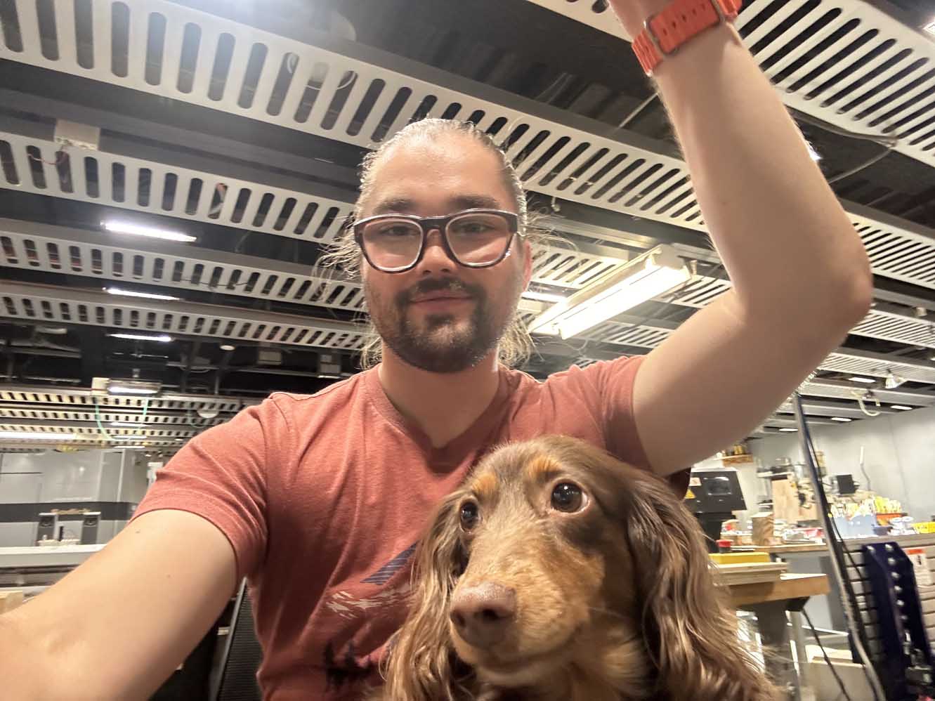
 For this week we needed to cut with buddies in the lab for safety. I had the great pleasure of being buddies with one of our most experienced classmates, since I seem them at every lecture, recitation, and actively participating in every lab training. Below is a few shots of me with my new bff, Moose.
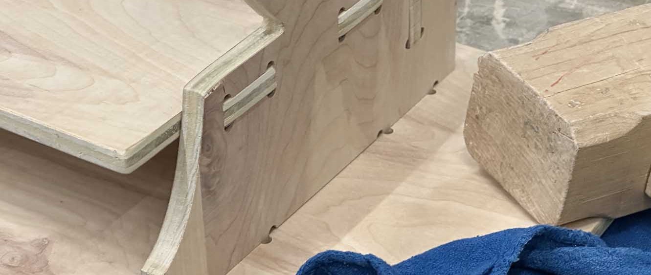
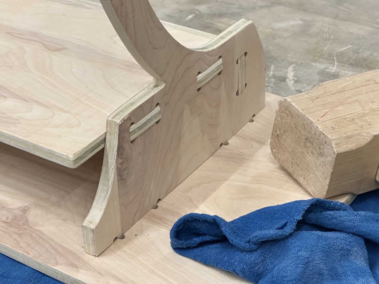
Upon inspection of the parts, it was clear that some areas were machined better than others. Whether this is due to disrepencies in the alignment of the machine or thickness of the plywood, the result is that some tabs were milled properly and some were not. Thankfully all of the parts were milled to acceptable tolerances, although one part did come loose from the tabs since all were milled away. The pockets for the desktop were milled to the desired depth, so that is at least good. Below are the pockets and tabs.
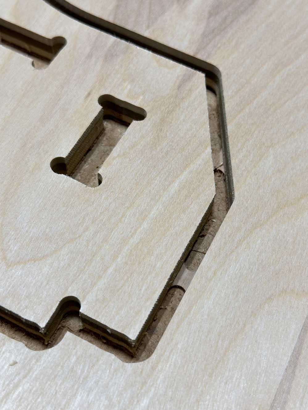
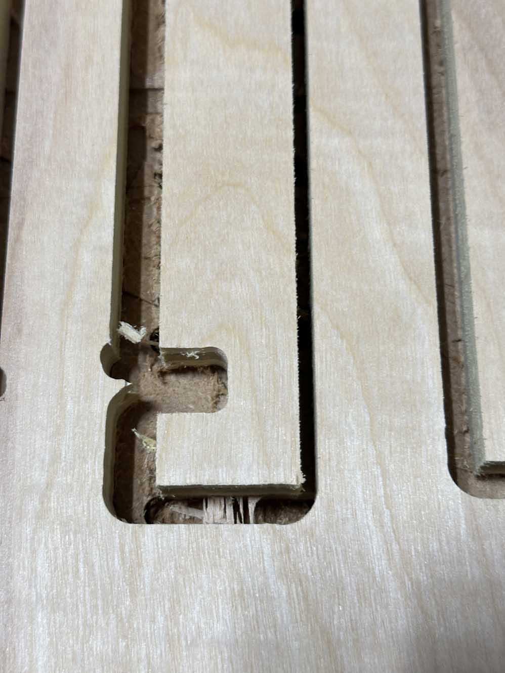
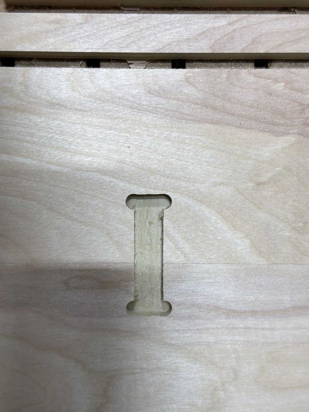
You can also see that for the cutout in the middle picture above that I forgot to add dogbones to make it compliant with the pocket it fits into (and likewise for the other pocket). This completely slipped my mind when designing the support bar. Oh well. I can fix it in post - just file away the excess material into a square joint. After a quick test assembly of a few parts to ensure they fit and are compliant, the sanding and finishing work begins!
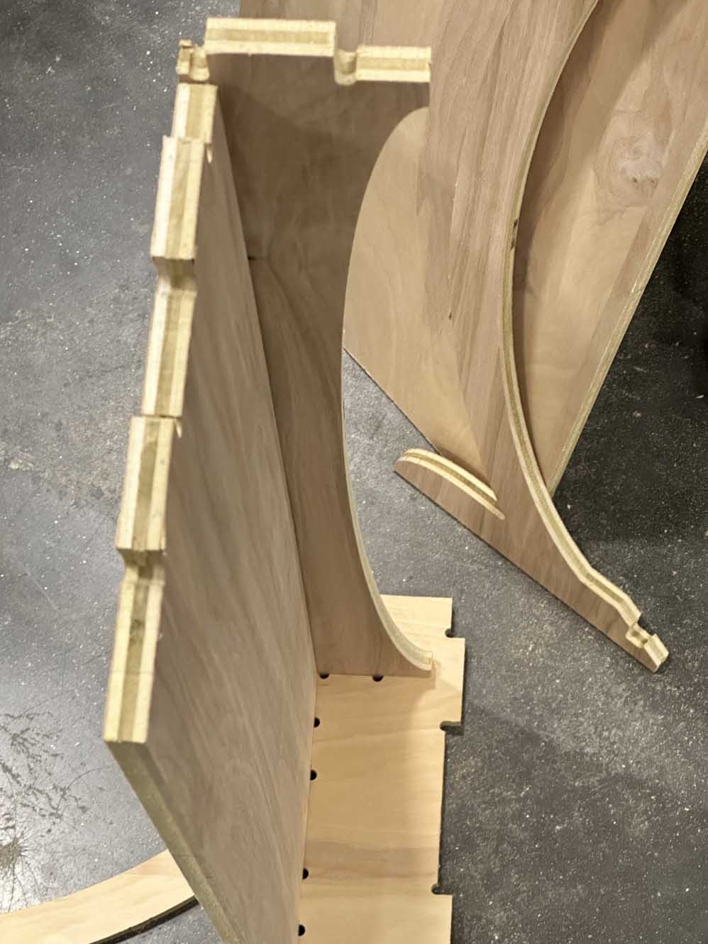
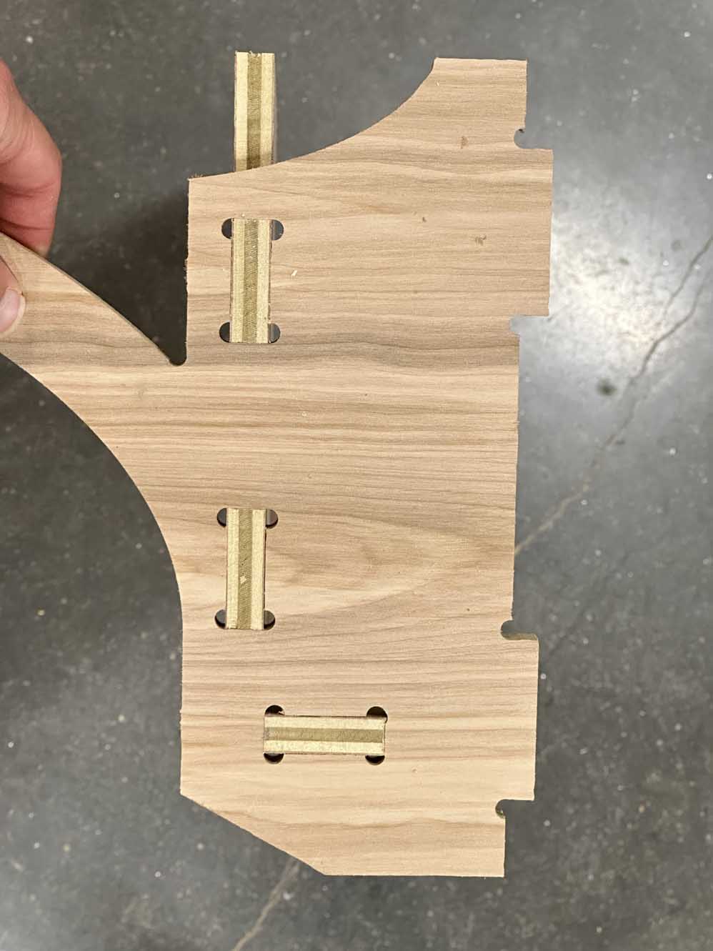
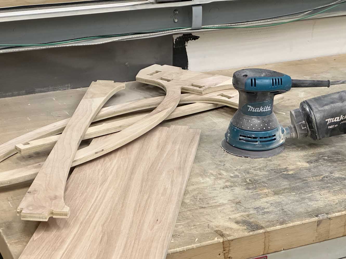
Sanding and finishing the desk was a lot of fun. I eat this stuff up. Absolutely love it. As far as this whole class has been, this week I have certainly felt the most at home and in my element so-to-say. Below is the sanding process, and after the parts were sanded with some 600 grit I cleaned the pieces and reassembled them into the final desk geometry.
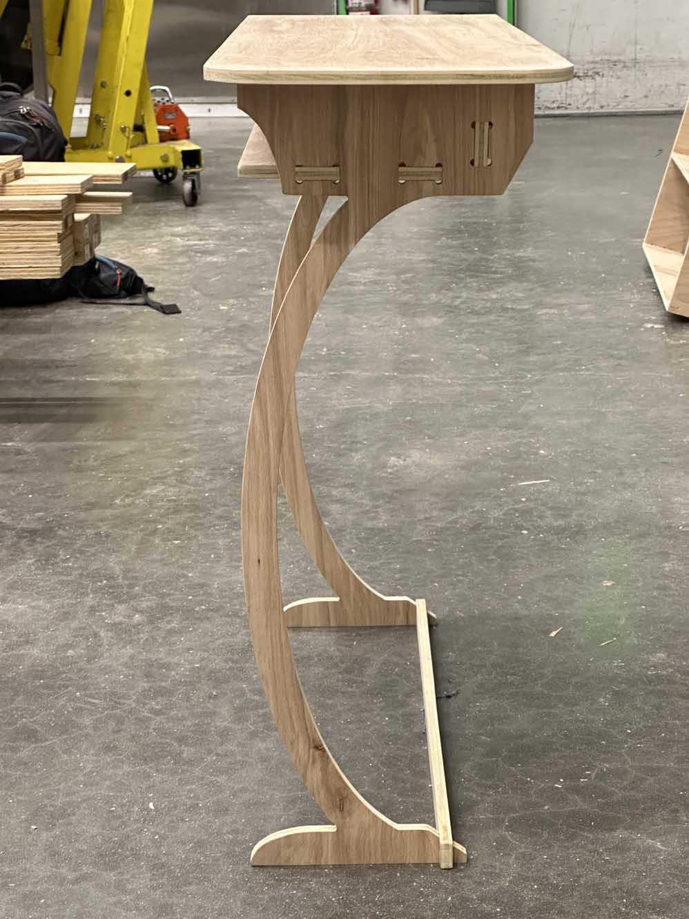
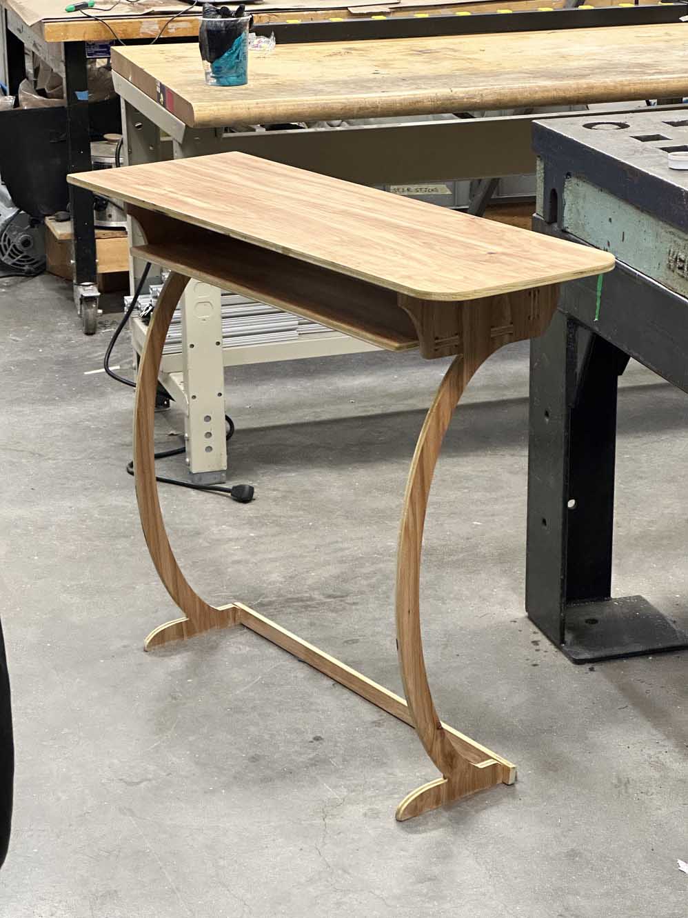
At this point I discovered that the sanded desk had just enough give in the joints to make the shear plane motion more than I had initially anticipated with the design. I knew some shearing would be present, but there were 1mm gaps in the minor dimension of the dogbones that allowed for ~just~ enough shearing that I wanted to eliminate. This became more apparent as I oiled the desk. I used a Danish Oil to preserve the color of the wood (this was totally intentional and absolutely not a result of me not having any stain on hand and only having access to Danish Oil because Jonny was kind enough to share). Anywho, below is the desk assembled, pre and post oil.
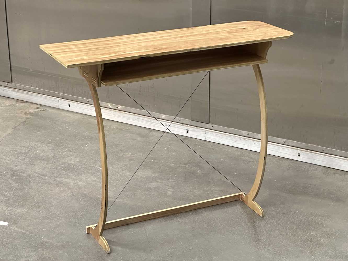
After the oil penetrated the wood, I decided to add in some steel cables to eliminate the shearing DOF that the current design has. I drilled some small holes and attached eyebolts to the desk then crimped steel cable in an X pattern on the back side of the desk, shown below. This technique is widely used since each cable eliminates the shear in the direction for which it remains in tension, while the other slackens under the compressive load. Since there are two cables, the compliment each other in eliminating one direction of shear each, thus completely eliminating the shear plane DOF the desk had.
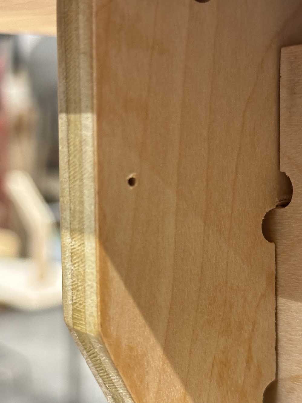
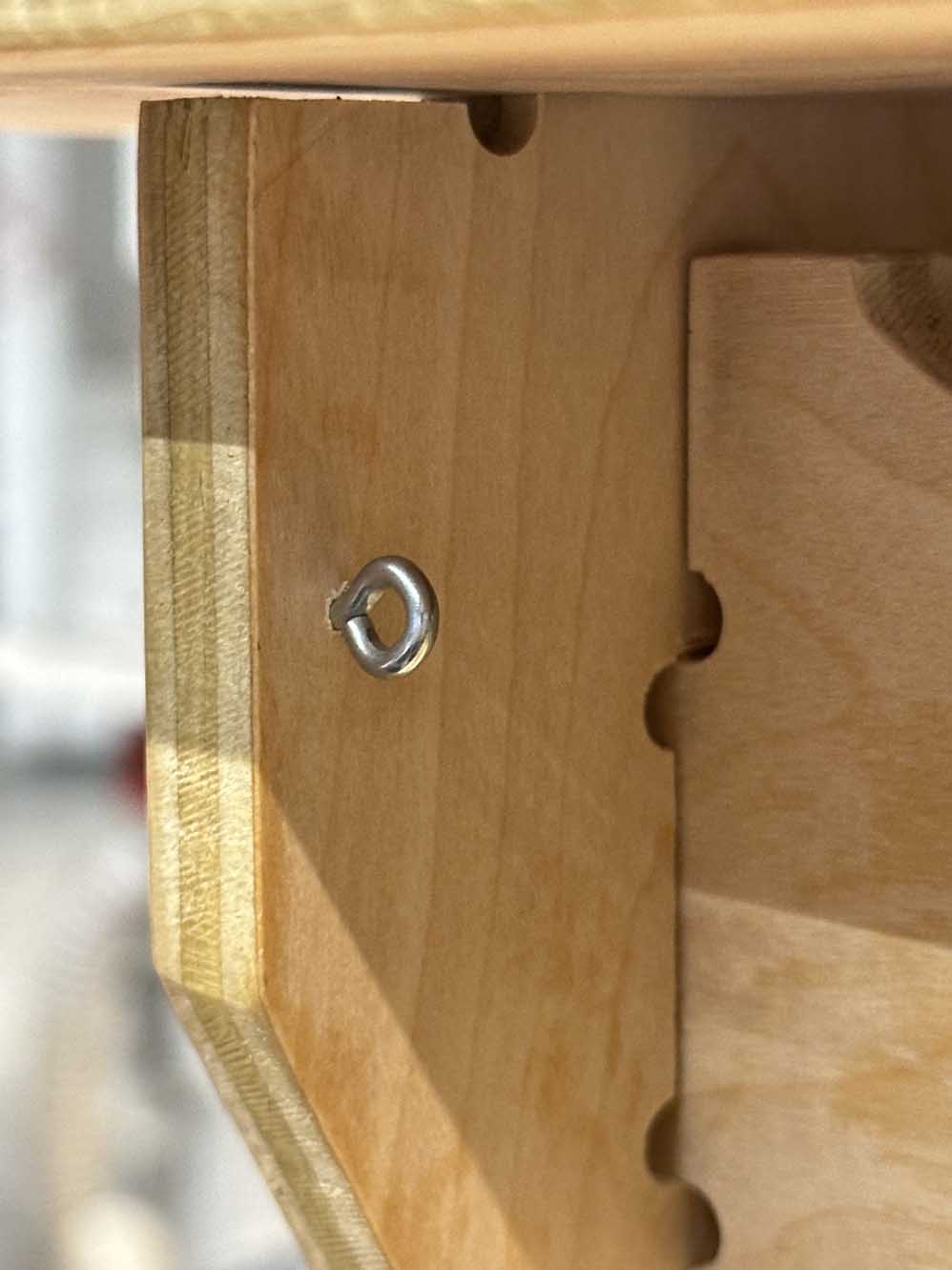
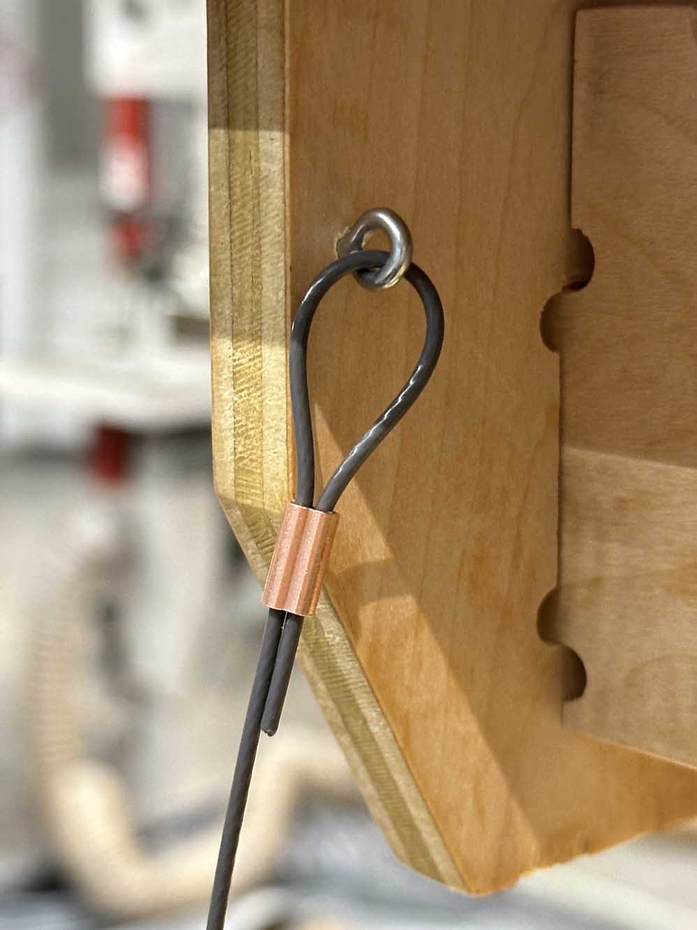
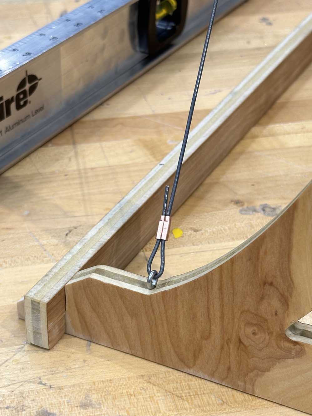
While tensioning the cables, I used a level to ensure the desktop was not being skewed in one direction or the other since I had to guesstimate the tension by vibes. All was good though, and the final product is shown below! I will update this in the future when I get the desk back to my office and show it installed (and I do sincerely hope I did my measurements and tolerances right otherwise I will be very sad). This was a great week. 11/10. Great design challenge, great avenue to be expressive and make something both practical and aesthetic. This confims my desire to live in the woods alone and become a carpenter.
As always, here are the files for this week
