Output Devices
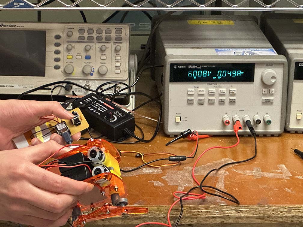
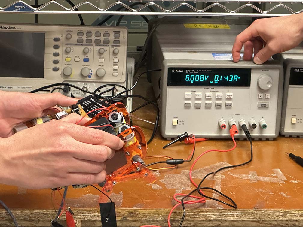
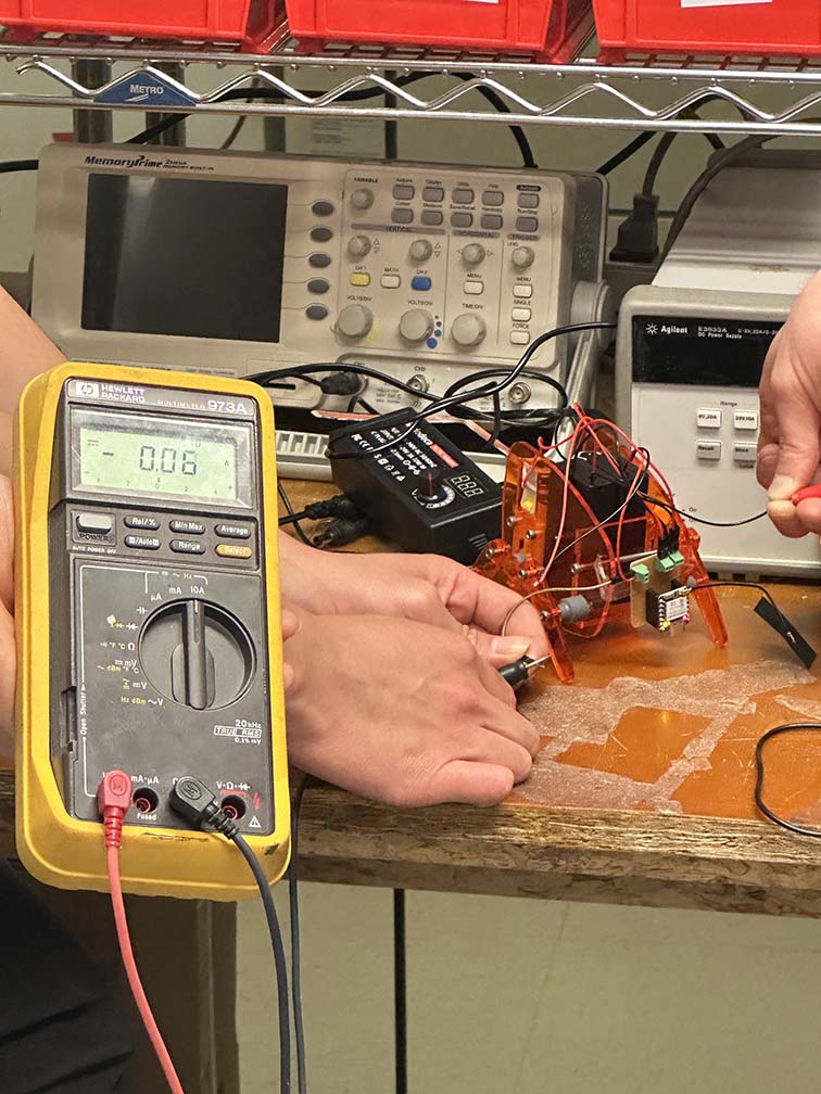
This week the focus is on output devices - things that do things. This week can get a bit hairy with power electronics and safety, so the group assignment is designed to measure current draw for certain output devices to maintain both a sense of awareness for the power we will be handling in addition to a healthy sense of caution for the danger it poses. Marcello brought in a little walking robot for us to investigate. We hooked up the device to a benchtop power supply and set the voltage to watch the current draw. Below you can see the nominal current draw (just to run the microcontroller), and then when one motor and both motor are activated, respectively. Notice how the current steps up in a linear fashion from the offset of the controller.
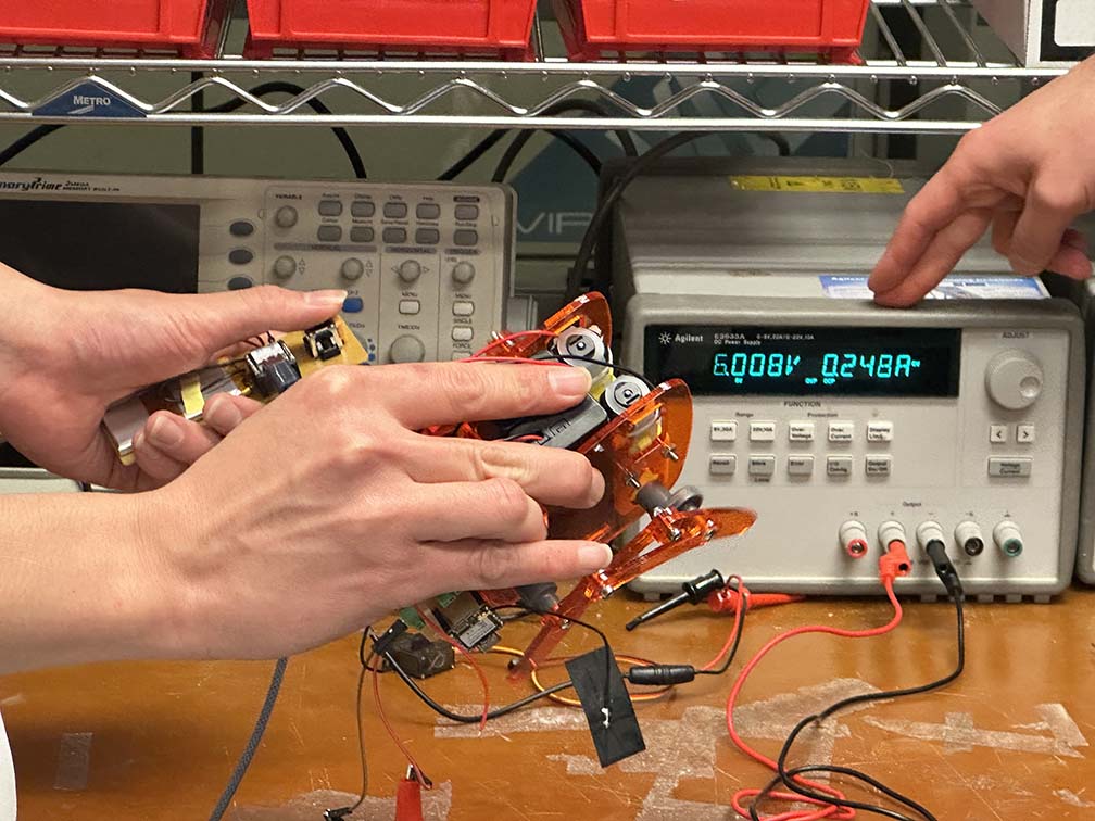
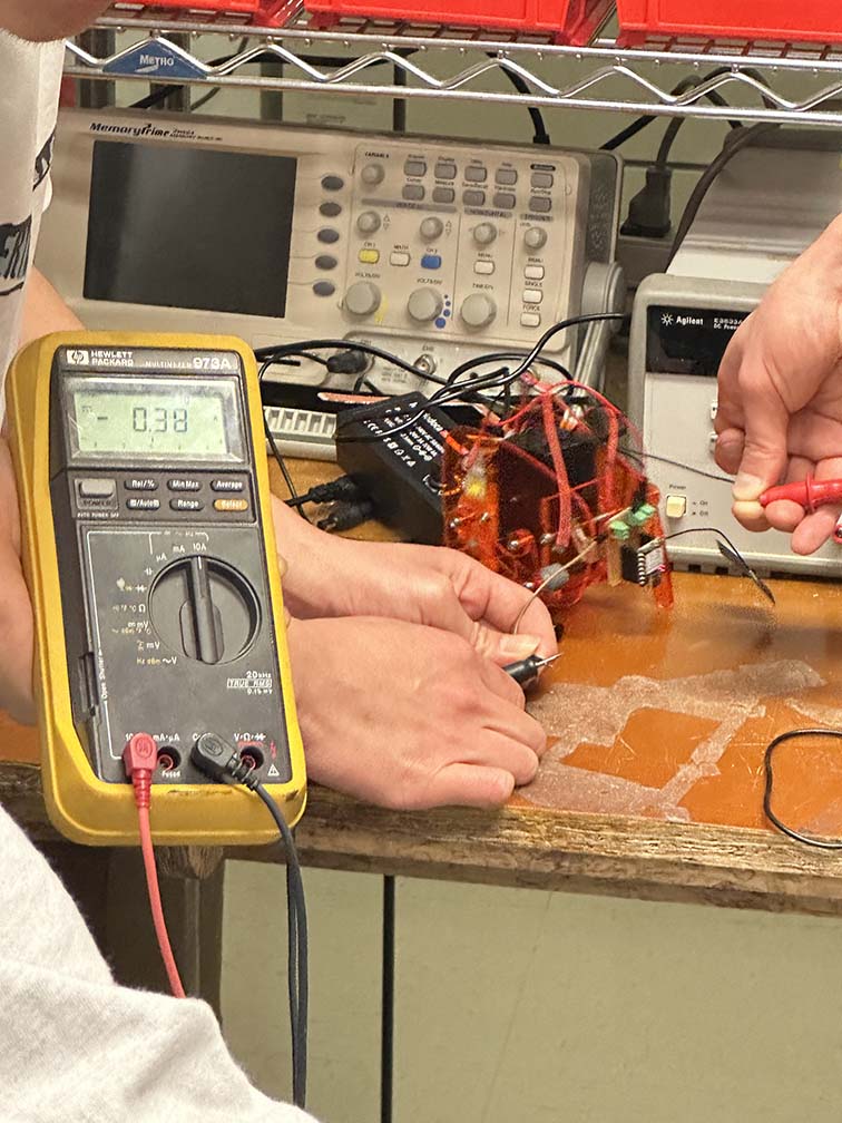
This can also be seen with a multimeter. We replaced the power supply in the robot with the LiPo batteries Marcellow had and measured the current once again. The readings were slightly different (likely as a result of the different supply voltage of the batteries), but within the same ballpark as with the power supply, shown below for the nominal (left) and both motors running (right).
Building on last week (input devices), my goal is to build a Theremin - the musical instrument you play by moving your bands in the air. Last week I was able to get the native QTouch working on the XIAO SAMD21, which was super cool, and this week I needed to map those inputs to a sound output. Easier said than done, but it should be relatively straightforward.
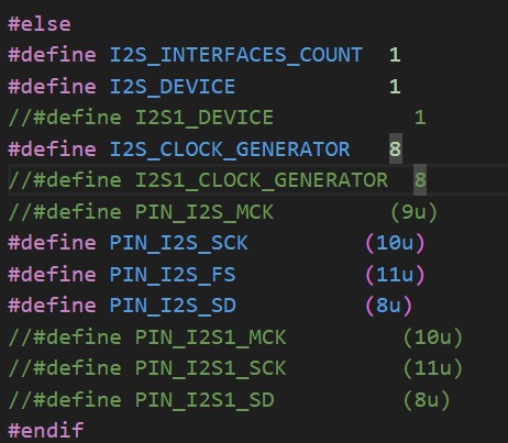 In the world of sound and speakers, there are a limited number of ways to achieve high-quality audio. Since I want to build a musical instrument, I would like the sound quality to remain uncompromised; however, building the entire analog circuitry for a genuine Theremin is out of the scope for the week, so let's go with the best digital sound available - I2S. I2S, or Inter-circuit Integrated Sound, is an audio data protocol developed to send high-quality audio signals (typically .wav files), to a preamp and then a line-level speaker. The SAMD21 has a single I2S port and it just so happens that it is broken out on the XIAO. While Seeed Studios does not advertise that the XIAO supports I2S, some finagling of the variant.h files can re-map the microcontroller logic to support I2S, seen to the right.
Narrator: Finagling of the variant.h file could not, in fact, re-map the logic of the microcontroller to support I2S.
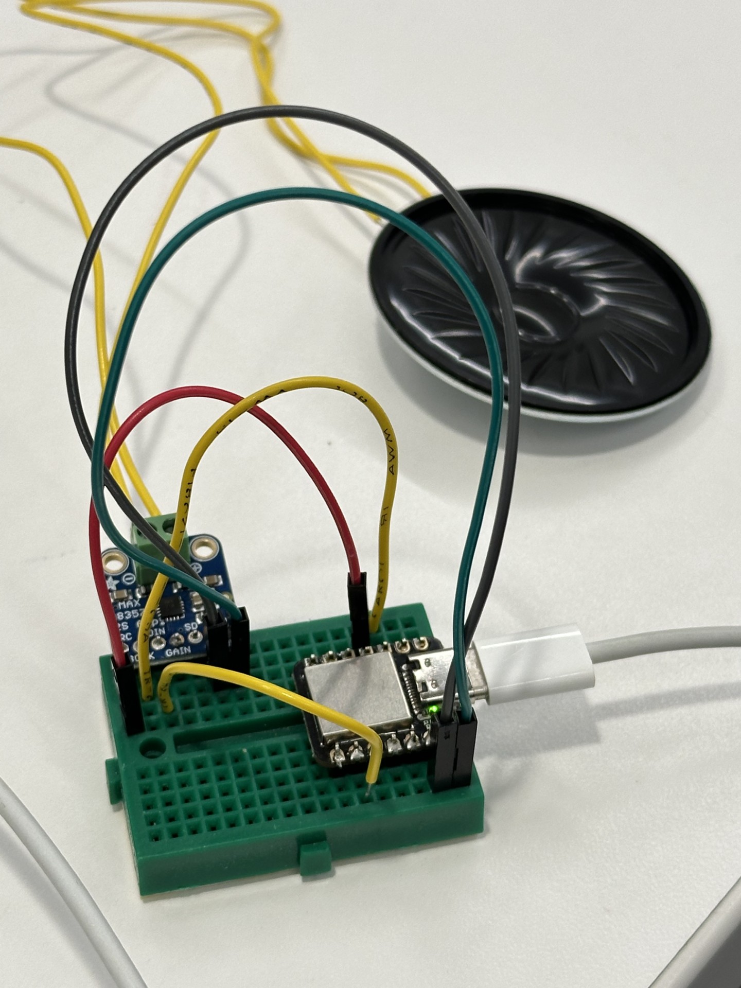 After a rather defeating 6 hours of trying to get I2S to work, neither Quentin nor I could get sound out of the speaker. The little development setup for this frivolous attempt is shown to the left. The more I try to use I2S the more I'm convinced it is fake. Not real. It's a sick, practical joke that preys on the hubris of fools like me. I2S is not my only sound option, and if I can't bring sound into this world as a benevolent creator then I will extract it from the microcrontroller as a malevolent god. Time to solder a aux port directly to the DAC of the SAMD21 and get a signal.
As it turns out, Quentin made sound for his capacitive touch piano using the SAMD21 native DAC and QTouch. This is great because it provides a solid framework to get the DAC speaker running and how to map that to QTouch inputs. I heavily relied on his code for this one, and the wiring is incredibly simple. I used the breakout circuit I made last week for the XIAO and QTouch and milled an separate Aux circuit for both a passive speaker hookup as well as a Aux speaker output. The connections are simple - this is a single channel audio output so the L/R sides of the aux can be both connected to the DAC and the ground to ground.
Voila, we have sound.
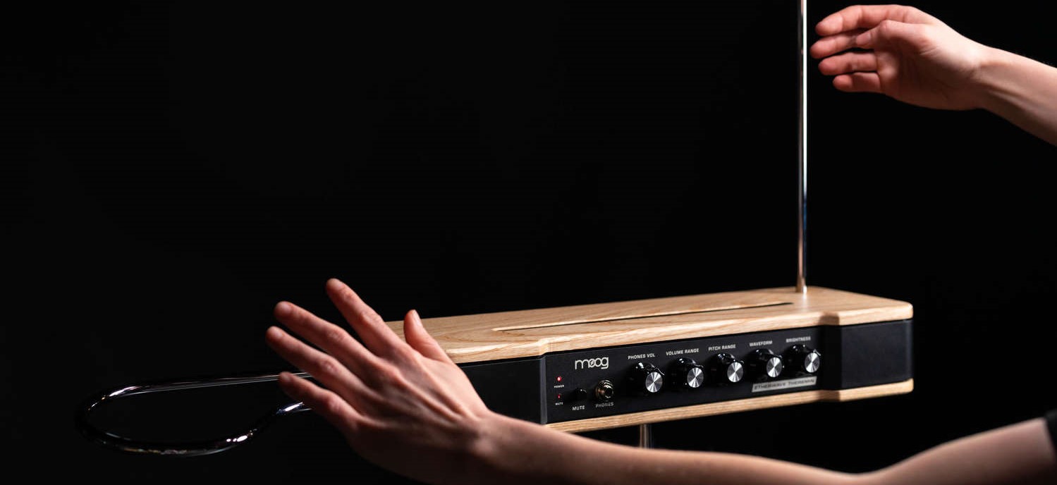
With this, the only thing that remains is software controls and building a physical enclosure. Lets start with the physical enclosure. The geometry of the whole setup is very important since the Qtouch is measuring changes in capacitance across it's terminals, and in order to properly baseline the software values for sound mapping, I need to make sure it doesn't change too much. Moog is the leading manufacturer of Theremins today, and their design is rather elegant, so I think I will take inspiration and print a housing box that reflects their design. Below is the CAD for the Theremin box.
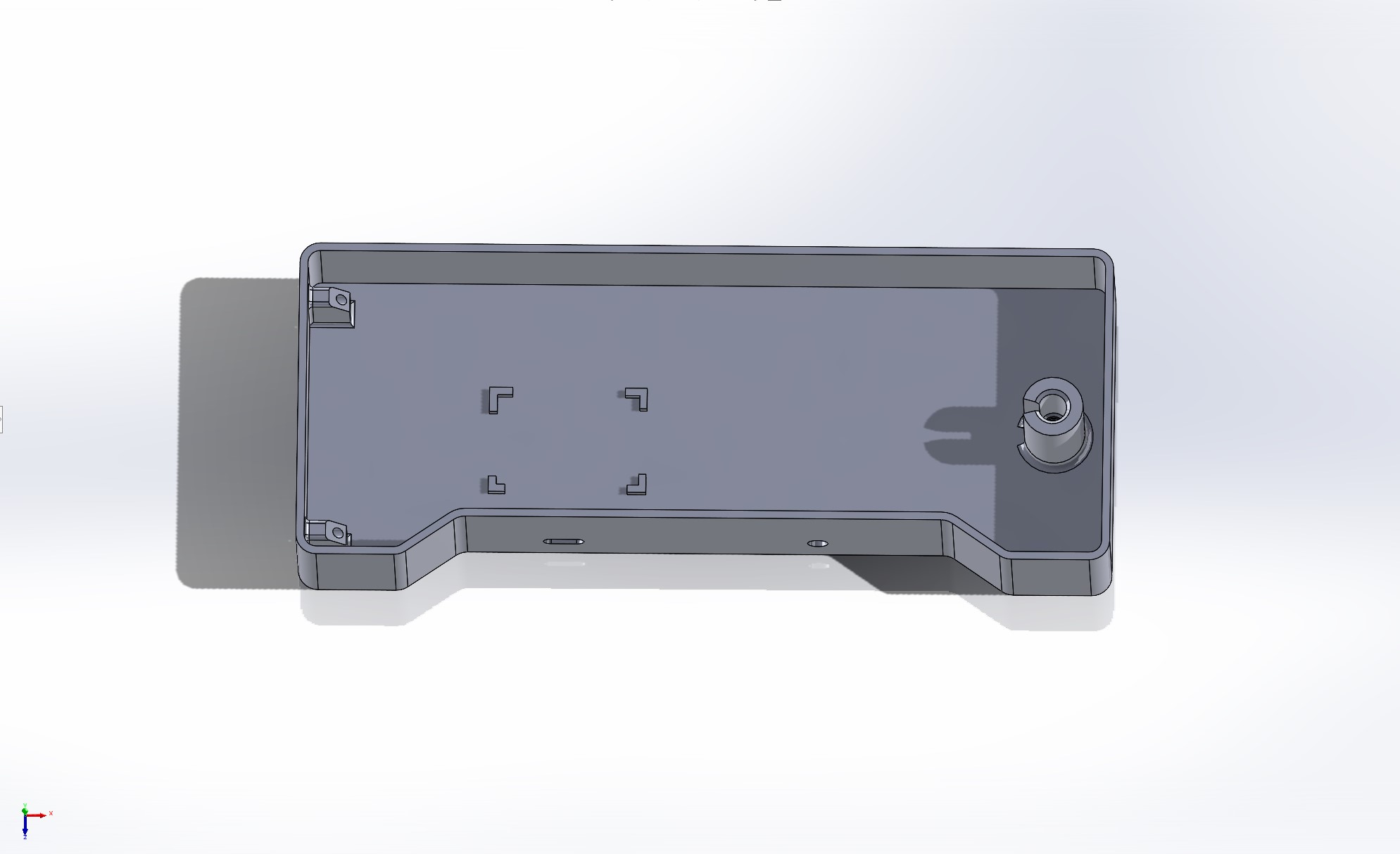
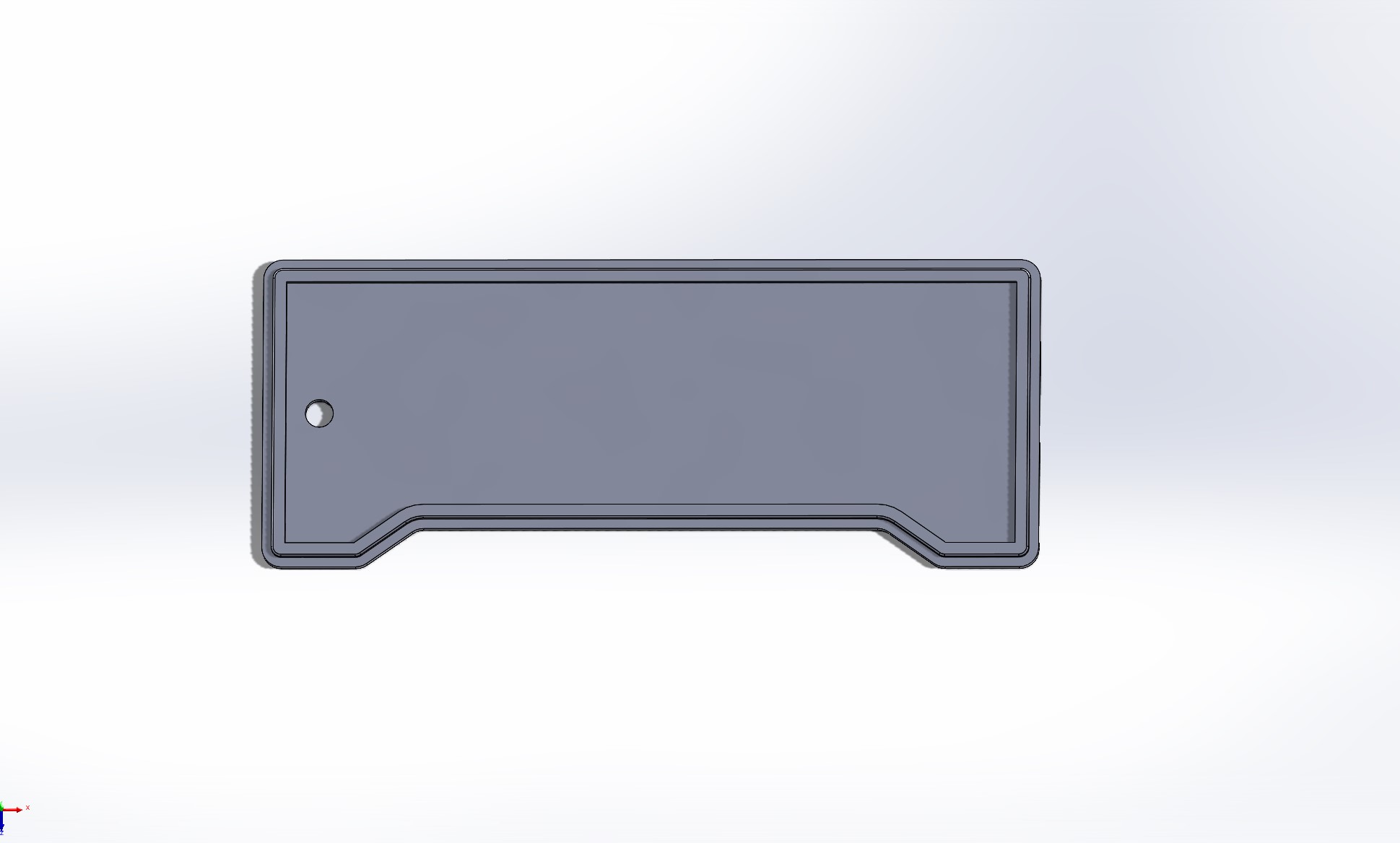
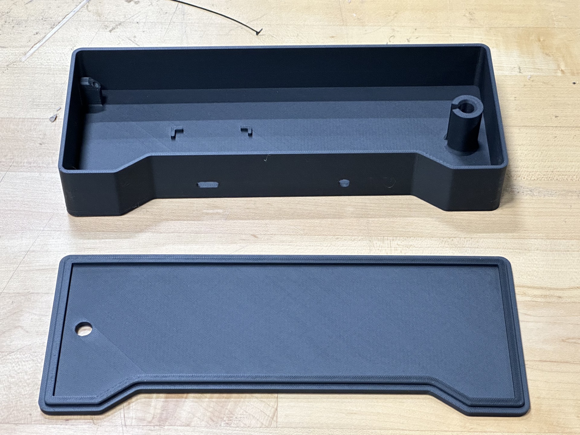
On the left are two holes with supports to hold a copper coil in place. Truthfully, I found a 1/8" copper rod in my lab and figured I could bend it into a good coild for the volume control. The other side is a large metal rod, and in my lab I cannibalized a chemistry beaker holder thing (sorry I'm not a chemist I don't know what they are called). This had threads so I can use that to my advantage and attach the rod by screwing it in to some printed threads (I know that printing threads is a crime but we are really on a time crunch here). For all my struggling with I2S and software, it's times like this that remind me I can do stuff well because I looked at the threads and thought, "oh yeah that looks like 7/16-14 thread," and I don't think that's a normal thing outside of MechE, but I designed a box around it and printed it and let me tell you, the absolute rush when it all assembled perfectly on the first try hit different. The printed box is shown below. Behold.
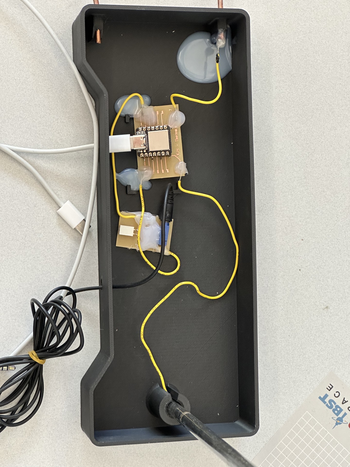
Assembling the Theremin was rather straightforward, the post was screwed into the threaded hole, the copper coil fit snuggly into the holes, and the brackets for the circuit fit the PCB well. I sent the capacitive touch wire to the antenna through the threading and used the threads to hold it in place, this way I could avoid any extra soldering. the copper coil was different. I wanted to crimp the ends but I couldn't find crimps. Ain't that just the way. I quickly learned why you cant solder to a large piece of copper, but after some filing and tenacity on my part I eventually got some solder to hold the wire to the copper coil, and I promptly covered that bad boy in a metric shitton of hot glue. Strain relief, right? That's the justification. I then realized I could hot glue "strain relief" buttons ~everywhere~ and so I committed my second crime of the week doing so. After the glue dried I realized how utterly heinous it looked. Truly awful, and I'm not pround, but that's what the lid of the box is for - nobody has to see that except me (and I guess you now, sorry for cursing you with this knowledge), but hey if it fits it ships. Below are the unholy innards of my Theremin.
On the software side, I heavily adapted the code from Quentins touch piano. The timing and interrupts were essential in tone generation the way I was looking for. He uses a square wave, and while I would rather a sine wave, this is ok for the week's scope. After importing the QTouch readings from the v1 Theremin software (last weeks code), I mapped the readings to volume and pitch parameters using the ever-so-handy "map" function in C. In the setup I added a baseline measurement because I noticed that the output values for the QTouch varied a lot in scale, but the relative range was always around 50 incriments. From this I can gather a baseline in setup and then subtract it in the loop to ensure my mapping range is always 0 to 50. I added some wraps to ensure my values were never negative and that they were properly bounded the way I needed and that was essentially it. I had some timing issues with the delay - it created steps in the sound, but getting rid of the delay made the sound very static-y sounding, so I added an exponentially weighted moving average to smooth out the sound. I chose an alpha value of 0.05 by playing with different values and choising the one I felt had the best balance of smooth + responsive. Adding in more robust filtering along with a sine wave would be nice, but I'm running out of time this week to do that, so I leave it as an exercise for the reader. Another thing is that the capacitive response is not linear, it is exponential in nature, so to get a linear response with the sound we would need to map the curve and then interpolate to it instead of the linear mapping. This would be awesome and absolutely a good next step, but again a nice to have in the future.
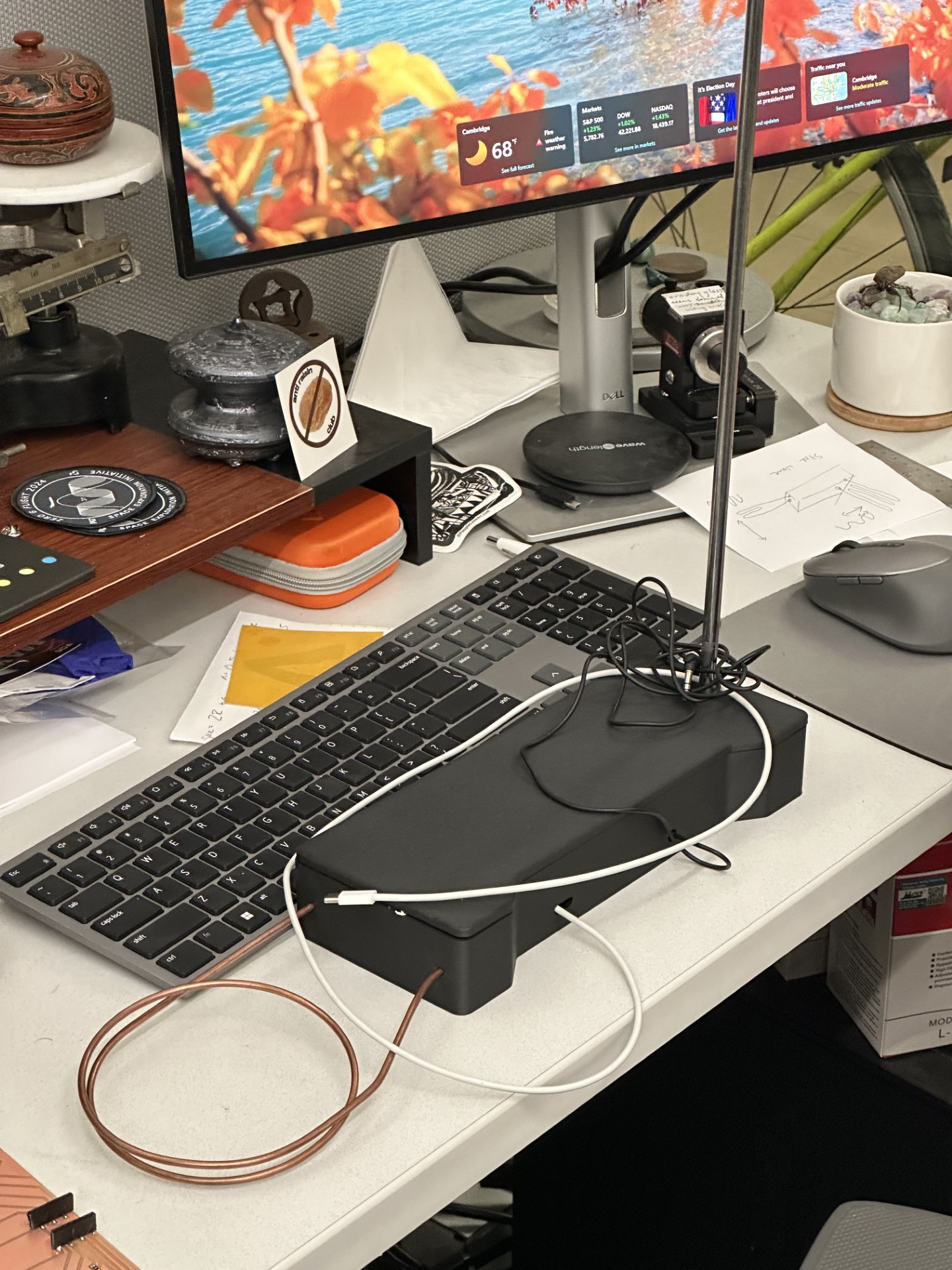
If I end up making another Theremin, I would probably like to just make it analog with a genuine heterodyne oscillator. This would be fun, and it's a tempting final project idea...
So there you have it! A Theremin! It's a little quirky, but that's ok. This week was filled with a wild mix of emotions, but the victory here is divine. 10/10 week. Enjoy some music below (ft. guest artist Neil!), and the files are also around somewhere down there. To next week!
Files for this week
- Download PCB Milling File
- Download PCB PNG
- Download PCB Edge Cuts PNG
- Download STEP Theremin Box
- Download STEP Theremin Box Lid
Code
//
// Theremin Software v2.1
//
// Kyle Horn 11/05/2024
//
// This work has been modified from the original version, detailed below.
// =====================================================================
// hello.touch.D21.ino
//    SAMD21 XIAO FreeTouch hello-world
// Neil Gershenfeld 7/23/24
//
// d21_synth.ino
// Quentin Bolsee
//
// This work may be reproduced, modified, distributed,
// performed, and displayed for any purpose, but must
// acknowledge this project. Copyright is retained and
// must be preserved. The work is provided as is; no
// warranty is provided, and users accept all liability.
//


#include "Adafruit_FreeTouch.h"
#include

#define PIN_BUZZER 2
#define SIG_VOL 400
#define FACTOR_MAX 20000UL

Adafruit_FreeTouch t6 = Adafruit_FreeTouch(0,OVERSAMPLE_64,RESISTOR_100K,FREQ_MODE_NONE); // pin 6 is actually 0
Adafruit_FreeTouch t7 = Adafruit_FreeTouch(1,OVERSAMPLE_64,RESISTOR_100K,FREQ_MODE_NONE); // pin 7 is actually 1

int t6min,t7min;
int32_t baseline6,baseline7;

Ewma adcFilter(0.05);   // Less smoothing - faster to detect changes, but more prone to noise

// SYNTHESIZER
uint32_t count = 0;
uint32_t count_max = 0;
uint32_t freq = 440;
uint32_t freq_samp = 44100;
uint32_t factor = 0;
uint32_t sig_prev = 0;


void tcConfigure(uint16_t sampleRate) {
  GCLK->CLKCTRL.reg = (uint16_t) (GCLK_CLKCTRL_CLKEN | GCLK_CLKCTRL_GEN_GCLK0 | GCLK_CLKCTRL_ID(GCM_TC4_TC5)) ;
  while (GCLK->STATUS.bit.SYNCBUSY);
  tcReset();
  TC5->COUNT16.CTRLA.reg |= TC_CTRLA_MODE_COUNT16;
  TC5->COUNT16.CTRLA.reg |= TC_CTRLA_WAVEGEN_MFRQ;
  TC5->COUNT16.CC[0].reg = (uint16_t) (48000000UL / sampleRate);
  while (tcIsSyncing());

  NVIC_DisableIRQ(TC5_IRQn);
  NVIC_ClearPendingIRQ(TC5_IRQn);
  NVIC_SetPriority(TC5_IRQn, 0);
  NVIC_EnableIRQ(TC5_IRQn);

  // enable interrupt
  TC5->COUNT16.INTENSET.bit.MC0 = 1;
  while (tcIsSyncing());
}

bool tcIsSyncing() {
  return TC5->COUNT16.STATUS.reg & TC_STATUS_SYNCBUSY;
}

void tcStartCounter() {
  TC5->COUNT16.CTRLA.reg |= TC_CTRLA_ENABLE;
  while (tcIsSyncing()); //wait until snyc'd
}

void tcReset() {
  TC5->COUNT16.CTRLA.reg = TC_CTRLA_SWRST;
  while (tcIsSyncing());
  while (TC5->COUNT16.CTRLA.bit.SWRST);
}

void tcDisable() {
  TC5->COUNT16.CTRLA.reg &= ~TC_CTRLA_ENABLE;
  while (tcIsSyncing());
}

void setup() {
  SerialUSB.begin(0);

  while (!Serial);
  t6.begin();
  t7.begin();
  t6min = t7min = 1e6;
  baseline6 = t6.measure();
  baseline7 = t7.measure();

  // BUZZER
  pinMode(PIN_BUZZER, OUTPUT);
  analogWriteResolution(255);
  analogWrite(PIN_BUZZER, 0);
  update_freq(440);

  // SYNTHESIZER
  tcConfigure(freq_samp);
  tcStartCounter();
}

void update_freq(uint16_t val) {
  freq = val;
  count_max = freq_samp / freq;
}

void TC5_Handler (void) {
  // busy DAC, abort this sample
  if (DAC->STATUS.bit.SYNCBUSY == 1) {
    // re-enable interrupt
    TC5->COUNT16.INTFLAG.bit.MC0 = 1;
    return;
  }

  uint32_t sig, samp;

  sig = 0;
  if (count >= count_max / 2) {
    // square wave of wanted frequency
    sig += SIG_VOL;
  }
  count++;
  if (count >= count_max) {
    count = 0;
  }


  samp = sig * factor / FACTOR_MAX;
  DAC->DATA.reg = samp & 0x3FF; // 10 bit DAC

  // re-enable interrupt
  TC5->COUNT16.INTFLAG.bit.MC0 = 1;
}


void loop() {

  int32_t result6,result7;
  //
  // plotting scale limits
  //
  Serial.print(0);
  Serial.print(",");
  Serial.print(300);
  Serial.print(",");
  //
  // read touch
  //
  result6 = t6.measure()-baseline6;
  if (result6 < t6min) t6min = result6;
  Serial.print(result6-t6min);
  Serial.print(",");
  result7 = t7.measure()-baseline7;
  if (result7 < t7min) t7min = result7;
  Serial.print(result7-t7min);
  Serial.println("");

  //delay(10);


  if (result7 <= 50){
    factor = map(result7, 0, 50, FACTOR_MAX, 0);
  }
  else{
    factor = 0;
  }

  float filtered1 = adcFilter.filter(result6);

  int32_t val;
  val = min(max(map(filtered1, 0, 50, 98, 1046.5),98),1046.5);

  update_freq(val);

}

} 