Electronics Production
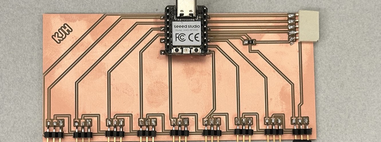
This week we were tasked with producing the boards we designed last week in Electronics Design. The scope of "production" here includes the milling, post processing, component selection and solering, and continuity checking of the traces. This is a very involved week, and it will be important moving forward in the class. Let's get moving.
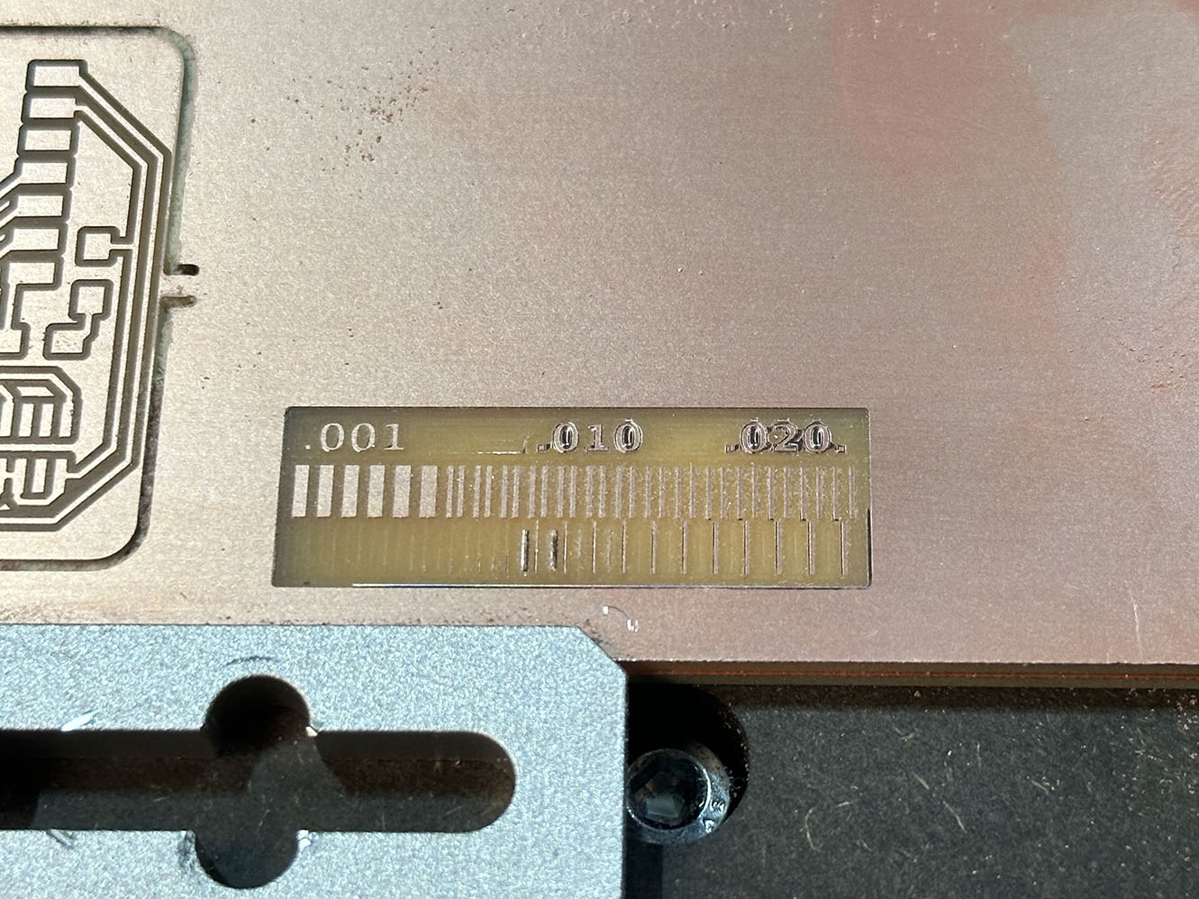
As per usual, we start with the group assignment. This week we needed to both "place" an order for a custom PCB to a boardhouse as well as learn about our milling machine - for the CBA section this is the Carvera. The Carvera is a fully automated CNC mill - complete with tool changes, auto-leveling, etc. Very fancy. Specifically we wanted to look at the design capabilities of the machine with the 16mil bit it typically works with. Below is a milling pattern we subjected the machine to, and it did rather well.
From this, we are able to begin the production of the board designed last week for actuating the sax keys. A few design tweeks were made to the board traces so they could fit on a single layer. This was achieved using clever routing and sort of cheat code by using a 0-ohm resistor as a jump. The updated board was exported as a .gbr file and then uploaded into gerber2img (which is a blessedeth tool so kudos to the class staff for making it). The process is simple, just drag and drop, shown below.
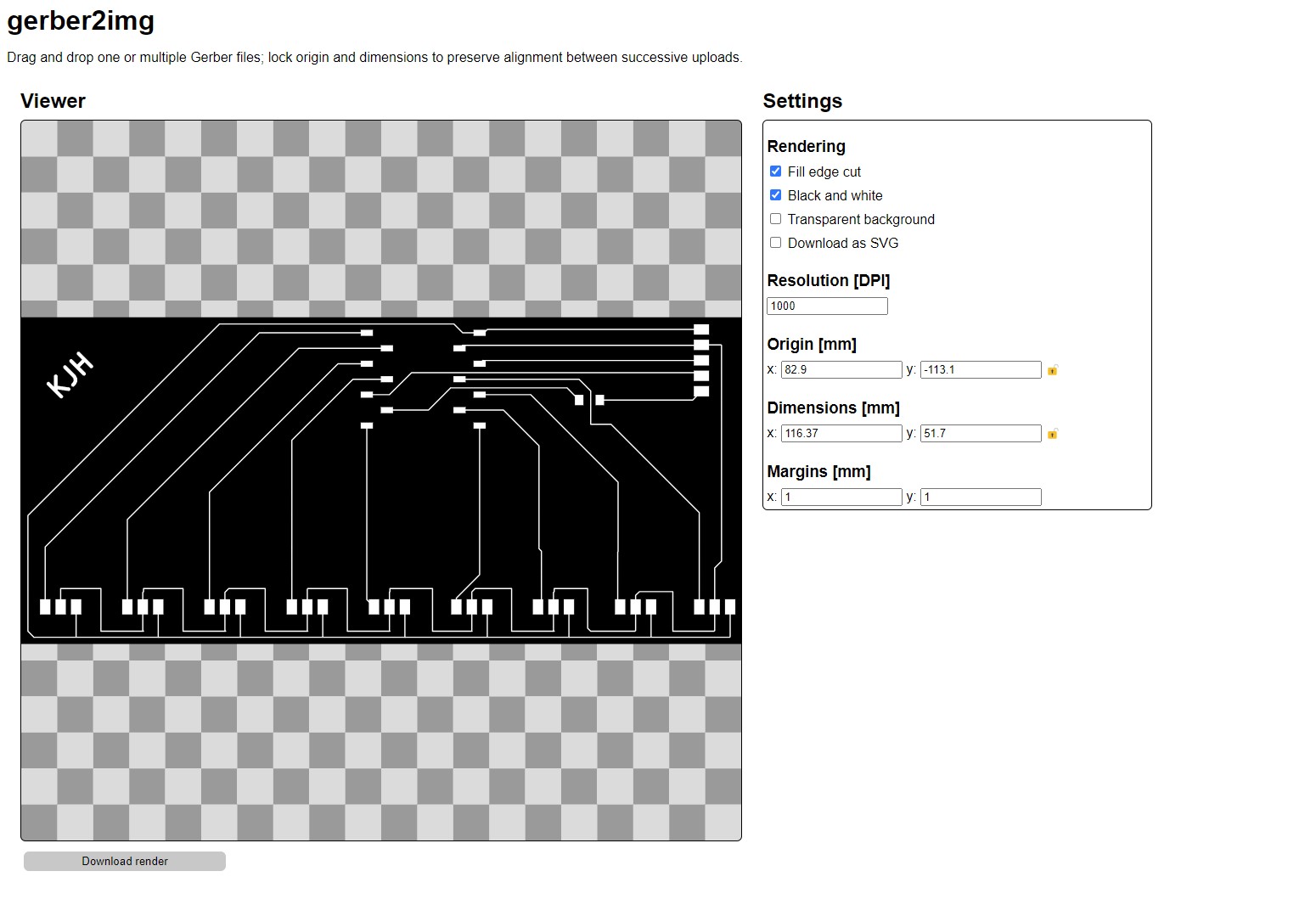
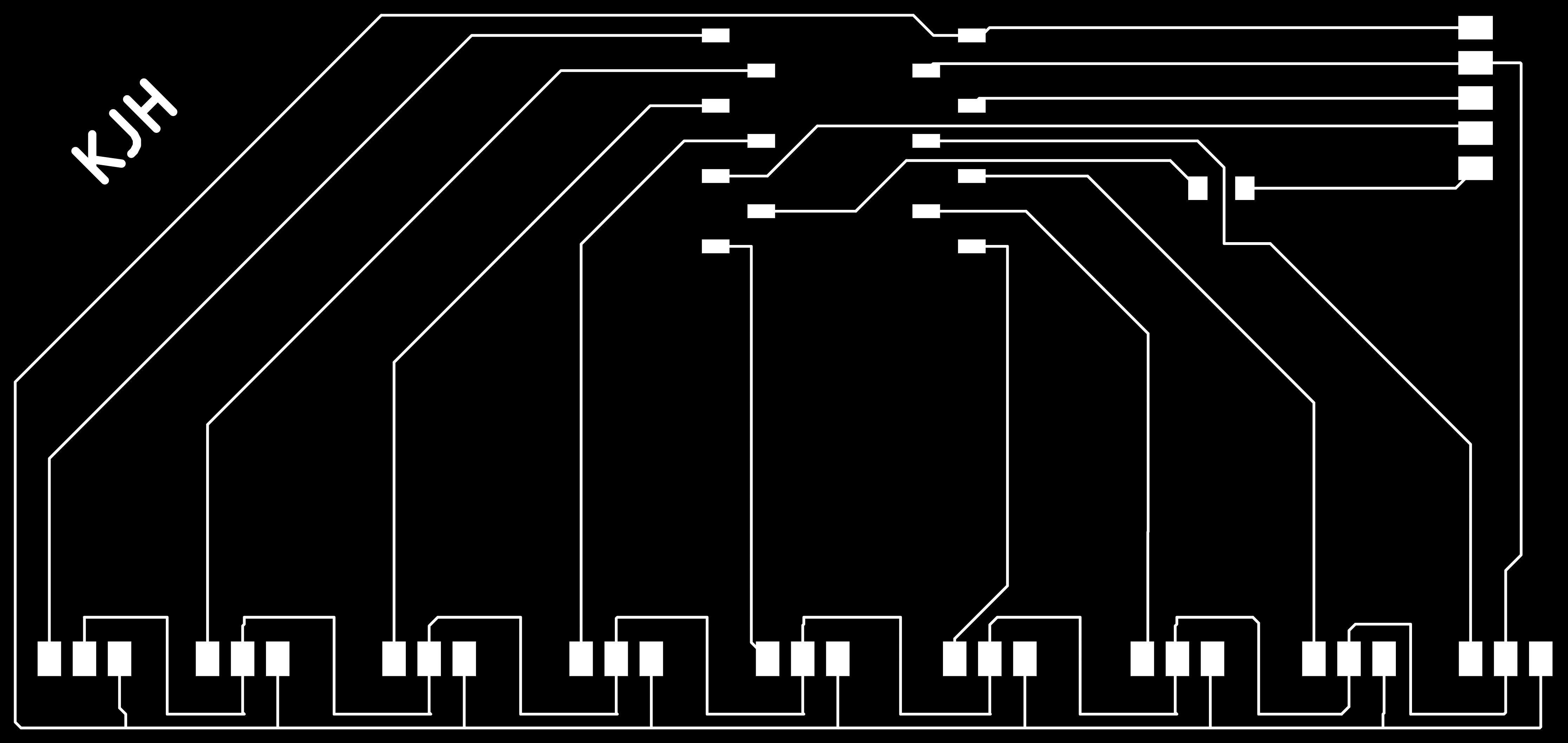
The output is a png image that is incredibly high quality for the mill mods to use. The pngs are shown below. Note that the second png is just a blank rectangle. This is for the edge cuts the mill will make. They need to be thicker and distinct from the rest of the milling, so they get their own png.

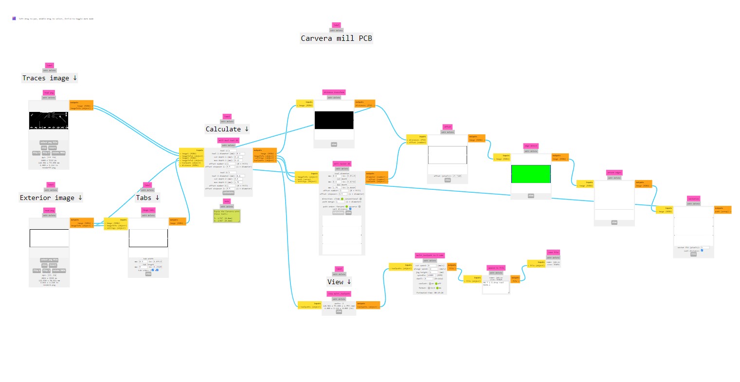
Now that we have the pngs for the gerber files of the board, it's time to throw them into *mods*. This horrifying looking jumble of lines is not a conspiracy theory pinboard, but rather a dataflow diagram that processes the png files into gcode for the Carvera to use. It was developed by CBA and this specific dataflow mod was developed by the TAs (once again, the TAs are putting in the real legwork here). The mods dataflow also shows the user the tool path for the Carvera. Both the tool path and the dataflow diagram are shown below.
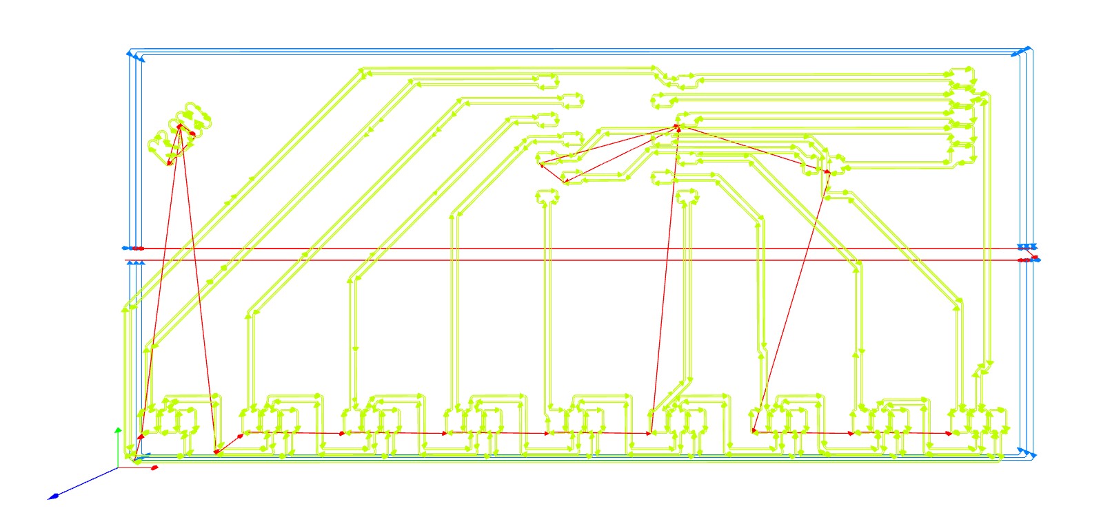
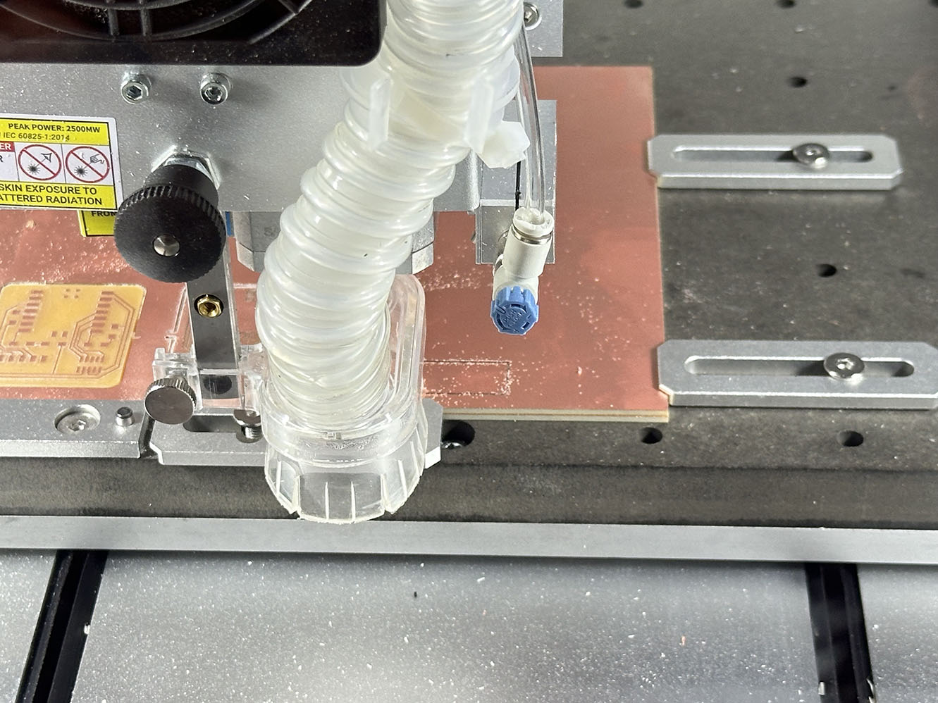
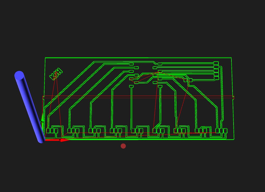 Since mods took care of the gcode for the mill, its time to actually start milling the board. The Carvera renders the tool path as well before it starts the job, so that's nice. Here is the Carvera version of the path off to the right.
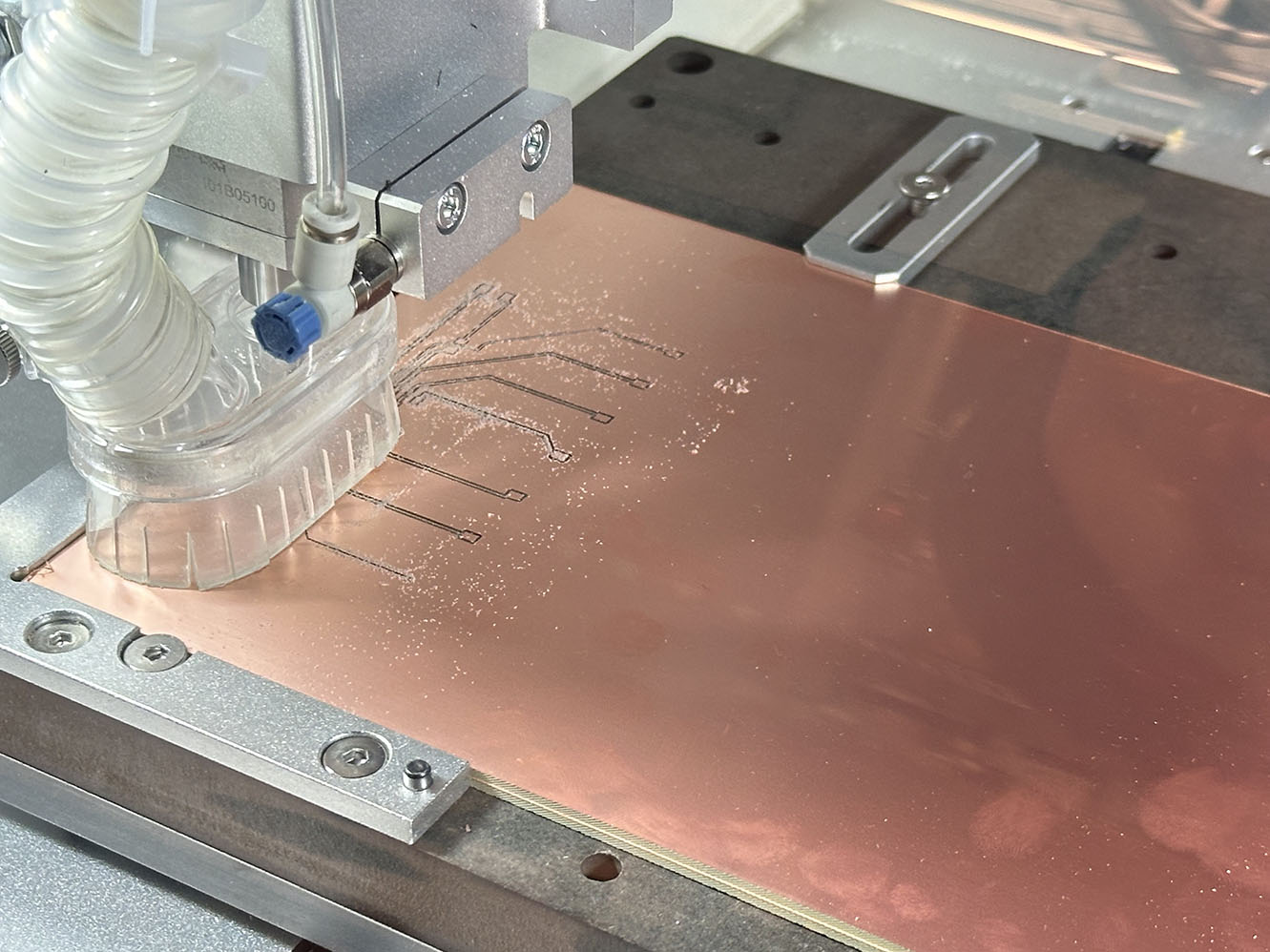
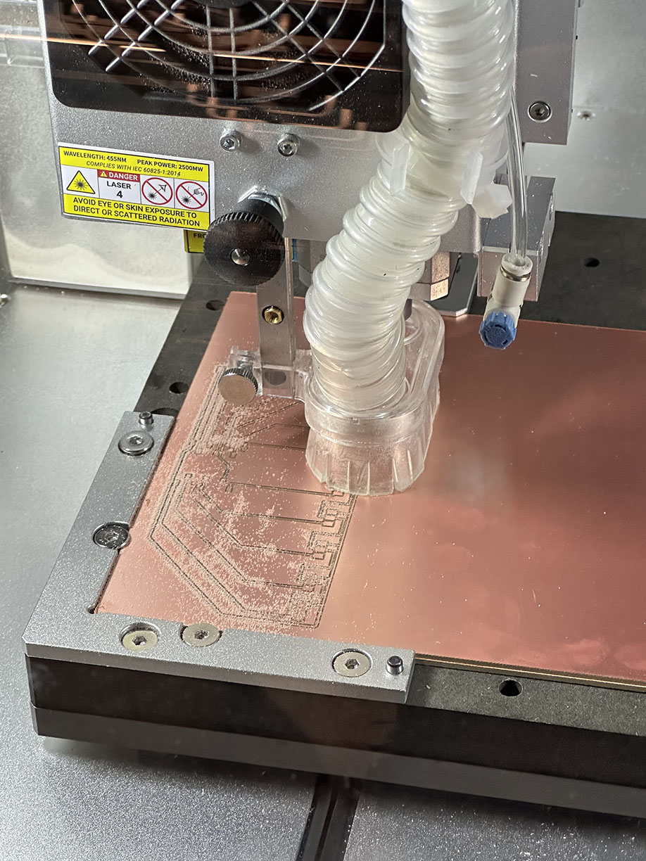
As we start milling, the Carvera selects the tool as specified in mods - here it is the 16mil bit. Below you can see the Carvera work its magic and chip away at the design rather quickly. The entire job took only 20ish minutes from start to finish. Compared to the several hours during 3D printing week this is a big improvement for morale. I am unsure if it is because of careful planning or sheer dumb luck, but this board came out perfectly on the first try. I'll be.
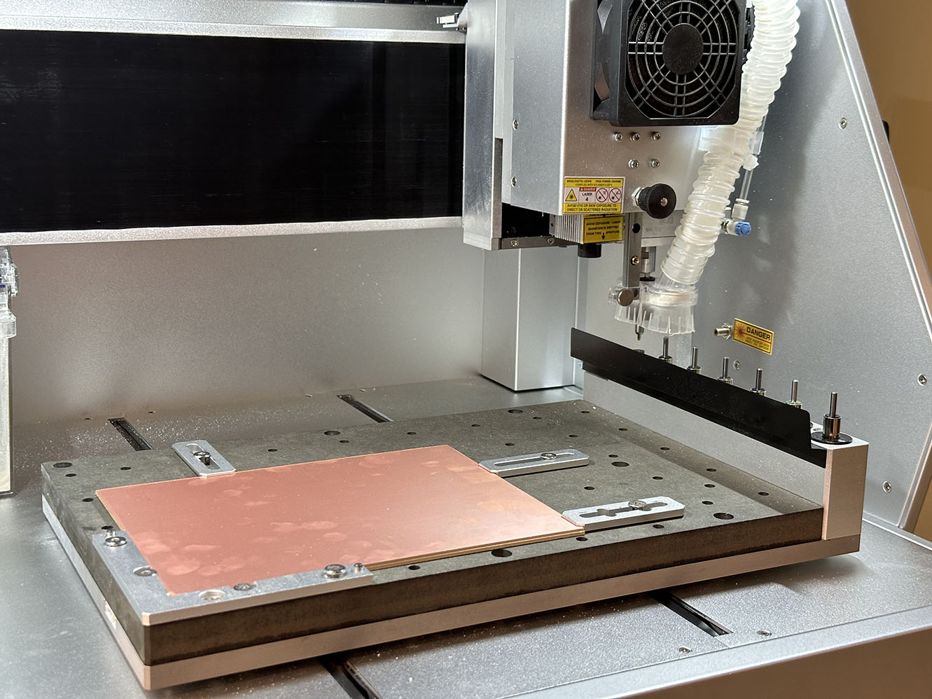
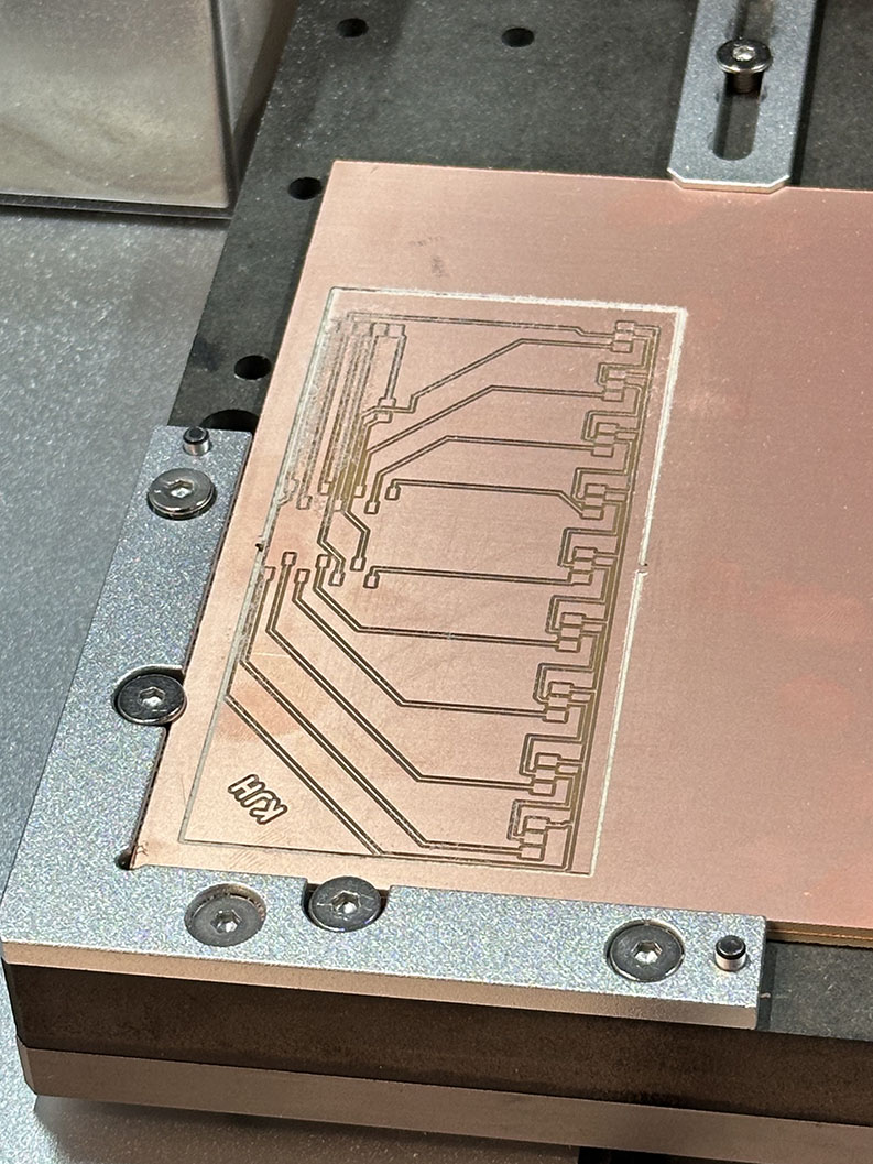
Great! That was the easy part. Time to now process the board and solder everything together. To start off the processing, we need to check that the traces are ok and not broken or shorted anywhere on the board. This is easily accomplished a couple of ways: the multimeter or visually. As a casual enjoyer of looking at things, I opted to look at the board under a microscope. A few traces are shown below.
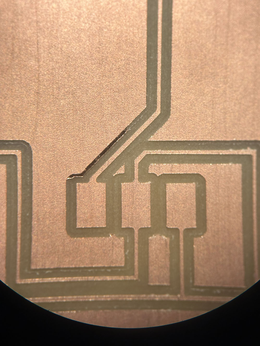
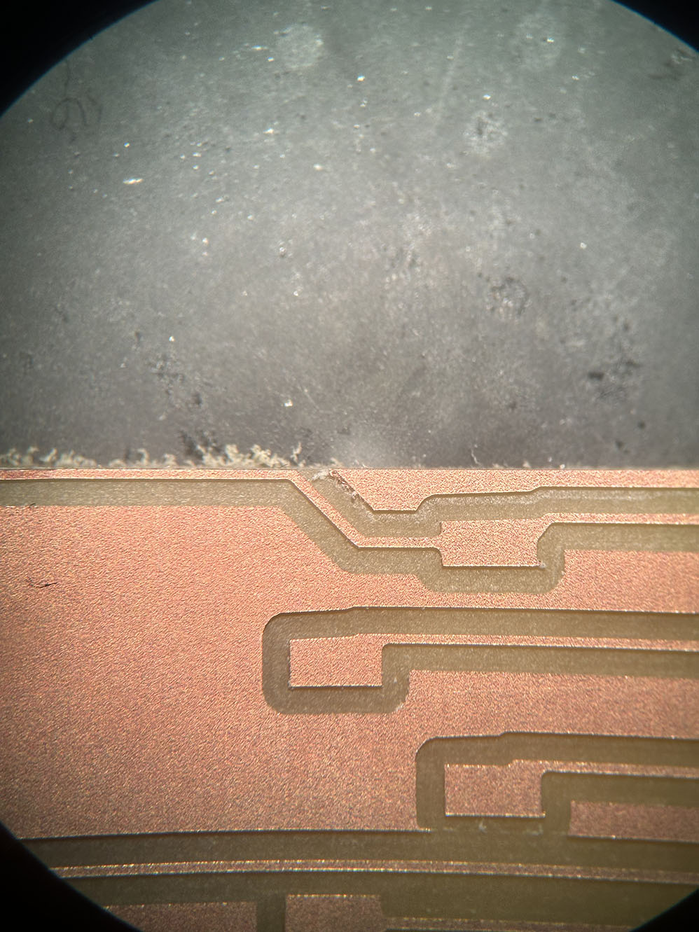
Everything looks ok here for the most part. Something interesting and a little concerning is that the trace in the figure above to the right is at the edge of the board where the cut was made. In the schematic I uploaded to mods this was ofset by a few mm from the edge. I am unsure where the issue arose but something fishy is going on. The tace maintains continuity so that is good enough for this weeks assignment, but will be something to keep in mind for future milling.
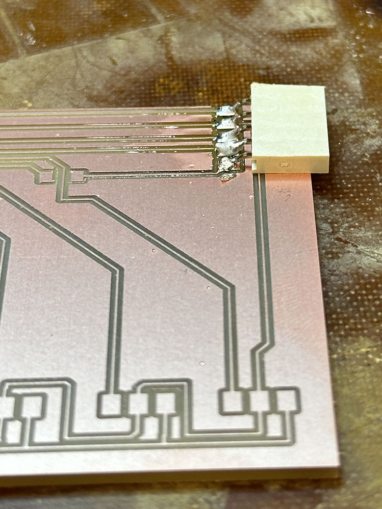 Now it's time to start the soldering! As I have never formally soldered anything in my professional life, this is going to take some trial and error. Thankfully, right as I was beginning to strugle, Quintin showed up and gave me a quick Soldering 101 which was an absolute godsend. Thank you TA Quintin for saving me here. He started me off with the connector on the right side of the board and I took it from there. His tutorial was helpful in showing me a little bit of the technique I should be aiming for as well as how to clean up the joints with additional flux, and how to tin a pad to help anchor a part before soldering the rest of it.
Moving on, it is time to solder for myself now. I decided to next solder the feet for the Xiao seeed RP2040. Because this board is a development board, I did not 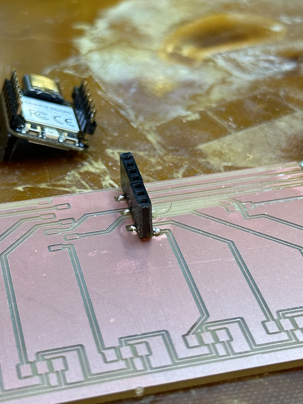 want to solder the Xiao directly to the board, but rather pin it using some header pins. The pads for those are very small, but the soldering of them was surprisingly easy. See below for a once-in-a-lifetime first solder joint.
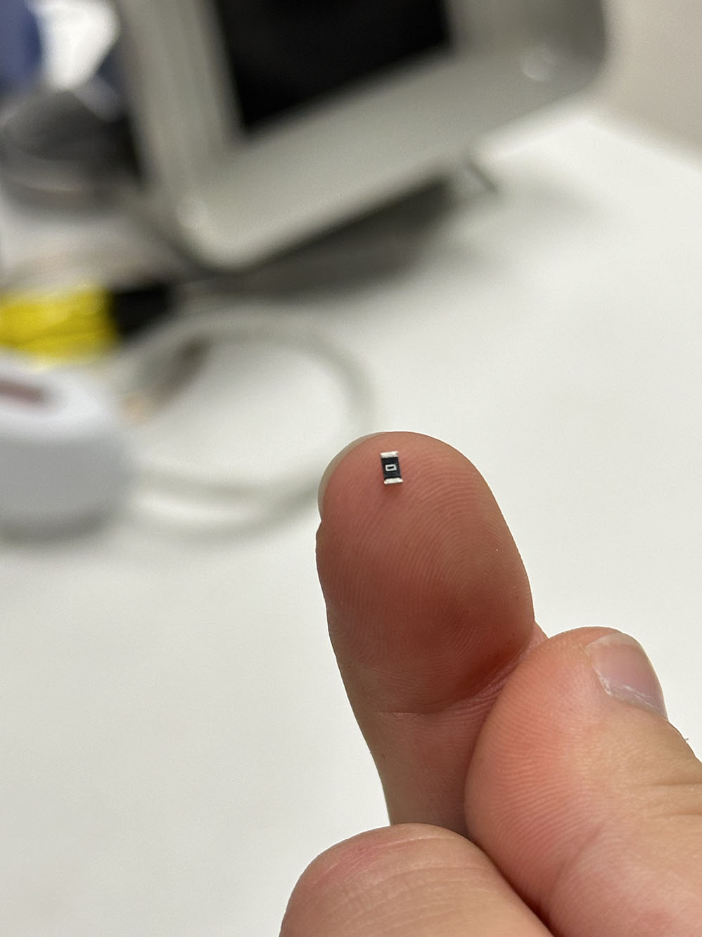
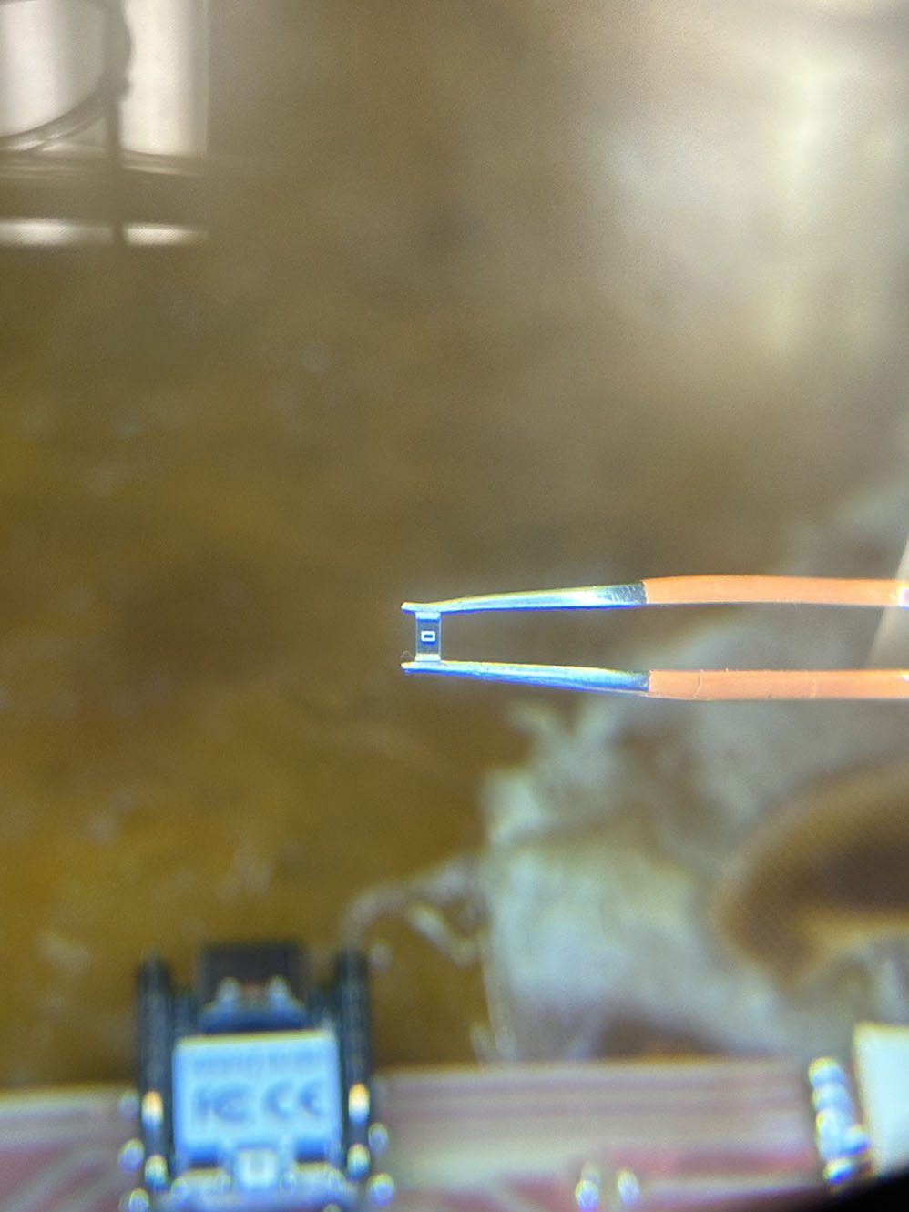
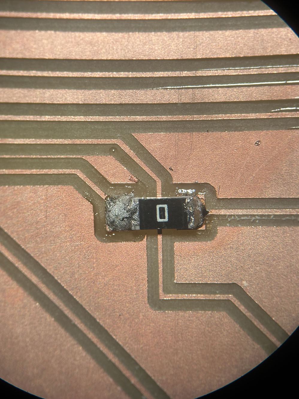
I soldered the rest of the feet to the pads and ensured good adhesion before continuing to the next components. In this case, I have graduated to expert mode of soldering, since the next task is to solder the 0-ohm resistor. "But Kyle, how hard can that really be?" The answer: f**king awful. When I was a kid, there was a parking garage that my mom would drive in at one of my doctors offices, and this particular garage had many tight turns and blind corners. I learned a lot of vocabulary in that parking structure, and much of it is returning in this moment.
I did eventually get it, and the results are shown below. Admittedly, a few of the images I included were placed to gain some sympathy for the size of this stupid little part. It ain't pretty, but it'll get the job done.
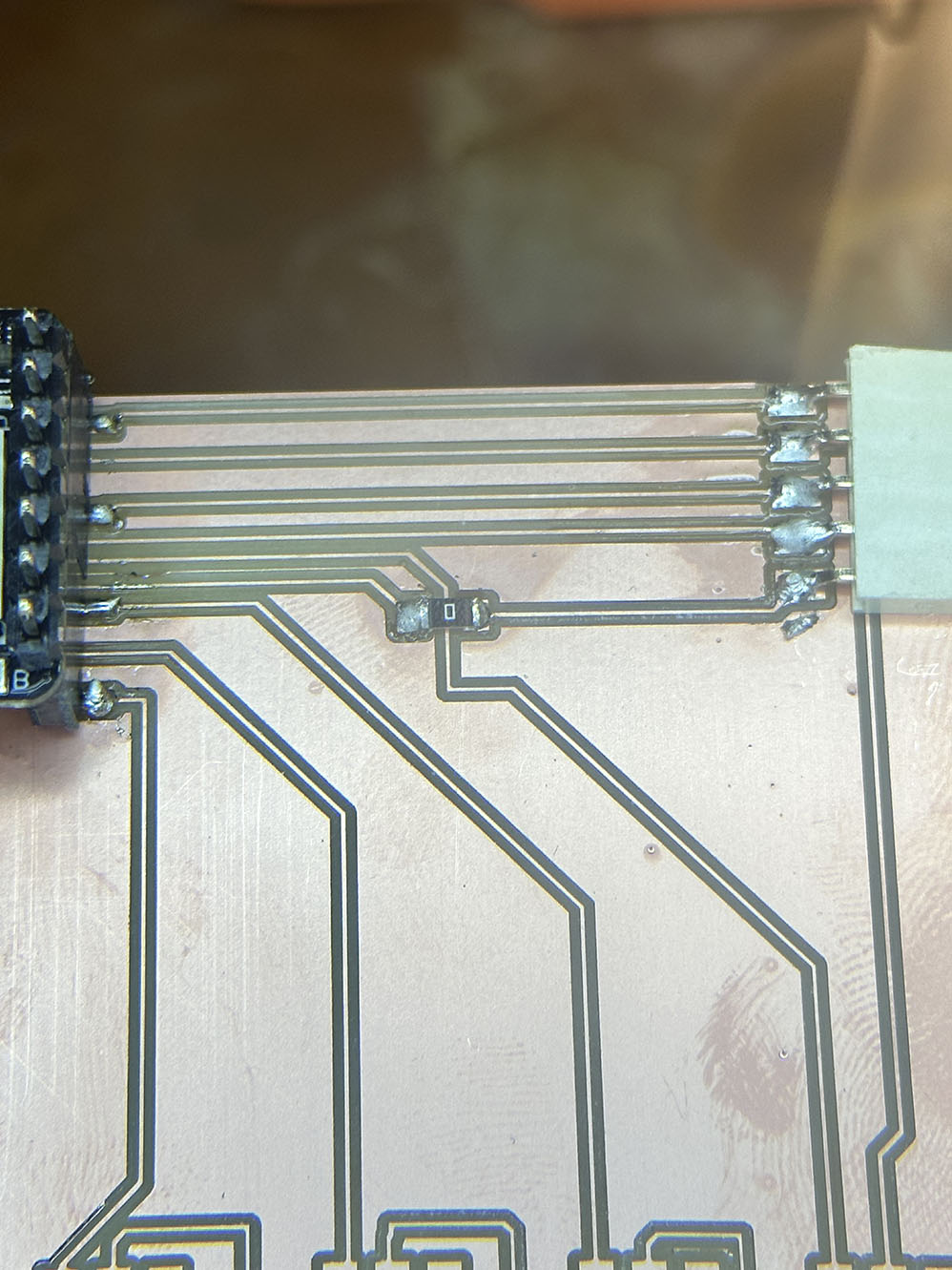
Now that I have my honorary degree in soldering, time to knock out the servo connections. I started by pre tinning the power connection pad for each of the header pins, shown below. After that, the first set of pins was attached. It was here that I learned the benefits of the vice clamp for helping me on my soldering voyage. It's almost like all of the tools on this workbench are here for a reason. The rest of the soldering for the header pins took some time, but it was rather easy by comparison to the resistor above.
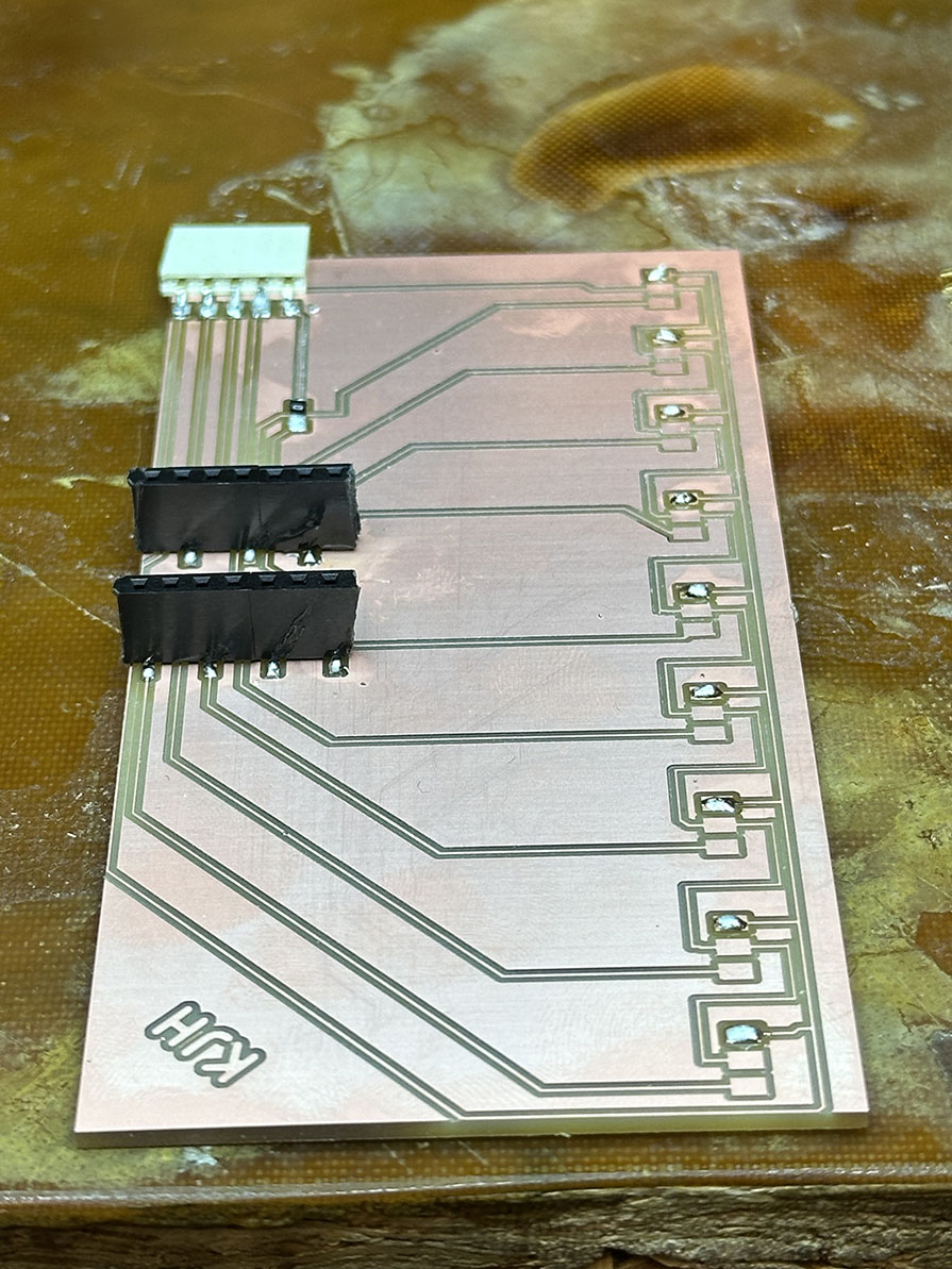
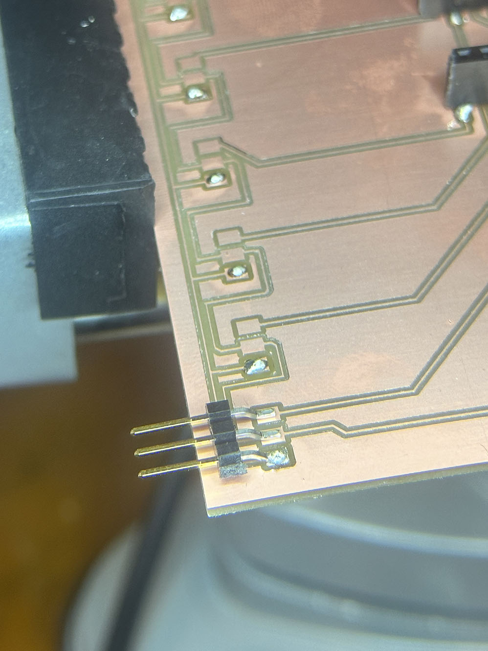
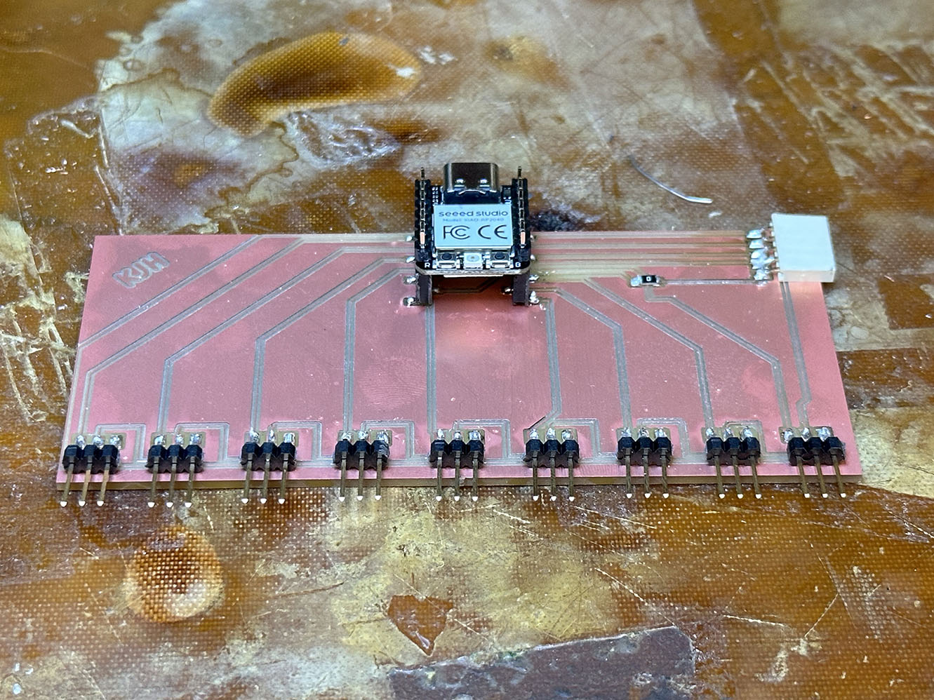
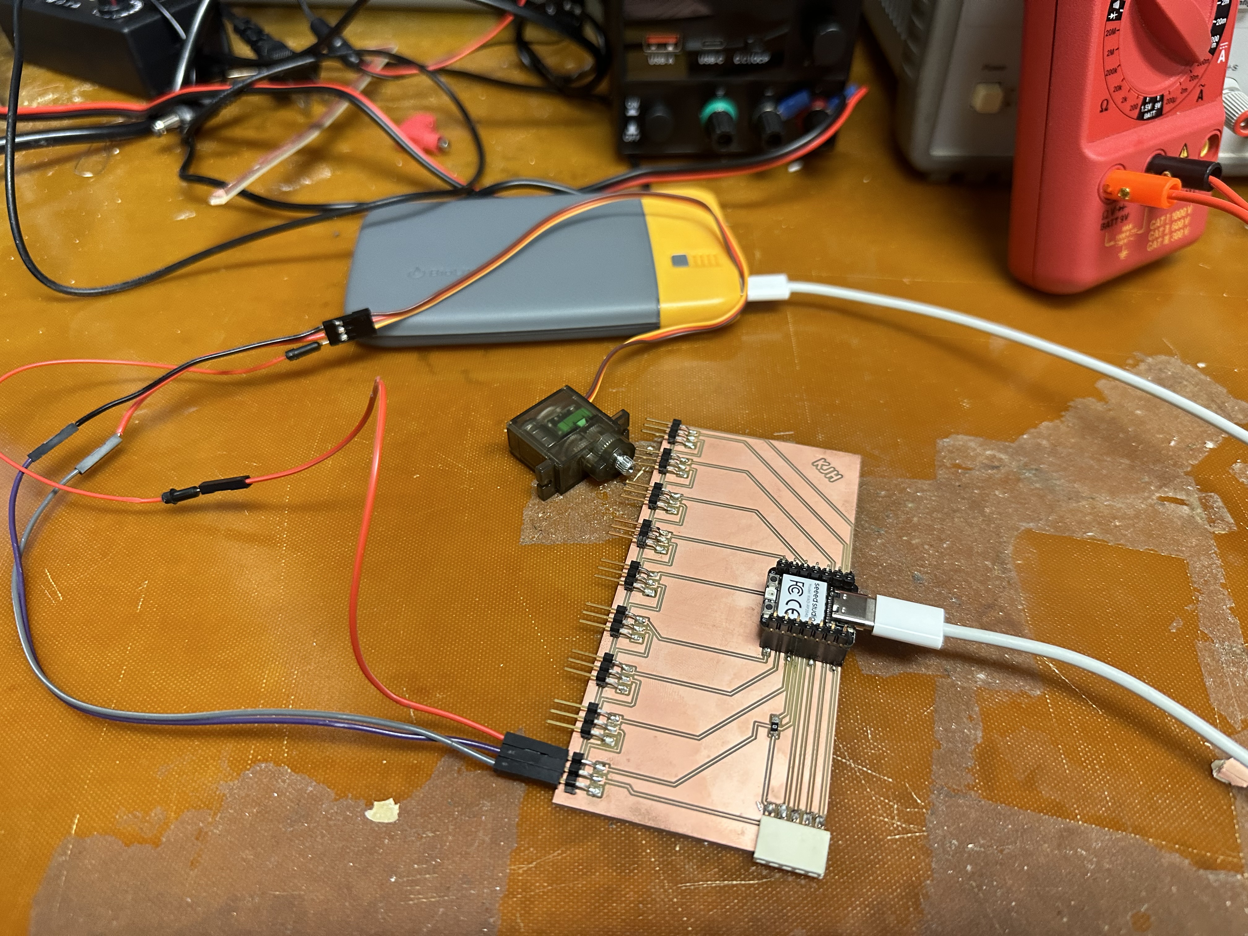
And that concludes the week! There is a fine art to making PCBs, and the TAs are true artists. Many valuable lessons learned, most notably, however, is that the soldering iron is hot and the suff it touches also becomes hot. Seems silly but the principles of heat transfer really sneak up on ya when you aren't thinking about it. Beyond that, see below for the final picutre (I attached a servo to one of the pins for novelty). To next week!
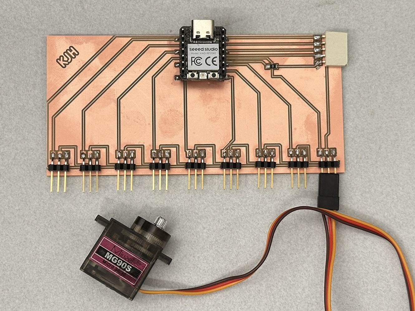
And after quite a bit of debugging, here is the setup turning a simple servo sweep!
