Input Devices
This week we are covering input devices, so the goal for the assignment is to read data from a sensor. This is very open ended and there are a lot of sensors to choose from. One bit of guidance that Neil gave in lecture is his affinity for step response and capacitance. I share his opinion here - this is absolutely some of the coolest demos I've seen. Here's a video to see what I mean, but essentially it's using the properties of dielectric capacitive measurements to show distance or proximity to a conductor. My immidiate thought for this was to make a Theremin, so that's what we are going to do here. To scope it right for this week, I won't be making a Theremin entirely, since output devices is next week and that's when I will hook up the speaker, but I can get pretty far this week with reading the capacitive measurements. Let's dive in.
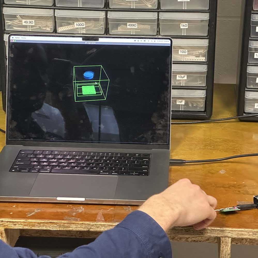
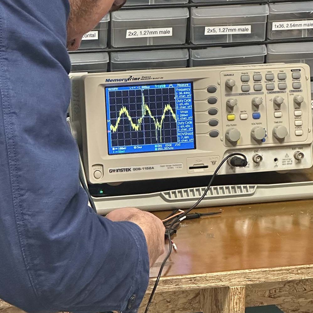
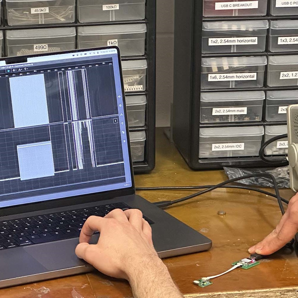
Starting things off, we begin with the group assignment. The task this week is to probe an input devices analog signals and digital signals. To do that we are looking at a magnetic sensor using an oscilloscope. The sensor outputs vector data that has been formatted to show it's relative position in space in post, shown below in the first panel. The oscilloscope hook up is shown next to it where we can see the analog signals coming off the sensor, and finally the digital readout is shown using the Saleae like before.
Moving on to the individual work, to read the capacitive inputs to the sensor, I will make use of the example Neil posted to the course website that outlines a simple "hello world" self-capacitive touch program. This program runs on the XIAO SAMD21 since the SAMD11 chips have native capacitive touch functionality built in to certain pins. These pins are compatible with QTouch, a native touch signal processing algorithm. The toolbox takes care of the processing of the signals for the most part, making this a very easy way to get started with step response.
The pinout diagram for the XIAO SAMD21 is shown below. The QT (yellow highlight) shows which pins support the native QTouch toolbox. For this build, I will be using two of the QT eneabled pins, A6 and A7.
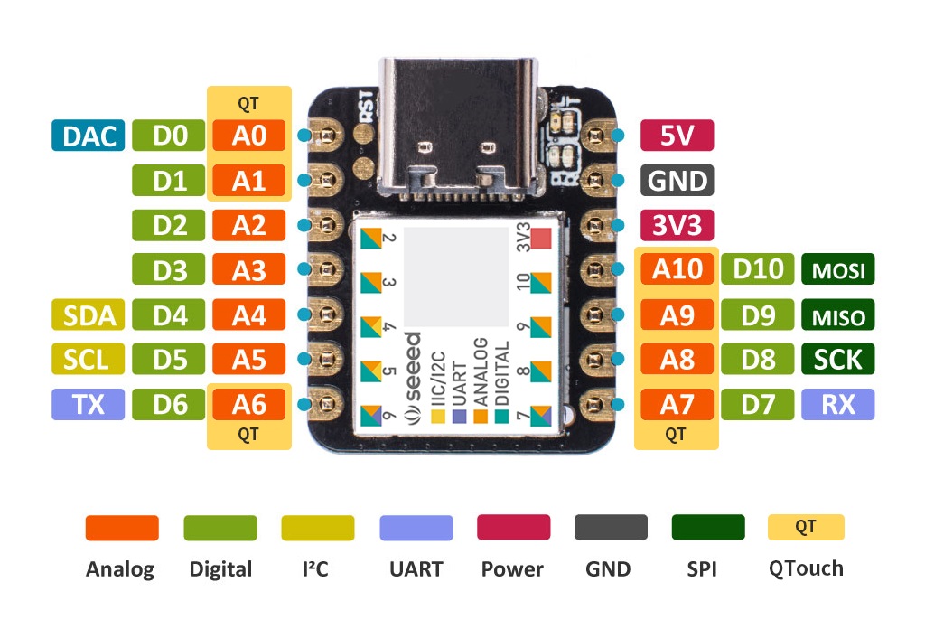
From the pinout diagram, I can make a very simple breakout style board for the XIAO using the process from electronics production. Below is the PNG file made from the .gbr output from KiCad and the corresponding milled board done on the magical Carvera.
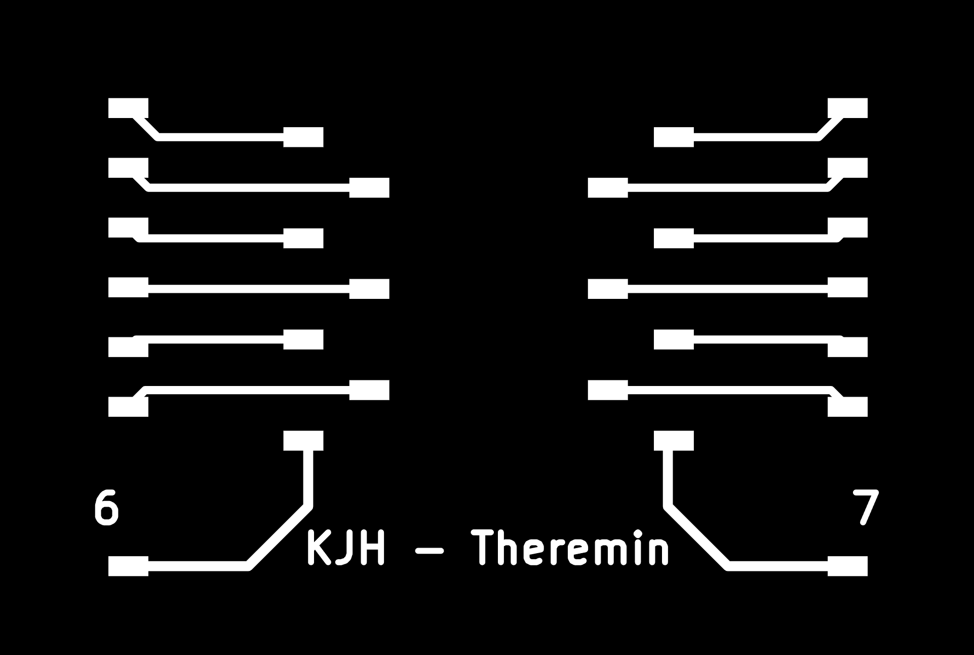
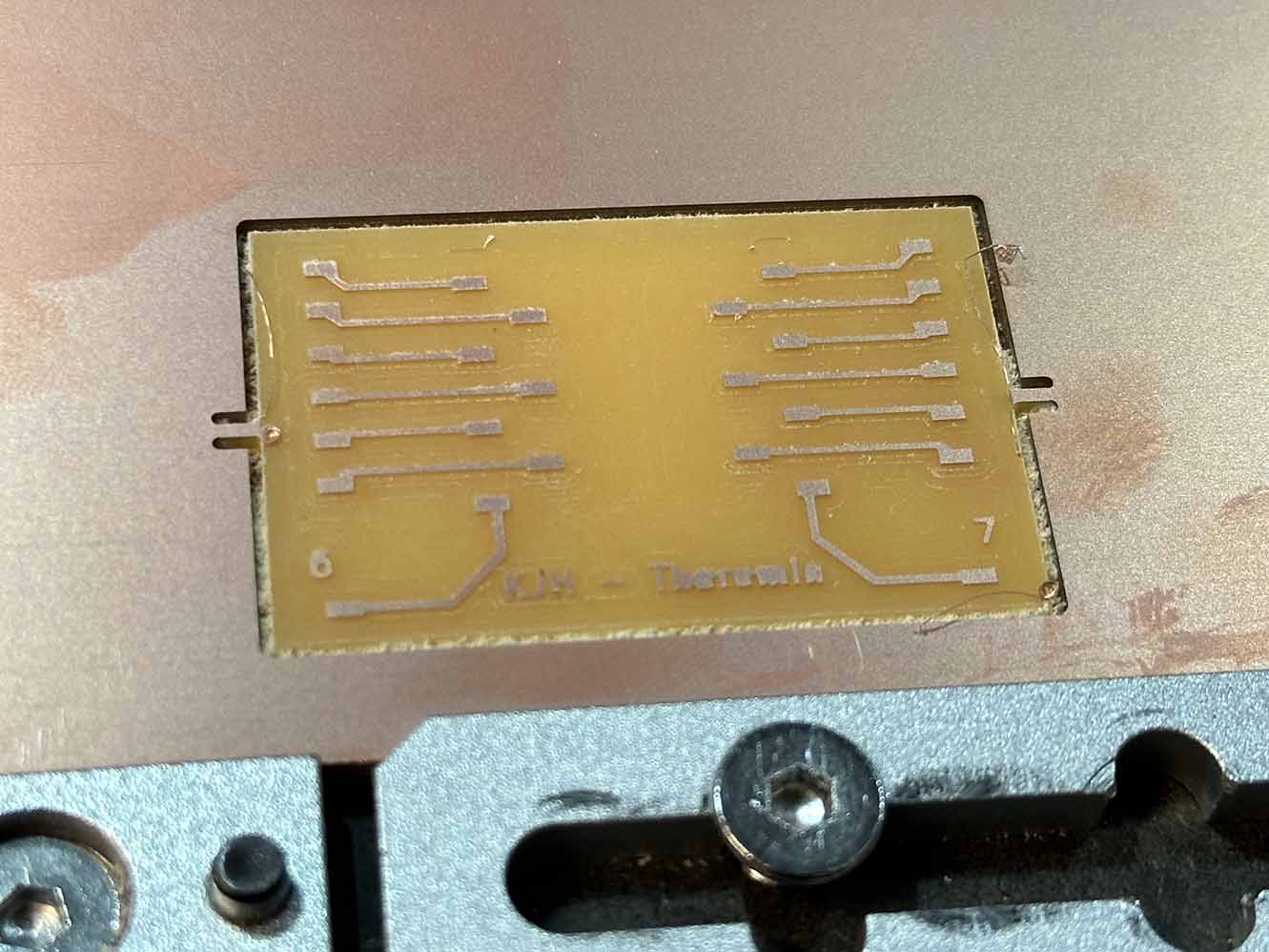
The soldering for the board is incredibly simple - just attach as much conductive material as possible to boost the sensitivity of the step response being measured. The soldered board is shown below. I added some jumper wire to small copper plates for testing the board this week, but this will be removed for next week when I complete the Theremin build.
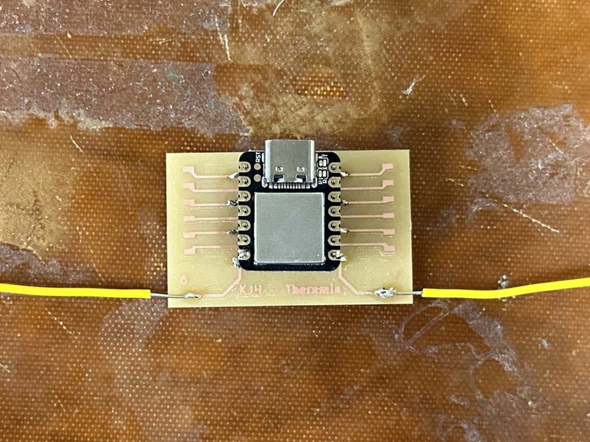
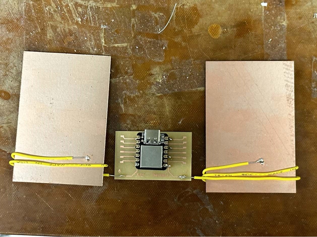
Now that this simple little board is built, let's test the step response. The code used for measuring and plotting the step response is adapted from Neil's "hello world touch" example on the class website. The majority of the headache here was figuring out the XIAO pin mapping to the SAMD21 pins for the variable inputs, but after some trial and error (and help from Quentin - god bless) we have it working (and measuring!) - huzzah!
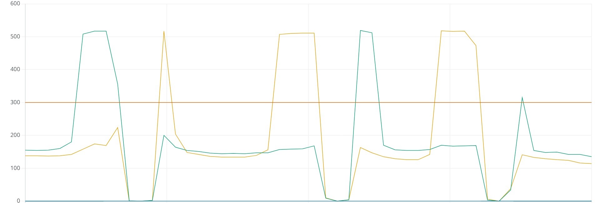
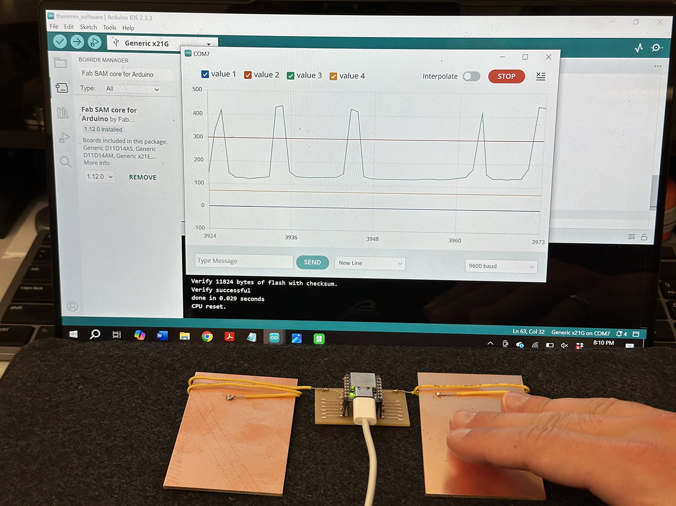
Below you can see the left and right step responses for the board and the corresponding serial plot from the Arduino IDE. Notice how in the left figure for both left and right response the change in dielectric capacitance is registered, then in the right figure there is a large spike when my hand actually touches the plate. This indicates to me that for the full Theremin build I will need to bound the values such that an accidental touch from the player doesn't create some unholy noise-o-mathematics.
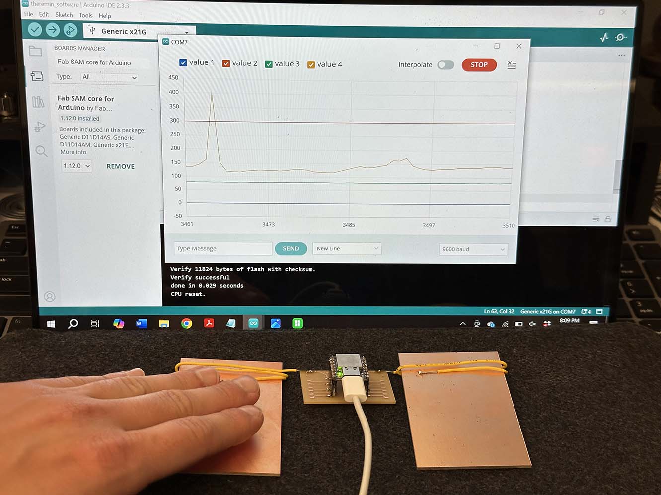
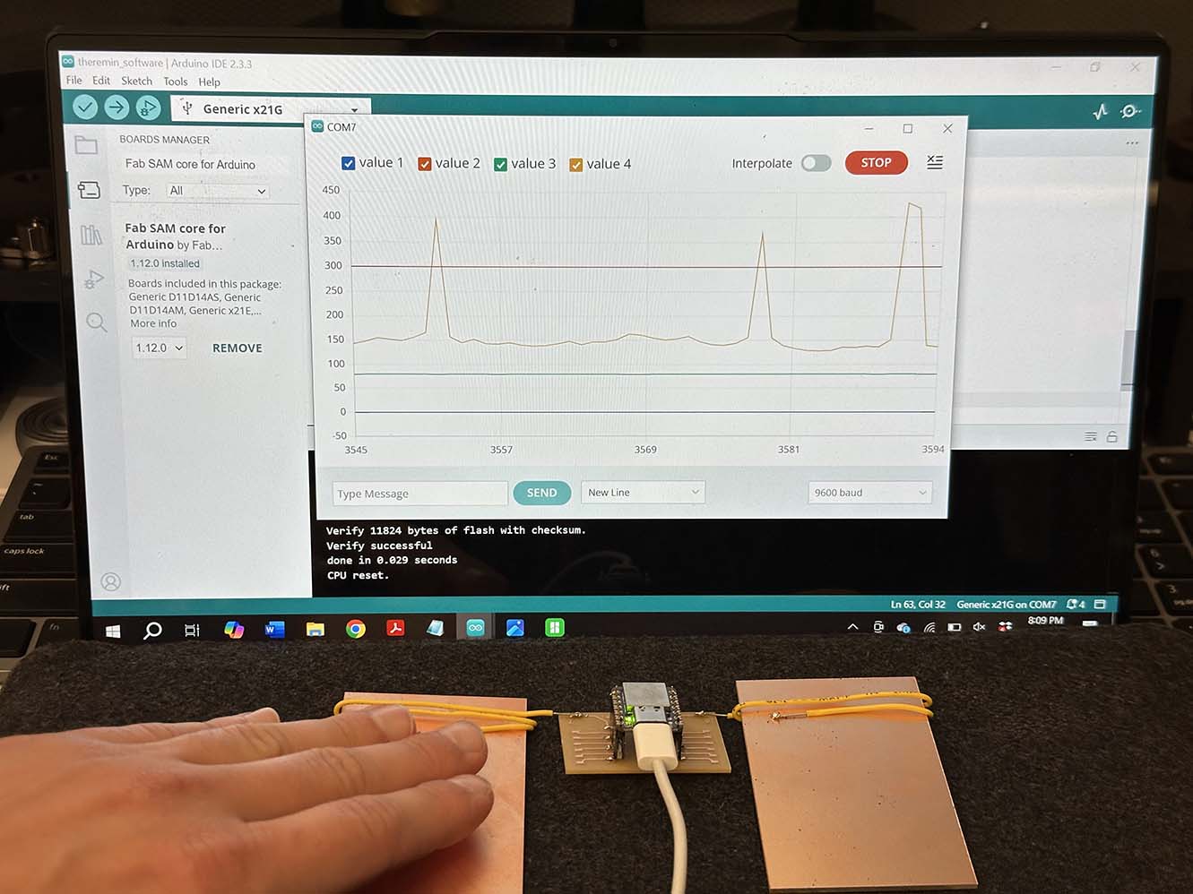
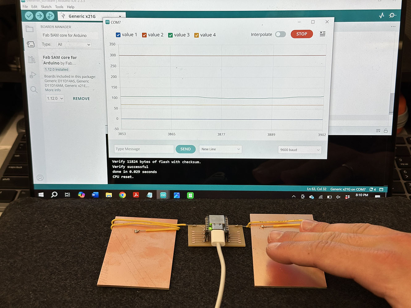
This is super cool. Even with a simple demo this type of measurement has so many applications. To me, this is likely one of the most significant takeaways from the class. Simple, cool, unlimited potential - 10/10 week. Next week in output devices we will correlate this signal to sound and a speaker and make a real Theremin!
As always, here are the files for this week.
Code
//
// Theremin Software v1.2
//
// Kyle Horn 10/25/2024
//
// This work has been modified from the original version, detailed below.
// =====================================================================
// hello.touch.D21.ino
//    SAMD21 XIAO FreeTouch hello-world
//
// Neil Gershenfeld 7/23/24
//
// This work may be reproduced, modified, distributed,
// performed, and displayed for any purpose, but must
// acknowledge this project. Copyright is retained and
// must be preserved. The work is provided as is; no
// warranty is provided, and users accept all liability.
//

#include "Adafruit_FreeTouch.h"

Adafruit_FreeTouch t6 = Adafruit_FreeTouch(0,OVERSAMPLE_64,RESISTOR_100K,FREQ_MODE_NONE); // pin 6 is actually 0
Adafruit_FreeTouch t7 = Adafruit_FreeTouch(1,OVERSAMPLE_64,RESISTOR_100K,FREQ_MODE_NONE); // pin 7 is actually 1

int t6min,t7min;


void setup() {
  Serial.begin(115200);
  while (!Serial);
  t6.begin();
  t7.begin();
  t6min = t7min = 1e6;
  }

void loop() {
  int result;
  //
  // plotting scale limits
  //
  Serial.print(0);
  Serial.print(",");
  Serial.print(300);
  Serial.print(",");
  //
  // read touch
  //
  result = t6.measure();
  if (result < t6min) t6min = result;
  Serial.print(result-t6min);
  Serial.print(",");
  result = t7.measure();
  if (result < t7min) t7min = result;
  Serial.print(result-t7min);
  Serial.println("");
  //
  // pause
  //
  delay(50);
}